Transcription
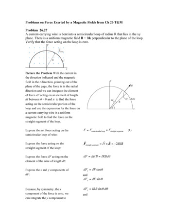
Problems on Force Exerted by a Magnetic Fields from Ch 26 T&MProblem 26.27A current-carrying wire is bent into a semicircular loop of radius R that lies in the xyplane. There is a uniform magnetic field B Bk perpendicular to the plane of the loop.Verify that the force acting on the loop is zero.Picture the Problem With the current inthe direction indicated and the magneticfield in the z direction, pointing out of theplane of the page, the force is in the radialdirection and we can integrate the elementof force dF acting on an element of lengthdℓ between θ 0 and π to find the forceacting on the semicircular portion of theloop and use the expression for the force ona current-carrying wire in a uniformmagnetic field to find the force on thestraight segment of the loop.Express the net force acting on thesemicircular loop of wire:Express the force acting on thestraight segment of the loop:F Fsemicircular loop Fstraight segmentrr rFstraight segment I l " B !2 RIBExpress the force dF acting on theelement of the wire of length dℓ:dF IdlB IRBd!Express the x and y components ofdF:dFx dF cos !anddFy dF sin !Because, by symmetry, the xcomponent of the force is zero, wecan integrate the y component todFy IRB sin ! d!and(1)
find the force on the wire:"Fy RIB ! sin # d# 2 RIB0Substitute in equation (1) to obtain:F 2 RIB ! 2 RIB 026.57 Torque on a loop with currentA rigid circular loop of radius R and mass m carries a current I and lies in the xy plane ona rough, flat table. There is a horizontal magnetic field of magnitude B. What is theminimum value of B so that one edge of the loop will lift off the table?Picture the Problem The loop will start to lift off the table when the magnetic torqueequals the gravitational torque.Express the magnetic torque actingon the loop:" mag µB I!R 2 BExpress the gravitational torqueacting on the loop:! grav mgRBecause the loop is in equilibriumunder the influence of the twotorques:I!R 2 B mgRSolve for B to obtain:B mgI!R
Problem 26.61 27.101 Magnetic moment of a loop and Magnetic field calculationA wire loop consists of two semicircles connected by straight segements. The inner andouter radii are R1 0.3 and R2 0.5 m, respectively. A current I of 1.5 A flows in thisloop with the current in the outer semicircle in the clockwise direction.A) What is the magnetic moment of the current loop?B) Find the magnetic field in P, which is at the common center of the 2 semicircular arcs.Picture the Problem We can use the definition of the magnetic moment to find themagnetic moment of the given current loop and a right-hand rule to find its direction.Using its definition, express themagnetic moment of the currentloop:µ IAExpress the area bounded by theloop:A 12µ "I 22()Router ! Rinner2µ # (1.5 A )(0.5 m )2 " (0.3 m )22Substitute to obtain:Substitute numerical values andevaluate µ:("R2outer)2! "Rinner " 22()Router ! Rinner2[] 0.377 A ! m 2Apply the right-hand rule for determining the direction of the unit normal vector (therdirection of µ) to conclude that ì points into the page.Problem 27.101 Picture the Problem Let out of the page be the positive x direction. Because point P ison the line connecting the straight segments of the conductor, these segments do notcontribute to the magnetic field at P. Hence, the resultant magnetic field at P will be thesum of the magnetic fields due to the current in the two semicircles, and we can use therexpression for the magnetic field at the center of a current loop to find BP .
Express the resultant magnetic fieldat P:Express the magnetic field at thecenter of a current loop:rr rBP B1 B2B µ0 I2Rwhere R is the radius of the loop.Express the magnetic field at thecenter of half a current loop:rrExpress B1 and B2 :B 1 µ0 I µ0 I 2 2R4Rr µIB1 0 iˆ4 R1andrµIB2 ! 0 iˆ4 R2Substitute to obtain:rµ Iµ Iµ0 I & 11 #ˆ '!iB P 0 iˆ ' 0 iˆ 4 R14 R24 % R1 R2 !"Problem 27.105 Force between current wiresA long straight wire carries a current of 20 A, as shown in the figure. A rectangular coilwith 2 sides parallel to the straight wire has sides 5 cm and 10 cm with the near side at adistance 2 cm from the wire. The coil carries a current of 5 A. (a) Find the force on eachsegment of the rectangular coil due to the current in the long straight wire. (b) What is thenet force on the coil?rrrPicture the Problem Let I1 and I2 represent the currents of 20 A and 5 A, F1 , F2 , F3 ,rand F4 the forces that act on the horizontal wire at the top of the loop, and the otherrrrrwires following the current in a counterclockwise direction, and B1 , B2 , B3 , and B4the magnetic fields at these wires due to I1. Let the positive x direction be to the right andthe positive y direction be upward. Note that only the components into or out of the paper
rrrrrrrrof B1 , B2 , B3 , and B4 contribute to the forces F1 , F2 , F3 , and F4 , respectively.(a) Express the forces F2 and F4 inrrrF2 I 2 l 2 ! B2terms of I2 and B2 and B4 :andrrrrrrrrF4 I 2 l 4 ! B4rrµ 2IB2 " 0 1 kˆ4! R1Express B2 and B4 :andrµ 2IB4 " 0 1 kˆ4! R4r' µ 2I F2 ( I 2l 2 ˆj ) %% ( 0 1 kˆ ""& 4! R1 #µl II 0 2 1 2 iˆ2!R2Substitute to obtain:andr( µ 2I %F4 I 2l 4 ˆj ) && " 0 1 kˆ ##' 4! R4 µl II " 0 4 1 2 iˆ2!R4rrSubstitute numerical values and evaluate F2 and F4 :()(()(! 0.286 " 10r4# " 10 !7 N/A 2 (0.1 m )(20 A )(5 A ) ˆF2 i 1.00 " 10 !4 N iˆ2# (0.02 m ))andr4# " 10 !7 N/A 2 (0.1 m )(20 A )(5 A ) ˆF4 !i 2# (0.07 m )(b) Express the net force acting onthe coil:Because the lengths of segments 1and 3 are the same and the currentsin these segments are in oppositedirections:rr rr rFnet F1 F2 F3 F4rrF1 F3 0andrrrFnet F2 F4!4N iˆ)(1)
rrSubstitute for F2 and F4 in equation (1) and simplify to obtain:rFnet ! 0.250 " 10 !4 N ˆj 1.00 " 10 !4 N iˆ 0.250 " 10 !4 N ˆj ! 0.286 " 10 !4 N iˆ((( 0.714 " 10 !4) ()N )iˆ) ()Probem 27.59 Magnetic field in a solenoidA solenoid with length 30 cm, radius 1.2 cm, and 300 turns carries a current of 2.6 A.Find B on the axis of the solenoid (a) at the center, (b) inside the solenoid at a point 10cm from one end, and (c) at one end.&ba 22a2 R2% b RPicture the Problem We can use B x 12 µ 0 nI #! to find B at!"any point on the axis of the solenoid. Note that the number of turns per unit length forthis solenoid is 300 turns/0.3 m 1000 turns/m.Express the magnetic field at anypoint on the axis of the solenoid:&baB x 12 µ 0 nI 222a R2% b R#!!"&baT ' m/A (1000 )(2.6 A ) 2 b 2 (0.012 m )2a 2 (0.012 m )%#ba! 22 !22b (0.012 m )a (0.012 m ) "#!!"Substitute numerical values to obtain:Bx 12(4* ( 10)7& (1.63 mT ) %)(a) Evaluate Bx for a b 0.15 m:&Bx (1.63 mT ) %0.15 m(0.15 m )2 (0.012 m )2(b) Evaluate Bx for a 0.1 m and b 0.2 m: 0.15 m(0.15 m )2 (0.012 m )2#! 3.25 mT!"
&Bx (0.2 m ) (1.63 mT ) %0.2 m(0.2 m )2 (0.012 m )2 0.1 m(0.1 m )2 (0.012 m )2#!!" 3.25 mT(c) Evaluate Bx ( Bend) for a 0 and b 0.3 m:Note that Bend&Bx (1.63 mT ) %1 2 Bcenter .0.3 m(0.3 m )2 (0.012 m )2#! 1.63 mT!"Conceptual Problem 27.67Show that a uniform magnetic field with no fringing field, such as that shown in thefigure, is impossible because it violates Ampere’s law. Do this by applying Ampere’s lawto the rectangular curve shown by the dashed line.Determine the Concept The contour integral consists of four portions, two horizontal portionsrrfor which B ! dl 0 , and two vertical portions. The portion within the magnetic field gives a"Cnonvanishing contribution, whereas the portion outside the field gives no contribution to thecontour integral. Hence, the contour integral has a finite value. However, it encloses no current;thus, it appears that Ampère’s law is violated. What this demonstrates is that there must be afringing field so that the contour integral does vanish.Problem 28.45Picture the Problem The free-bodydiagram shows the forces acting on the rodas it slides down the inclined plane. Theretarding force is the component of Fmacting up the incline, i.e., in the xdirection. We can express Fm using theexpression for the force acting on aconductor moving in a magnetic field.Recognizing that only the horizontalrcomponent of the rod’s velocity v producesan induced emf, we can apply theexpression for a motional emf inconjunction with Ohm’s law to find theinduced current in the rod. In part (b) wecan apply Newton’s 2nd law to obtain anexpression for dv/dt and set this expressionequal to zero to obtain vt.
(a) Express the retarding forceacting on the rod:F Fm cos !(1)whereFm IlBand I is the current induced in the rod as aconsequence of its motion in the magneticfield.Express the induced emf due to themotion of the rod in the magneticfield:"Using Ohm’s law, relate the currentI in the circuit to the induced emf:I Substitute in equation (1) to obtain:' Blv cos ! F %"lB cos !R&# Blv cos !"R Blv cos !RB 2l 2v cos 2 !R(b) Apply!Fx ma x to the rod:mg sin " !B 2l 2vdvcos 2 " mRdtanddvB 2l 2v g sin ! "cos 2 !dtmRWhen the rod reaches its terminalvelocity vt, dv/dt 0 and:Solve for vt to obtain:B 2 l 2 vt0 g sin ! "cos 2 !mRvt mgR sin !B 2l 2 cos 2 !Problem 28.39Picture the Problem We’ll need to determine how long it takes for the loop tocompletely enter the region in which there is a magnetic field, how long it is in the region,and how long it takes to leave the region. Once we know these times, we can use itsdefinition to express the magnetic flux as a function of time. We can use Faraday’s law tofind the induced emf as a function of time.
(a) Find the time required for theloop to enter the region where thereis a uniform magnetic field:Letting w represent the width of theloop, express and evaluate φm for0 t 4.17 s :Find the time during which the loopis fully in the region where there is auniform magnetic field:Express φm for 4.17 s t 8.33 s :The left-end of the loop will exit thefield when t 12.5 s. Express φm for8.33 s t 12.5 s :t l side of loopv 10 cm 4.17 s2.4 cm/s!m NBA NBwvt (1.7 T )(0.05 m )(0.024 m/s )t (2.04 mWb/s )tt l side of loopv 10 cm 4.17 s2.4 cm/si.e., the loop will begin to exit the regionwhen t 8.33 s.! m NBA NBlw (1.7 T )(0.1 m )(0.05 m ) 8.50 mWb!m mt bwhere m is the slope of the line and b is theφm-intercept.For t 8.33 s andφm 8.50 mWb:8.50 mWb m(8.33 s ) b(1)For t 12.5 s and φm 0:0 m(12.5 s ) b(2)Solve equations (1) and (2)simultaneously to obtain:"m !(2.04 mWb/s)t 25.5 mWbThe loop will be completely out ofthe magnetic field when t 12.5 s!m 0
and:The following graph of !m (t ) was plotted using a spreadsheet program.987Magnetic flux (mWb)6543210-102468101214t (s)(b) Using Faraday’s law, relate theinduced emf to the magnetic flux:" # d!mDuring the interval 0 t 4.17 s :" ! d [(2.04 mWb/s)t ] !2.04 mVdtdtDuring the interval4.17 s t 8.33 s :During the interval8.33 s t 12.5 s :For t 12.5 s:" ! d [8.50 mWb] 0dt" ! d [(- 2.04 mWb/s)t 25.5 mWb]dt 2.04 mV! 0The following graph of ε(t) was plotted using a spreadsheet program.
2.52.01.5emf (V)1.00.50.0-0.5-1.0-1.5-2.0-2.502468101214t (s)Problem 28.85The AC generatorPicture the Problem We can apply Faraday’s law and the definition of magnetic flux toderive an expression for the induced emf in the coil (potential difference between the sliprings). In part (b) we can solve this equation for ω under the given conditions.d!mdt(a) Use Faraday’s law to express theinduced emf:"Using the definition of magneticflux, relate the magnetic fluxthrough the loop to its angularvelocity:"m (t ) NBA cos !tSubstitute to obtain:" # d [NBA cos !t ] #dt # NBab! (# sin !t ) NBab! sin !t
(b) Express the condition underwhich ε εmax:Solve for and evaluate ω under thiscondition:sin !t 1" ! maxNBab110 V(1000)(2 T )(0.01 m )(0.02 m ) 275 rad/s
Express the resultant magnetic field at P: BB 1 B 2 rrr P Express the magnetic field at the center of a current loop: R I B 2 µ 0 where R is the radius of the loop. Express the magnetic field at the