Transcription
focus:TechnologyScience R&D TechnologyEstimates indicate the energy generated globallyfrom CSP plants is growing at a rate of 40% peryear and is projected to reach 20 GW by 2020.Case study in CSPplant performanceUsing routine sampling and chemicalanalysis of heat transfer fluid, early ina plant build, can help to extend thelifetime of CSP plants. Christopher IanWright BSc PhD MBA, explains.It is estimated that the electricitygenerated globally from CSP plants isgrowing at a rate of 40% per year andis projected to reach 20 GW by 2020.Hence the number of new plants isexpected to rise in the foreseeable future. The choice of heat transfer fluid(HTF) for CSP plants is important,and the commonly used HTF is asynthetic fluid with a eutectic mixtureof diphenyl oxide and biphenyl. Synthetic HTFs are chosen for practicalreasons, this being they operate up to400 degrees Celsius, and for economicreasons. The current case demonstrates the importance of samplingand chemically analysing (SACA)synthetic HTFs throughout the lifecycle of a HTF. This study showsthat SACA needs to be considered toensure the quality of the syntheticHTF on delivery to the client’s siteand also as a method to ensure thattest parameters are within specification, and that measures are taken to22March/April 2015 Renewable Energy Focusensure this is the case, once the HTFsystem has been filled with virginsynthetic HTF. Finally, the objectiveof SACA complements the commercialdrivers for CPS plants and should beconsidered as an ongoing strategy tohelp reduce unexpected operationaldowntime; to help spread the cost ofmaintenance as test results can beused to predict potential problemsand to make corrective plans as required; and to maintain the conditionof the HTF and, therefore, help toextend the lifetime of the componentsof a CSP plant.1. IntroductionConcentrating solar power (CSP)is a proven technology for electricitygeneration [AIS]. CSP plants generate electricity by transforming heatinto mechanical energy using a steamturbine [1]. Since 2005 this sectorhas grown [2]. In 2008 CSP plantsaccounted for roughly 430 MW ofthe electricity generated globally [2].The Australian Institute estimatedthat this was growing at a rate ofroughly 40% per year and is projected to reach 20 GW of electricitybeing generated globally by 2020 [3].In terms of the percentage of energyfrom CSP, it has also been estimatedthat it will contribute around 7% ofthe global power supply by 2030 and25% by 2050 [2]. The factors driving these projections are varied andinvolve many factors, such as the priceof oil, sustainable and secure energysupplies, rising pollution, greenhousegases targets and the emergence ofclean energy technologies [3].With these forecasts it is no surprise there is a growing numberof CSP installations with plants inSpain, the Southwest US and India[1], and the possibility of CSP plantsbeing built in the Middle East andNorth Africa, Australia and SouthAmerica [2, 3].Fernandez et al. [4] investigatedthe corrosion properties of a ternarynitrate/nitrite molten salt in concentrated solar technology, and emphasised the importance of choosing theright heat transfer fluid (HTF). ForThe Jawaharlal Nehru National SolarMission, the parabolic trough powerplant was filled with a synthetic HTFwith a eutectic mixture of diphenyloxide and biphenyl [1]. This HTF provides an operating range between12 and 400 degrees Celsius [1, 5].Other factors to consider are thecosts associated with operating andmaintaining a CSP plant. Fernandezet al. [4] mentioned three areas whereimprovements are needed to increasethe profitability of CSP plants. Thesewere: i) to reduce investment in CSPplants and lower operational andmaintenance costs; ii) to increasethe temperatures in the thermalcycle and, therefore, the lifetime ofthe power plants; and iii) to extendoperation time and thereby extendthe period over which energy can besupplied.Past research suggests that thecondition of a HTF is influenced bythe frequency that it is sampled andchemically analysed (SACA) [6]. Thisresearch demonstrated the importance of routine SACA and the needfor an ongoing maintenance plan. This
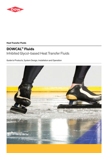
About: Christopher Ian Wright BSc PhD MBATechnologyParameterDescriptionAppearanceYellow liquidGeneral descriptionAromatic hydrocarbonsUsesSynthetic heat transfer fluidTest MethodTypical DataDefined in safety data sheet400Carbon Residue, % weightIP14NDStrong Acid Number, mg KOH/gIP1390.0Total Acid Number, mg KOH/gIP139 0.01Upper operating temperature, CClosed Cup Flash Point, CASTM93113Viscosity, mm2/s (at 40 C)IP712.5Open Flash Point, CASTM92NDFire Point, CASTM92NDASTM D6304 150PQ Analex Method10ASTM D51850Water Content, ppmPQ (X1), Ferrous Debris ScoreFE, ppm less than 5 mTable 1. Typical uses, results and standard test methods for synthetic heat transferfluid. Data is presented as mean SD. # and **, P 0.05 and P 0.0001 when observedresults were compared with expected results using a Chi-Square test. ND, no datareported in safety data sheet.could be of benefit to CSP plants looking to reduce operational downtime,to spread the cost of maintenanceplans and to extend the lifetime of theCSP plant.This report presents the data froma case study where a plant was filledwith a synthetic HTF with a eutecticmixture of diphenyl oxide and biphenyl [5], as is commonly used in anumber of CSP plants. This case demonstrates the importance of SACAduring the building of plants as well ason an ongoing basis.2. Experimental methods2.1. Client heat transfer fluid systemThe current case concerns acompany that was flushing and filling a plant with 100 metric tons of asynthetic HTF.2.2. Synthetic heat transfer fluidGlobal Group was contracted to fillthe HTF system with a synthetic fluidwith a maximal bulk temperature of400 degrees Celsius [5]. Typical properties for the virgin synthetic HTFare reported in Table 1.2.3. HTF system fillThe HTF system was newlybuilt and prior to filling with a virginHTF it was flushed with a fluid toremove all contaminants. The HTFsystem was then filled with a synthetic HTF according to standardisedoperating procedures and managedaccording to the safety data sheet.2.4. Overview of filling procedureOnce the HTF system had beenflushed, the flushing fluid was drainedand the virgin synthetic HTF wasThis case study demonstrates theimportance of sampled and chemicallyanalysed fluids during the building ofconcentrated solar power plants.pumped into the HTF system.Prior to filling the HTF system thelow, high and dump lines for the HTFsystem header tank were identified.They are then checked to ensure theyare clear and that the synthetic HTFcan flow through them. The fillingprocedure was initiated by attachinga suction pump and hose to the dumpvalve on the header tank so that thesynthetic HTF can be drained fromthe HTF system and to allow air to beremoved from the HTF system.The valve from the header tankwas then closed. The synthetic HTFwas then pumped from the lowestpoint in the HTF system, through theheater coils, through the productionline and then to the header tank. Atthis point, the dump valve is openedand filled to its minimum level (i.e.,50 to 200 litres depending on headertank volume) and that the HTFsystem is vented to prevent air fromcirculating through the HTF system, but also to ensure the syntheticfluid is properly vented and that anyunwanted components are removed.Once circulation has been established,the heater is ignited and brought upto 125 C in a step-wise manner. Thisensures that any moisture in the HTFsystem is boiled-off. Once this is done,the HTF system is ready to be run atnormal operational temperature.2.5. Synthetic HTF samplingThe synthetic HTF was sampledwhilst the HTF was in circulation.These samples are then taken to thelaboratory for subsequent chemicalanalysis. During sampling, 500 ml ofthe synthetic HTF was removed fromthe HTF system. This was performedusing a closed sampling device toprevent the synthetic HTF cominginto contact with air and thereforeensuring a representative sample ofthe synthetic HTF was taken. Thistechnique has been presented previously [7, 8].2.6. Chemical analysis of the syntheticHTFAll laboratory analysis was conducted according to ISO14001 [8] andISO17025 [9]. The virgin syntheticHTF was sampled whilst in ISO storage tanks (3 samples were taken) andthen after the HTF system had beenMarch/April 2015 Renewable Energy Focus23
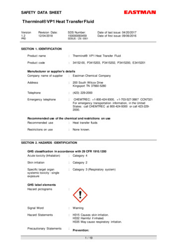
TechnologyPre-fill (n 3)TestTypical Data(i.e., expectedresults)Mean SD(i.e., observedresults)Variance SD(%)ND0.02 0.0116.67 14.43Carbon Residue, % weightStrong Acid Number, mg KOH/g0.00.00 0.000.00 0.00 0.010.04 0.016.61 5.73Closed Cup Flash Point, C113122.00 0.000.00 0.00Viscosity, mm /s (at 40 C)2.5NDNDOpen Flash Point, CND128.67 3.060.04 0.03Fire Point, CND139.33 3.060.03 0.03Water Content, ppm 150209.33 34.36**1.80 1.56PQ (X1), Ferrous Debris Score1010.00 0.000.00 0.00FE, ppm less than 5 m00.00 0.000.00 0.00Total Acid Number, mg KOH/g2Table 2. Results obtained when the synthetic heat transfer fluid was chemicallyanalysed prior to filling the clients HTF system. Data is presented as mean SD. # and **,P 0.05 and P 0.0001 when observed results were compared with expected results usinga Chi-Square test. ND, no data reported in safety data sheet.filled (one sample was taken). Thisenables the values for a typical synthetic HTF to be compared with thosetaken during storage (i.e., pre-fill) andafter filling the HTF system.prior to filling and whilst the synthetic HTF was stored in ISO tanks onthe client’s site) and expected values(i.e., values for the specific syntheticHTF used).2.7. Data analysisMicrosoft Excel 2007 was used tocalculate means, variances and standard deviations with a P-value 0.05taken as an indication of statisticalsignificance being achieved. Specifictests and comparisons conducted asoutlined below.2.7.3. Z-testValues recorded post-fill werecompared with those obtained priorto filling using a Z-test [12]. Thistest compares sample and populationmeans to determine if a significantdifference exists.2.7.1. VarianceVariance was calculated to provide anindication of the reproducibility of testsresults. Variance was calculated usingthis equation: ([the sampled value—thegroup mean]/[the group mean])2 andreported as a percentage [10].2.7.2. Chi-Square testA Chi-Square test [11] was usedto assess the differences betweenobserved values (i.e., those obtained3. ResultsResults are defined according tothe tests defined in the ‘Data analysis’section above.3.1.1. VariancePercentage variance was calculated for all test values and was 2%.Carbon residue and total acid numberhad the highest variance, 16.67% 14.43and 6.61% 5.73, respectively. Pleasesee Table 2.3.1.2. Chi-Square testAnalysis of synthetic HTF revealedno statistical difference (P 0.05)between sampled values and typical values, except for water content(P 0.0001; Chi-Square test) (Table 2).Mean water content, 209.33 ppm, washigher than defined in the safety datasheet (Table 1).3.1.3. Z-testTable 3 comparison of valuesrecorded post-filling with those recorded pre-filling (i.e., whilst stored inISO tanks). Carbon residue decreasedslightly (from 0.02 to 0.01% weight;P 0.05) and water content decreased(from 209.33 to 150.00 ppm; P 0.05,Z test). Thus, water was equivalentto values reported typically for thesynthetic HTF (i.e., estimated to beless than a 1% difference). Total acidnumber remained above the pre-filland typical values for a virgin synthetic HTF (i.e., 0.10 versus 0.04versus 0.01 mg KOH/g, respectively)although this was not significant.4. DiscussionSACA is important in assessing thequality and condition of a syntheticHTF. With virgin HTFs it is imperative that the product is not contaminated during transport and filling ofthe HTF system. Standard operatingprocedures are used to ensure thatthe same process is followed everytime. However, the current casehighlights the importance of SACA,especially with the current syntheticHTF where the main contaminant appears to be water.4.1. Pre-fill and post-fill valuesThis paper further highlights theimportance of SACA of a HTF atevery moment of its lifecycle. Datashows how important it is as a quality control measure, as was the caseduring storage and arrival on site, butalso following a HTF system build.Past research has shown that the overall condition ofa mineral-based heat transfer fluid is better when it issampled and chemically analysed more frequently.24March/April 2015 Renewable Energy Focus
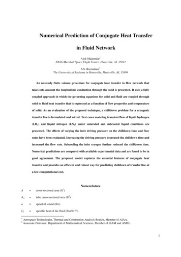
TechnologyThis primarily done to ensure thatthe synthetic HTF is not contaminated during transport or by materialsthat may accumulate in a HTF systemwhilst being built. Ideally, flushingwith GlobalthermTM C1 [13], shouldbe used to clear debris from a systemand avoid contamination of a virginheat transfer fluid.Table 2 shows that water differedsignificantly from expected values.Mean closed flash point temperaturewas 122.00 C and above the value defined for a typical synthetic HTF (i.e.,113 C). This is not an issue as the value was above 113 C and only a problem if closed flash point temperaturedrops below 113 C. In the latter case,the “light-end” fractions would be accumulating in the HTF and would bea sign of thermal degradation. In suchcases, there are a number of optionsfor managing flash point temperature,such as the installation of mobile orpermanently fitted light-end removalkits, which help to keep closed flashpoint temperature stable [10].Mean water level was higher thanreported in the safety data sheet. Itwas 39.6% higher (209 vs. 150 ppm;Table 3). However, the standard operating procedure, briefly outlined in theExperimental Methods, section doeshighlight the importance of removingwater on filling the HTF system. Thiswas the case herein, as post-fillingwith the synthetic HTF water was 150ppm, which is the value defined in thesafety data sheet (Table 3).After the HTF system was filled,total acid number was 1.0 mg KOH/gwhich was higher than the pre-fillvalue (0.04 mg KOH/g) and the typical value ( 0.01 mg KOH/g), althoughthere was no statistical difference.The figure recorded post-fill is has notsignificant impact on the HTF systemas it is normally recommended tomaintain total acid number below 0.2mg KOH/g [14].4.2. VarianceThe data provides insights to thereliability of measurements. This wasnot the primary aim of this study,but it is important as both accurateand regular SACA of a HTF [3] iscritical in assessing both current andfuture HTF condition. Data showsthat the percentage variance was 2%TestTypical DataPre-fill (n 3)Post-fill (n 1)Mean SDMeanCarbon Residue, % weightND0.02 0.010.01†Strong Acid Number, mg KOH/g0.00.00 0.000.00 0.010.04 0.010.10Closed Cup Flash Point, C113122.00 0.00124.90Viscosity, mm /s (at 40 C)2.5NDNDOpen Flash Point, CND128.67 3.06NAFire Point, CND139.33 3.06NAWater Content, ppm 150209.33 34.36150.00‡PQ (X1), Ferrous Debris Score1010.00 0.0010.00FE, ppm less than 5 m00.00 0.000.00Total Acid Number, mg KOH/g2Table 3. Results obtained when the synthetic heat transfer fluid was chemicallyanalysed after being filled. Data is presented as means and mean SD. † and ‡, P 0.05and P 0.005; Z test comparing post-fill with pre-fill. NA, not analysed. ND, no datareported in safety data sheet.4.3. Future researchIt is important to know howreproducible test methods are in thelaboratory. Variance is affected byboth intra and inter-test variation,which is, in turn, potentially influenced by the operator. In this case,the engineer taking the sample. Thecurrent data highlights that there isgenerally a small amount of variance,which suggests that the tests reportshave good reproducibility. However,this is one area where future researchis needed both for mineral-based andsynthetic HTFs.new insight from this report relate tothe fact that the synthetic HTF usedherein is commonly used in the CSPplants and its water content thereforeneeds to be monitored. This is particularly important during its storage toensure it is within the specificationsof the limits defined in the safety datasheet, as well as during any intervention where the HTF system is open toatmosphere as may occur during HTFsystem maintenance, and as part ofan ongoing maintenance program tomonitor the condition of the HTF.Lastly, an ongoing SACA plan isimportant for maintaining the condition of a HTF. This is of potentialvalue to CSP plants, helping to reduceunexpected operational downtimeas well as helping to spread maintenance costs as test results can be usedto predict potential problems andto plan corrective actions at a timethat is most convenient to the client.Finally, to maintain the condition of aHTF and therefore help to extend thelifetime of the components of a CSPplant.5. ConclusionsAcknowledgementsThe key message from this reportis that HTFs need to be analysedroutinely. Indeed, past research hasshown that the overall condition of amineral-based HTF is better when itis sampled and chemically analysedmore frequently. This, therefore, underlines the importance of SACA. TheThe author would like to acknowledge the Global Heat Transfer engineering and technical support teams.for all test parameters prior to filling.This was also true for the virgin synthetic HTF with the only exceptionbeing carbon residue and total acidnumber where percentage variancewas 16.67% and 6.61%, respectively.However, in both cases the valueswere close to zero (mean: carbon,0.02 0.01%; and, total acid number,0.04 0.01 mg KOH/g), and so smallvariations have significantly influenced the calculation for variance.References1. Pidaparthia AS, Prasad NR.India’s first solar thermal parabolic trough pilot power plant.March/April 2015 Renewable Energy Focus25
TechnologySolarPACES 2013. Energy Procedia 2014; 49: 1840 – 18472. Daniel Küser. Solar Report. Concentrating Solar Power (CSP):Outlook on large potentials andthe MENA region. Published 2009.Source: l Accessed: 24thFebruary 2015.3. Australian Solar Institute. Realising the potential of concentratingsolar power in Australia. Reportprepared by IT Power (Australia)PTY LTD in 2011. Source: concentrating-solarpower/ Accessed: 24th February2015.4. Fernandez AG, Cortes M,Fuentealba E, Perez a FJ. Corrosion properties of a ternarynitrate/nitrite molten salt inconcentrated solar technology. Renewable Energy 2015; 80: 177-183.5. Walter WO. Heat transfer technique with organic media. In:Heat transfer media, second ed.Graefelfing, Germany: MariaEich-Stra e; 1997. p. 4–58 [Chapter 2].6. Wright CI, Picot E, BembridgeT. The relationship between thecondition of a mineral-based heattransfer fluid and the frequencythat it is sampled and chemicallyanalysed. Applied Thermal Engineering 2014 (In press).7. Wright CI, Burns A, Jones C.Sampling Hot Heat TransferFluids: Simple Insights for Gaininga Representative Sample International Journal of Engineeringand Innovative Technology 2013; 3:202-204.8. ISO 14001:2004. Environmentalmanagement. Source: http://www.iso.org/iso/iso14000. Accessed:22nd October 2014.9. ISO/IEC 17025:2005. Generalrequirements for the competenceof testing and calibration laboratories. Source: http://www.standards.org/standards/listing/iso 17025. Accessed: 22nd October2014.10. Wright CI. Effective managementof heat transfer fluid flash pointtemperatures using a light-ends removal kit (LERK). Case Studies inThermal Engineering 2014; 4: 9–14.11. Yates F. Contingency table involving small numbers and the 2 test.Supplement to the Journal of theRoyal Statistical Society 1934; 1(2): 217–235.12. Sprinthall RC. Basic StatisticalAnalysis. 9th Edition. PearsonEducation Group. 2011: pp.672.13. GlobalthermTM C1. Source: Globalheattransfer.co.uk. Accessed: 17thFebruary 2015.14. Wright CI. Thermal heat transferfluid problems following a systemflush with caustic and water. CaseStudies in Thermal Engineering2014; 2: 91–94.Save the Datep G z G l G z pzlzGz Gj u G GTGXYSGYWX\l jvSGk SGr 26March/April 2015 Renewable Energy Focuswww.swc2015.org
NEW JOURNALSustainable Energy, Grids and NetworksSustainable Energy, Grids and Networks (SEGAN) is an international peer-reviewedpublication for theoretical and applied research dealing with energy, information gridsand power networks, including smart grids from super to micro grid scales.SEGAN is an interdisciplinary journal which aims to bring together researchers fromacademia and industry from across energy, engineering, computer science,mathematics and energy policy/regulation.SEGAN publishes original articles and short communications, as well as selected reviewarticles by invitation and/or approval of the Editor-in-Chief. Proposals for review articlesand special issues should be submitted to the Editor-in-Chief for consideration.Why publish in Sustainable Energy, Grids and Networks? Online submission and reviewNo submission fee, page charges or online color costs for authorsPublication on ScienceDirect - where more than 15 million scientists,researchers, students and professionals access contentEvery article made freely available on ScienceDirect during the journal's firstyear of publication (until 31 December 2015)Access in the developing world through Research4LifeOpen access option available at a discounted rate of US 1300 (35% discount onUS 2000) for articles submitted by 31 December 2015, and US 1600(20% discount on US 2000) for articles submitted by 31 December 2016Simplified submission process with “Your Paper, Your Way” and “ReferenceSimplification” initiativesBenefit from Article of the Future enhancements, such as AudioSlides (optional)Indexing in ScopusEditor-in-ChiefMario Paolone, Swiss Federal Institute of Technology of Lausanne (EPFL),SwitzerlandEditorial BoardG. Chicco, Politecnico di Torino, ItalyC. Dent, Durham University, UKT. Funabashi, Nagoya University, JapanT. Gomez, Universidad Pontificia Comillas, SpainD.J. Hill, The University of Hong Kong, ChinaJ.-Y. Le Boudec, Swiss Federal Institute of Technology of Lausanne (EPFL),SwitzerlandM. Liserre, Christian-Albrechts-Universität zu Kiel (CAU), GermanyS. Low, California Institute of Technology, USAM. Molinas, Norwegian University of Science & Technology, NorwayP. Panciatici, Réseau de Transport d'Électricité (RTE), FranceJ.A. Peças Lopes, Universidade do Porto, PortugalP. Shenoy, University of Massachusetts at Amherst, USAJ. Sun, Rensselaer Polytechnic Institute, USAV. Terzija, University of Manchester, UKM. Thottan, Bell Laboratories Alcatel-Lucent, USAD. van Hertem, Katholieke Universiteit Leuven, BelgiumA. Wierman, California Institute of Technology, USANow welcoming submissions - find out more atwww.elsevier.com/locate/segan
2.1. Client heat transfer fluid system The current case concerns a company that was flushing and fill-ing a plant with 100 metric tons of a synthetic HTF. 2.2. Synthetic heat transfer fluid Global Group was contracted to fill the HTF system with a synthetic fluid with a maximal bulk temperature of 400 degrees Celsius [5]. Typical prop-