Transcription
Simplify Timing Architectures with Flexible ClocksSilicon Laboratories, Inc., Austin, TXIntroductionDue to the wide diversity of frequency and jitter requirements of the reference clocks required inmodern electronic systems, an assortment of standalone crystal oscillators and fixed-frequencyclock multiplier ICs are typically required to provide a complete timing architecture for both thedata path and control plane. The Si5338 is the industry’s first clock generator capable ofsupporting any-rate frequency synthesis on four independent output clocks. By providing thislevel of frequency flexibility, the Si5338 eliminates the need for fixed-frequency clock generatorsand discrete crystal oscillators.Modern communication, networking, and broadcast video hardware designs use a wide variety ofprocessors, FPGAs, memory, and physical layer transceivers to perform all of the tasks andprocesses required by end applications. The timing architecture in these applications is becomingincreasingly complex due to the growing level of integration required in new designs. Each IC hasits own unique reference clock requirements and multiple clock domains must be carefullymanaged in a single design. Further complicating hardware design, high-speed physical layertransceivers and FPGAs with embedded serializer/deserializers (SERDES) have stringent jitterrequirements to ensure compliance with the end applications’ bit-error rate (BER) specifications.Table 1 shows the broad range of typical clock frequencies required by processors, memory, andphysical layer transceivers in popular communication, networking, and broadcast videoapplications.ComponentProcessors/Network ProcessorsMemoryTypical Reference Clock (MHz)33.33, 66.66, 100, 125, 133.33100, 133, 166, 200, 266Fast Ethernet25Gigabit Ethernet125Fibre ChannelPCI Express 2.0xDSL106.2510035.328, 70.656SONET/SDH OC-3/STM-177.76SONET/SDH OC-12/STM-4155.52HD-SDI74.1758, 74.253G-SDI148.3517, 148.5T11.544E12.048Table 1. Typical Clock Frequencies by ApplicationExamples of traditional timing architectures providing clock generation and clock distribution inthe end application as shown in Figures 1 and 2.Silicon Laboratories, Inc.1
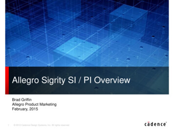
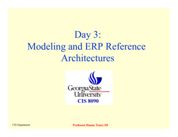
Figure 1. Traditional Timing Architecture in Communication and Networking ApplicationsFigure 2. Traditional Timing Architecture in Broadcast Video ApplicationsGiven the unique requirements of each hardware design, the timing architecture is typicallycustomized for each application using a combination of fixed-frequency clockgenerators/multipliers, discrete crystal oscillators, and muxes. Additional level translator ICs arenecessary when clock format translation is required between the clock generator and the IC.Some applications require multi-protocol high-speed serial data transmission, as shown by theHDTV broadcast video example in Figure 2 above. These applications require multiple oscillatorsand supporting mux circuitry to support the application’s multi-protocol requirements.Silicon Laboratories, Inc.2
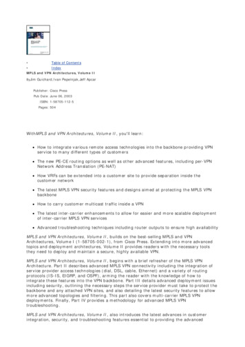
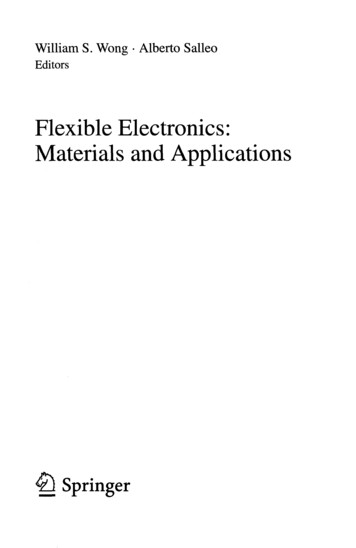
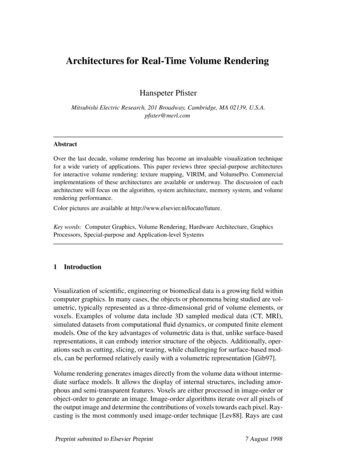
In addition to generating nominal clock frequencies, some applications require frequencymargined clocks that produce references that are at a slight positive or negative offset to thenominal frequency (e.g., 66.6 MHz 5%). These frequency-margined clocks are used duringproduct validation and/or manufacturing test to test the robustness of the design over voltage andtemperature and ensure sufficient setup and hold margin for the critical components in thesystem. Traditionally, frequency margining has been implemented using discrete customfrequency oscillators. Since these additional components are exclusively used during productvalidation and/or manufacturing test and not during normal operation, BOM cost and complexityare increased to support this requirement.Traditional Clock Multiplier ArchitectureTraditional clock generators use a simple integer-N phased-locked loop (PLL)-based architecture.The output clock frequency is a function of the input clock frequency and the PLL divider valuesas shown in the equation and Figure 3:fOUT fIN NP RFigure 3. Traditional Integer-N PLL Clock ArchitectureTraditional single PLL-based IC solutions are suitable for simple integer clock multiplication ofreference inputs or clock generation from crystal inputs. However, many applications requireclock generation of multiple non-integer-related frequencies (e.g., 125 MHz Ethernet and106.25llMHz Fibre Channel). Traditional solutions require that the crystal frequency be changedto support each unique frequency plan. This forces the designer to use one or more customcrystals and multiple clock generator ICs to generate the required set of frequencies, increasingthe cost, complexity and power consumption of the overall solution.New Any-Rate Clock Multiplier Architecture Simplifies DesignRecent advances in mixed-signal analog design have made it possible to provide any-ratefrequency synthesis from a single device. As shown in Figure 4, Silicon Labs’ newest clockarchitecture leverages a fractional-N PLL used in concert with a low-jitter fractional divider termedMultiSynth to produce any-rate frequency synthesis on multiple output clocks. The flagship of thisnew product family is the Si5338 Any-Rate, Any-Output Quad Clock Generator. This technologydramatically simplifies timing architectures by integrating the frequency synthesis capability offour PLLs in a single device, greatly reducing size and power requirements compared totraditional solutions.Silicon Laboratories, Inc.3
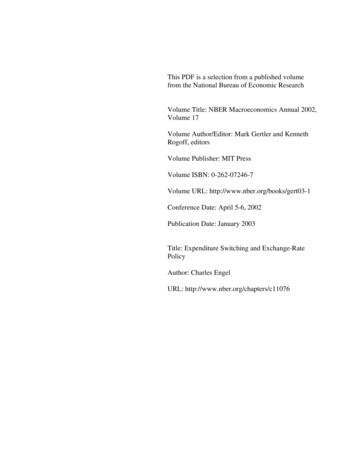
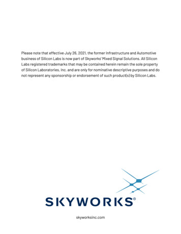
Figure 4. Si5338 Any-Rate, Any-Output Clock Generator ArchitectureMultiSynth TechnologyFigure 5 shows a detailed block diagram of the MultiSynth fractional divider. The Si5338’s lowphase noise, high-frequency VCO supplies a high-frequency output clock to the MultiSynth blockon each of the four independent output paths. The first stage of the MultiSynth architecture is afractional-N divider, which switches seamlessly between the two closest integer divider values toproduce the exact output clock frequency with 0 ppm error. To eliminate phase error generatedby this process, the MultiSynth calculates the relative phase difference between the clockproduced by the fractional-N divider and the desired output clock and dynamically adjusts thephase to match the ideal clock waveform. This novel approach makes it possible to generate anyoutput clock frequency without sacrificing jitter performance. Based on this architecture, eachoutput clock can be individually programmed to generate any frequency from 0.16 to 350 MHz,and select frequencies to 700 MHz. Typical jitter performance enabled by this MultiSynth-basedarchitecture is 1 ps RMS.Figure 5. MultiSynth Architectural OverviewSilicon Laboratories, Inc.4
This MultiSynth-based architecture provides excellent jitter performance as summarized inTable 2.ParameterTest ConditionRandom PhaseJitter (12 kHz to 20MHz)DeterministicPhase JitterTotal Jitter(12 kHz to 20 MHz)Cycle-Cycle JitterPeriod JitterMax Jitter1.5 ps RMSMultiSynth producingfractional divisor15 ps pk-pkMultiSynth producinginteger divisor10 ps pk-pkMultiSynth producingfractional divisor36 ps pk-pkMultiSynth producinginteger divisor20 ps pk-pkN 10,000 cycles50 ps pk-pkCLKIN 25 MHzAll CLKns at 100 MHz30 ps pk-pkTable 2. Si5338 Any-Rate, Any-Output Clock Generator Jitter PerformanceSilicon Laboratories, Inc.5
This level of jitter performance makes it possible to consolidate data path and control planeclocking into a single device as shown in Figures 6 and 7. In addition to dramatically simplifyingBOM cost and complexity, power savings of 50% or more can be realized by migrating to thisnew solution. Board space is also minimized since multiple components are replaced with asingle IC packaged in a small 4x4 mm 24-QFN package.Figure 6. Si5338 Simplifies Communication and Networking Timing ArchitectureFigure 7. Si5338 Simplifies Broadcast Video Timing ArchitectureSilicon Laboratories, Inc.6
Frequency Margining for Board-Level TestFrequency margining is greatly simplified using this approach because the MultiSynth’s fractionaldivider value can be changed dynamically such that the clock output produces a variable clocksource. All frequency transitions are continuous and glitchless. Frequency transitions as small as1 kHz and as large as 10 MHz are possible using this architecture. The frequency of each outputclock can be changed dynamically for any frequency up to 350 MHz. As a result, standalonecrystal oscillators traditionally used for board-level test can be eliminated.Integrated Level TranslationThe signal format of each Si5338 output clock is user-programmable to any of the options listedin Figure 8. This functionality eliminates the need to use external level translators in mostdesigns. Further, use in mixed-supply applications is simplified since every Si5338 output clockhas an independent supply voltage. Each of the device outputs can be programmed to supportany output clock/VDD combination listed below. For example, 1.8 V LVDS, 3.3 V CMOS, and2.5 V LVPECL can be supported simultaneously. The device core operates from a separatesupply voltage operating at 1.8, 2.5 and 3.3 V and is independent of the output clock supplyvoltage (VDDO0 to VDDO3).From AnyTo AnyInput Clock FormatOutput Clock Format/VDDOCMOS1.8, 2.5, or 3.3 V CMOSSSTL1.8, 2.5, or 3.3 V SSTLHSTL1.5 V HSTLLVDS1.8, 2.5, or 3.3 V LVDSLVPECL2.5 or 3.3 V LVPECLHCSL1.8, 2.5, or 3.3 V HCSLFigure 8. Si5338 Provides User-Programmable Output Clock FormatsSummaryThe Si5338 is the industry’s first clock generator capable of supporting any-rate frequencysynthesis on four independent output clocks. By providing this level of frequency flexibility, theSi5338 eliminates the need for fixed-frequency clock generators and discrete crystal oscillators.The device provides outstanding jitter performance of 1 ps RMS, enabling a single device toprovide reference timing for physical layer transceivers as well as processors, networkprocessors, FPGAs and memory. Frequency margining is greatly simplified because crystaloscillators at margined frequencies are no longer required. To further reduce BOM cost andcomplexity, the device supports user-programmable output clock formats, eliminating the need fordiscrete level translators. The best-in-class performance and integration provided by the Si5338greatly simplify timing architectures in communication and broadcast video applications.Silicon Laboratories, Inc.7
SONET/SDH OC-3/STM-1 77.76 SONET/SDH OC-12/STM-4 155.52 HD-SDI 74.1758, 74.25 3G-SDI 148.3517, 148.5 T1 1.544 E1 2.048 Table 1. Typical Clock Frequencies by Application Examples of traditional timing architectures providing clock generation and clock distribution in the end application as shown in Figures 1 and 2.