Transcription
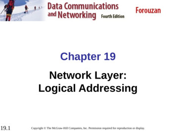
Chapter 19Network Layer:Logical Addressing19.1Copyright The McGraw-Hill Companies, Inc. Permission required for reproduction or display.
19-1 IPv4 ADDRESSESAn IPv4 address is a 32-bit address that uniquely anduniversally defines the connection of a device (forexample, a computer or a router) to the Internet.Topics discussed in this section:Address SpaceNotationsClassful AddressingClassless AddressingNetwork Address Translation (NAT)19.2
NoteAn IPv4 address is 32 bits long.19.3
NoteThe IPv4 addresses are uniqueand universal.19.4
NoteThe address space of IPv4 is232 or 4,294,967,296.19.5
Figure 19.1 Dotted-decimal notation and binary notation for an IPv4 address19.6
NoteNumbering systems are reviewed inAppendix B.19.7
Example 19.1Change the following IPv4 addresses from binarynotation to dotted-decimal notation.SolutionWe replace each group of 8 bits with its equivalentdecimal number (see Appendix B) and add dots forseparation.19.8
Example 19.2Change the following IPv4 addresses from dotted-decimalnotation to binary notation.SolutionWe replace each decimal number with its binaryequivalent (see Appendix B).19.9
Example 19.3Find the error, if any, in the following IPv4 addresses.Solutiona. There must be no leading zero (045).b. There can be no more than four numbers.c. Each number needs to be less than or equal to 255.d. A mixture of binary notation and dotted-decimalnotation is not allowed.19.10
NoteIn classful addressing, the addressspace is divided into five classes:A, B, C, D, and E.19.11
Figure 19.2 Finding the classes in binary and dotted-decimal notation19.12
Example 19.4Find the class of each address.a. 00000001 00001011 00001011 11101111b. 11000001 10000011 00011011 11111111c. 14.23.120.8d. 252.5.15.111Solutiona. The first bit is 0. This is a class A address.b. The first 2 bits are 1; the third bit is 0. This is a class Caddress.c. The first byte is 14; the class is A.d. The first byte is 252; the class is E.19.13
Table 19.1 Number of blocks and block size in classful IPv4 addressing19.14
NoteIn classful addressing, a large part ofthe available addresses were wasted.19.15
Table 19.2 Default masks for classful addressing19.16
NoteClassful addressing, which is almostobsolete, is replaced with classlessaddressing.19.17
Example 19.5Figure 19.3 shows a block of addresses, in both binaryand dotted-decimal notation, granted to a small businessthat needs 16 addresses.We can see that the restrictions are applied to this block.The addresses are contiguous. The number of addressesis a power of 2 (16 24), and the first address is divisibleby 16. The first address, when converted to a decimalnumber, is 3,440,387,360, which when divided by 16results in 215,024,210.19.18
Figure 19.3 A block of 16 addresses granted to a small organization19.19
NoteIn IPv4 addressing, a block ofaddresses can be defined asx.y.z.t /nin which x.y.z.t defines one of theaddresses and the /n defines the mask.19.20
NoteThe first address in the block can befound by setting the rightmost32 n bits to 0s.19.21
Example 19.6A block of addresses is granted to a small organization.We know that one of the addresses is 205.16.37.39/28.What is the first address in the block?SolutionThe binary representation of the given address is11001101 00010000 00100101 00100111If we set 32 28 rightmost bits to 0, we get11001101 00010000 00100101 0010000or205.16.37.32.This is actually the block shown in Figure 19.3.19.22
NoteThe last address in the block can befound by setting the rightmost32 n bits to 1s.19.23
Example 19.7Find the last address for the block in Example 19.6.SolutionThe binary representation of the given address is11001101 00010000 00100101 00100111If we set 32 28 rightmost bits to 1, we get11001101 00010000 00100101 00101111or205.16.37.47This is actually the block shown in Figure 19.3.19.24
NoteThe number of addresses in the blockcan be found by using the formula232 n.19.25
Example 19.8Find the number of addresses in Example 19.6.SolutionThe value of n is 28, which means that numberof addresses is 2 32 28 or 16.19.26
Example 19.9Another way to find the first address, the last address, andthe number of addresses is to represent the mask as a 32bit binary (or 8-digit hexadecimal) number. This isparticularly useful when we are writing a program to findthese pieces of information. In Example 19.5 the /28 canbe represented as11111111 11111111 11111111 11110000(twenty-eight 1s and four 0s).Finda. The first addressb. The last addressc. The number of addresses.19.27
Example 19.9 (continued)Solutiona. The first address can be found by ANDing the givenaddresses with the mask. ANDing here is done bit bybit. The result of ANDing 2 bits is 1 if both bits are 1s;the result is 0 otherwise.19.28
Example 19.9 (continued)b. The last address can be found by ORing the givenaddresses with the complement of the mask. ORinghere is done bit by bit. The result of ORing 2 bits is 0 ifboth bits are 0s; the result is 1 otherwise. Thecomplement of a number is found by changing each 1to 0 and each 0 to 1.19.29
Example 19.9 (continued)c. The number of addresses can be found bycomplementing the mask, interpreting it as a decimalnumber, and adding 1 to it.19.30
Figure 19.4 A network configuration for the block 205.16.37.32/2819.31
NoteThe first address in a block isnormally not assigned to any device;it is used as the network address thatrepresents the organizationto the rest of the world.19.32
Figure 19.5 Two levels of hierarchy in an IPv4 address19.33
Figure 19.6 A frame in a character-oriented protocol19.34
NoteEach address in the block can beconsidered as a two-levelhierarchical structure:the leftmost n bits (prefix) definethe network;the rightmost 32 n bits definethe host.19.35
Figure 19.7 Configuration and addresses in a subnetted network19.36
Figure 19.8 Three-level hierarchy in an IPv4 address19.37
Example 19.10An ISP is granted a block of addresses starting with190.100.0.0/16 (65,536 addresses). The ISP needs todistribute these addresses to three groups of customers asfollows:a. The first group has 64 customers; each needs 256addresses.b. The second group has 128 customers; each needs 128addresses.c. The third group has 128 customers; each needs 64addresses.Design the subblocks and find out how many addressesare still available after these allocations.19.38
Example 19.10 (continued)SolutionFigure 19.9 shows the situation.Group 1For this group, each customer needs 256 addresses. Thismeans that 8 (log2 256) bits are needed to define eachhost. The prefix length is then 32 8 24. The addressesare19.39
Example 19.10 (continued)Group 2For this group, each customer needs 128 addresses. Thismeans that 7 (log2 128) bits are needed to define eachhost. The prefix length is then 32 7 25. The addressesare19.40
Example 19.10 (continued)Group 3For this group, each customer needs 64 addresses. Thismeans that 6 (log264) bits are needed to each host. Theprefix length is then 32 6 26. The addresses areNumber of granted addresses to the ISP: 65,536Number of allocated addresses by the ISP: 40,960Number of available addresses: 24,57619.41
Figure 19.9 An example of address allocation and distribution by an ISP19.42
Table 19.3 Addresses for private networks19.43
Figure 19.10 A NAT implementation19.44
Figure 19.11 Addresses in a NAT19.45
Figure 19.12 NAT address translation19.46
Table 19.4 Five-column translation table19.47
Figure 19.13 An ISP and NAT19.48
19-2 IPv6 ADDRESSESDespite all short-term solutions, address depletion isstill a long-term problem for the Internet. This andother problems in the IP protocol itself have been themotivation for IPv6.Topics discussed in this section:StructureAddress Space19.49
NoteAn IPv6 address is 128 bits long.19.50
Figure 19.14 IPv6 address in binary and hexadecimal colon notation19.51
Figure 19.15 Abbreviated IPv6 addresses19.52
Example 19.11Expand the address 0:15::1:12:1213 to its original.SolutionWe first need to align the left side of the double colon tothe left of the original pattern and the right side of thedouble colon to the right of the original pattern to findhow many 0s we need to replace the double colon.This means that the original address is.19.53
Table 19.5 Type prefixes for IPv6 addresses19.54
Table 19.5 Type prefixes for IPv6 addresses (continued)19.55
Figure 19.16 Prefixes for provider-based unicast address19.56
Figure 19.17 Multicast address in IPv619.57
Figure 19.1819.58Reserved addresses in IPv6
Figure 19.19 Local addresses in IPv619.59
Chapter 20Network Layer:Internet Protocol20.1Copyright The McGraw-Hill Companies, Inc. Permission required for reproduction or display.
20-1 INTERNETWORKINGIn this section, we discuss internetworking, connectingnetworks together to make an internetwork or aninternet.Topics discussed in this section:Need for Network LayerInternet as a Datagram NetworkInternet as a Connectionless Network20.2
Figure 20.1 Links between two hosts20.3
Figure 20.2 Network layer in an internetwork20.4
Figure 20.3 Network layer at the source, router, and destination20.5
Figure 20.3 Network layer at the source, router, and destination (continued)20.6
NoteSwitching at the network layer in theInternet uses the datagram approach topacket switching.20.7
NoteCommunication at the network layer inthe Internet is connectionless.20.8
20-2 IPv4The Internet Protocol version 4 (IPv4) is the deliverymechanism used by the TCP/IP protocols.Topics discussed in this section:DatagramFragmentationChecksumOptions20.9
Figure 20.4 Position of IPv4 in TCP/IP protocol suite20.10
Figure 20.5 IPv4 datagram format20.11
Figure 20.6 Service type or differentiated services20.12
NoteThe precedence subfield was part ofversion 4, but never used.20.13
Table 20.1 Types of service20.14
Table 20.2 Default types of service20.15
Table 20.3 Values for codepoints20.16
NoteThe total length field defines the totallength of the datagram including theheader.20.17
Figure 20.7 Encapsulation of a small datagram in an Ethernet frame20.18
Figure 20.8 Protocol field and encapsulated data20.19
Table 20.4 Protocol values20.20
Example 20.1An IPv4 packet has arrived with the first 8 bits as shown:01000010The receiver discards the packet. Why?SolutionThere is an error in this packet. The 4 leftmost bits (0100)show the version, which is correct. The next 4 bits (0010)show an invalid header length (2 4 8). The minimumnumber of bytes in the header must be 20. The packet hasbeen corrupted in transmission.20.21
Example 20.2In an IPv4 packet, the value of HLEN is 1000 in binary.How many bytes of options are being carried by thispacket?SolutionThe HLEN value is 8, which means the total number ofbytes in the header is 8 4, or 32 bytes. The first 20 bytesare the base header, the next 12 bytes are the options.20.22
Example 20.3In an IPv4 packet, the value of HLEN is 5, and the valueof the total length field is 0x0028. How many bytes ofdata are being carried by this packet?SolutionThe HLEN value is 5, which means the total number ofbytes in the header is 5 4, or 20 bytes (no options). Thetotal length is 40 bytes, which means the packet iscarrying 20 bytes of data (40 20).20.23
Example 20.4An IPv4 packet has arrived with the first few hexadecimaldigits as shown.0x45000028000100000102 . . .How many hops can this packet travel before beingdropped? The data belong to what upper-layer protocol?SolutionTo find the time-to-live field, we skip 8 bytes. The time-tolive field is the ninth byte, which is 01. This means thepacket can travel only one hop. The protocol field is thenext byte (02), which means that the upper-layer protocolis IGMP.20.24
Figure 20.9 Maximum transfer unit (MTU)20.25
Table 20.5 MTUs for some networks20.26
Figure 20.10 Flags used in fragmentation20.27
Figure 20.11 Fragmentation example20.28
Figure 20.12 Detailed fragmentation example20.29
Example 20.5A packet has arrived with an M bit value of 0. Is this thefirst fragment, the last fragment, or a middle fragment?Do we know if the packet was fragmented?SolutionIf the M bit is 0, it means that there are no morefragments; the fragment is the last one. However, wecannot say if the original packet was fragmented or not. Anon-fragmented packet is considered the last fragment.20.30
Example 20.6A packet has arrived with an M bit value of 1. Is this thefirst fragment, the last fragment, or a middle fragment?Do we know if the packet was fragmented?SolutionIf the M bit is 1, it means that there is at least one morefragment. This fragment can be the first one or a middleone, but not the last one. We don’t know if it is the firstone or a middle one; we need more information (the valueof the fragmentation offset).20.31
Example 20.7A packet has arrived with an M bit value of 1 and afragmentation offset value of 0. Is this the first fragment,the last fragment, or a middle fragment?SolutionBecause the M bit is 1, it is either the first fragment or amiddle one. Because the offset value is 0, it is the firstfragment.20.32
Example 20.8A packet has arrived in which the offset value is 100.What is the number of the first byte? Do we know thenumber of the last byte?SolutionTo find the number of the first byte, we multiply the offsetvalue by 8. This means that the first byte number is 800.We cannot determine the number of the last byte unlesswe know the length.20.33
Example 20.9A packet has arrived in which the offset value is 100, thevalue of HLEN is 5, and the value of the total length fieldis 100. What are the numbers of the first byte and the lastbyte?SolutionThe first byte number is 100 8 800. The total length is100 bytes, and the header length is 20 bytes (5 4), whichmeans that there are 80 bytes in this datagram. If the firstbyte number is 800, the last byte number must be 879.20.34
Example 20.10Figure 20.13 shows an example of a checksumcalculation for an IPv4 header without options. Theheader is divided into 16-bit sections. All the sections areadded and the sum is complemented. The result isinserted in the checksum field.20.35
Figure 20.13 Example of checksum calculation in IPv420.36
Figure 20.14 Taxonomy of options in IPv420.37
20-3 IPv6The network layer protocol in the TCP/IP protocolsuite is currently IPv4. Although IPv4 is well designed,data communication has evolved since the inception ofIPv4 in the 1970s. IPv4 has some deficiencies thatmake it unsuitable for the fast-growing Internet.Topics discussed in this section:AdvantagesPacket FormatExtension Headers20.38
Figure 20.15 IPv6 datagram header and payload20.39
Figure 20.16 Format of an IPv6 datagram20.40
Table 20.6 Next header codes for IPv620.41
Table 20.7 Priorities for congestion-controlled traffic20.42
Table 20.8 Priorities for noncongestion-controlled traffic20.43
Table 20.9 Comparison between IPv4 and IPv6 packet headers20.44
Figure 20.17 Extension header types20.45
Table 20.10 Comparison between IPv4 options and IPv6 extension headers20.46
20-4 TRANSITION FROM IPv4 TO IPv6Because of the huge number of systems on theInternet, the transition from IPv4 to IPv6 cannothappen suddenly. It takes a considerable amount oftime before every system in the Internet can move fromIPv4 to IPv6. The transition must be smooth to preventany problems between IPv4 and IPv6 systems.Topics discussed in this section:Dual StackTunnelingHeader Translation20.47
Figure 20.18 Three transition strategies20.48
Figure 20.19 Dual stack20.49
Figure 20.20 Tunneling strategy20.50
Figure 20.21 Header translation strategy20.51
Table 20.11 Header translation20.52
Chapter 21Network Layer:Address Mapping,Error Reporting,and Multicasting21.1Copyright The McGraw-Hill Companies, Inc. Permission required for reproduction or display.
21-1 ADDRESS MAPPINGThe delivery of a packet to a host or a router requirestwo levels of addressing: logical and physical. We needto be able to map a logical address to its correspondingphysical address and vice versa. This can be done byusing either static or dynamic mapping.Topics discussed in this section:Mapping Logical to Physical AddressMapping Physical to Logical Address21.2
Figure 21.1 ARP operation21.3
Figure 21.2 ARP packet21.4
Figure 21.3 Encapsulation of ARP packet21.5
Figure 21.4 Four cases using ARP21.6
NoteAn ARP request is broadcast;an ARP reply is unicast.21.7
Example 21.1A host with IP address 130.23.43.20 and physical addressB2:34:55:10:22:10 has a packet to send to another hostwith IP address 130.23.43.25 and physical addressA4:6E:F4:59:83:AB. The two hosts are on the sameEthernet network. Show the ARP request and replypackets encapsulated in Ethernet frames.SolutionFigure 21.5 shows the ARP request and reply packets.Note that the ARP data field in this case is 28 bytes, andthat the individual addresses do not fit in the 4-byteboundary. That is why we do not show the regular 4-byteboundaries for these addresses.21.8
Figure 21.5 Example 21.1, an ARP request and reply21.9
Figure 21.6 Proxy ARP21.10
Figure 21.7 BOOTP client and server on the same and different networks21.11
NoteDHCP provides static and dynamicaddress allocation that can bemanual or automatic.21.12
21-2 ICMPThe IP protocol has no error-reporting or errorcorrecting mechanism. The IP protocol also lacks amechanism for host and management queries. TheInternet Control Message Protocol (ICMP) has beendesigned to compensate for the above two deficiencies.It is a companion to the IP protocol.Topics discussed in this section:Types of MessagesMessage FormatError Reporting and QueryDebugging Tools21.13
Figure 21.8 General format of ICMP messages21.14
NoteICMP always reports error messages tothe original source.21.15
Figure 21.9 Error-reporting messages21.16
NoteImportant points about ICMP error messages: No ICMP error message will be generated inresponse to a datagram carrying an ICMP errormessage. No ICMP error message will be generated for afragmented datagram that is not the first fragment. No ICMP error message will be generated for adatagram having a multicast address. No ICMP error message will be generated for adatagram having a special address such as127.0.0.0 or 0.0.0.0.21.17
Figure 21.10 Contents of data field for the error messages21.18
Figure 21.11 Redirection concept21.19
Figure 21.12 Query messages21.20
Figure 21.13 Encapsulation of ICMP query messages21.21
Example 21.2Figure 21.14 shows an example of checksum calculationfor a simple echo-request message. We randomly chosethe identifier to be 1 and the sequence number to be 9.The message is divided into 16-bit (2-byte) words. Thewords are added and the sum is complemented. Now thesender can put this value in the checksum field.21.22
Figure 21.14 Example of checksum calculation21.23
Example 21.3We use the ping program to test the server fhda.edu. Theresult is shown on the next slide. The ping program sendsmessages with sequence numbers starting from 0. Foreach probe it gives us the RTT time. The TTL (time tolive) field in the IP datagram that encapsulates an ICMPmessage has been set to 62. At the beginning, ping definesthe number of data bytes as 56 and the total number ofbytes as 84. It is obvious that if we add 8 bytes of ICMPheader and 20 bytes of IP header to 56, the result is 84.However, note that in each probe ping defines the numberof bytes as 64. This is the total number of bytes in theICMP packet (56 8).21.24
Example 21.3 (continued)21.25
Figure 21.15 The traceroute program operation21.26
Example 21.4We use the traceroute program to find the route from thecomputer voyager.deanza.edu to the server fhda.edu. Thefollowing shows the result:The unnumbered line after the command shows that thedestination is 153.18.8.1. The packet contains 38 bytes: 20bytes of IP header, 8 bytes of UDP header, and 10 bytes ofapplication data. The application data are used bytraceroute to keep track of the packets.21.27
Example 21.4 (continued)The first line shows the first router visited. The router isnamed Dcore.fhda.edu with IP address 153.18.31.254.The first round-trip time was 0.995 ms, the second was0.899 ms, and the third was 0.878 ms. The second lineshows the second router visited. The router is namedDbackup.fhda.edu with IP address 153.18.251.4. Thethree round-trip times are also shown. The third lineshows the destination host. We know that this is thedestination host because there are no more lines. Thedestination host is the server fhda.edu, but it is namedtiptoe.fhda.edu with the IP address 153.18.8.1. The threeround-trip times are also shown.21.28
Example 21.5In this example, we trace a longer route, the route toxerox.com (see next slide). Here there are 17 hopsbetween source and destination. Note that some roundtrip times look unusual. It could be that a router was toobusy to process the packet immediately.21.29
Example 21.5 (continued)21.30
21-3 IGMPThe IP protocol can be involved in two types ofcommunication: unicasting and multicasting. TheInternet Group Management Protocol (IGMP) is oneof the necessary, but not sufficient, protocols that isinvolved in multicasting. IGMP is a companion to theIP protocol.Topics discussed in this section:Group ManagementIGMP Messages and IGMP OperationEncapsulationNetstat Utility21.31
Figure 21.16 IGMP message types21.32
Figure 21.17 IGMP message format21.33
Table 21.1 IGMP type field21.34
Figure 21.18 IGMP operation21.35
NoteIn IGMP, a membership report is senttwice, one after the other.21.36
NoteThe general query message does notdefine a particular group.21.37
Example 21.6Imagine there are three hosts in a network, as shown inFigure 21.19. A query message was received at time 0; therandom delay time (in tenths of seconds) for each groupis shown next to the group address. Show the sequence ofreport messages.SolutionThe events occur in this sequence:a. Time 12: The timer for 228.42.0.0 in host A expires,and a membership report is sent, which is received bythe router and every host including host B whichcancels its timer for 228.42.0.0.21.38
Example 21.6 (continued)b. Time 30: The timer for 225.14.0.0 in host A expires, anda membership report is sent which is received by therouter and every host including host C which cancels itstimer for 225.14.0.0.c. Time 50: The timer for 238.71.0.0 in host B expires,and a membership report is sent, which is received bythe router and every host.d. Time 70: The timer for 230.43.0.0 in host C expires,and a membership report is sent, which is received bythe router and every host including host A whichcancels its timer for 230.43.0.0.21.39
Figure 21.19 Example 21.621.40
Figure 21.20 Encapsulation of IGMP packet21.41
NoteThe IP packet that carries an IGMPpacket has a value of 1 in its TTL field.21.42
Table 21.2 Destination IP addresses21.43
Figure 21.21 Mapping class D to Ethernet physical address21.44
NoteAn Ethernet multicast physical addressis in the range01:00:5E:00:00:00 to 01:00:5E:7F:FF:FF.21.45
Example 21.7Change the multicast IP address 230.43.14.7 to anEthernet multicast physical address.SolutionWe can do this in two steps:a. We write the rightmost 23 bits of the IP address inhexadecimal. This can be done by changing therightmost 3 bytes to hexadecimal and then subtracting8 from the leftmost digit if it is greater than or equal to8. In our example, the result is 2B:0E:07.21.46
Example 21.7 (continued)b. We add the result of part a to the starting Ethernetmulticast address, which is 01:00:5E:00:00:00. Theresult is21.47
Example 21.8Change the multicast IP address 238.212.24.9 to anEthernet multicast address.Solutiona. The rightmost 3 bytes in hexadecimal is D4:18:09. Weneed to subtract 8 from the leftmost digit, resulting in54:18:09.b. We add the result of part a to the Ethernet multicaststarting address. The result is21.48
Figure 21.22 Tunneling21.49
Example 21.9We use netstat (see next slide) with three options: -n, -r,and -a. The -n option gives the numeric versions of IPaddresses, the -r option gives the routing table, and the -aoption gives all addresses (unicast and multicast). Notethat we show only the fields relative to our discussion.“Gateway” defines the router, “Iface” defines theinterface.Note that the multicast address is shown in color. Anypacket with a multicast address from 224.0.0.0 to239.255.255.255 is masked and delivered to the Ethernetinterface.21.50
Example 21.9 (continued)21.51
21-4 ICMPv6We discussed IPv6 in Chapter 20. Another protocolthat has been modified in version 6 of the TCP/IPprotocol suite is ICMP (ICMPv6). This new versionfollows the same strategy and purposes of version 4.Topics discussed in this section:Error ReportingQuery21.52
Figure 21.23 Comparison of network layers in version 4 and version 621.53
Table 21.3 Comparison of error-reporting messages in ICMPv4 and ICMPv621.54
Table 21.4 Comparison of query messages in ICMPv4 and ICMPv621.55
Chapter 22Network Layer:Delivery, Forwarding,and Routing22.1Copyright The McGraw-Hill Companies, Inc. Permission required for reproduction or display.
22-1 DELIVERYThe network layer supervises the handling of thepackets by the underlying physical networks. Wedefine this handling as the delivery of a packet.Topics discussed in this section:Direct Versus Indirect Delivery22.2
Figure 22.1 Direct and indirect delivery22.3
22-2 FORWARDINGForwarding means to place the packet in its route toits destination. Forwarding requires a host or a routerto have a routing table. When a host has a packet tosend or when a router has received a packet to beforwarded, it looks at this table to find the route to thefinal destination.Topics discussed in this section:Forwarding TechniquesForwarding ProcessRouting Table22.4
Figure 22.2 Route method versus next-hop method22.5
Figure 22.3 Host-specific versus network-specific method22.6
Figure 22.4 Default method22.7
Figure 22.5 Simplified forwarding module in classless address22.8
NoteIn classless addressing, we need atleast four columns in a routing table.22.9
Example 22.1Make a routing table for router R1, using theconfiguration in Figure 22.6.SolutionTable 22.1 shows the corresponding table.22.10
Figure 22.6 Configuration for Example 22.122.11
Table 22.1 Routing table for router R1 in Figure 22.622.12
Example 22.2Show the forwarding process if a packet arrives at R1 inFigure 22.6 with the destination address 180.70.65.140.SolutionThe router performs the following steps:1. The first mask (/26) is applied to the destination address.The result is 180.70.65.128, which does not match thecorresponding network address.2. The second mask (/25) is applied to the destinationaddress. The result is 180.70.65.128, which matches thecorresponding network address. The next-hop addressand the interface number m0 are passed to ARP forfurther processing.22.13
Example 22.3Show the forwarding process if a packet arrives at R1 inFigure 22.6 with the destination address 201.4.22.35.SolutionThe router performs the following steps:1. The first mask (/26) is applied to the destinationaddress. The result is 201.4.22.0, which does notmatch the corresponding network address.2. The second mask (/25) is applied to the destinationaddress. The result is 201.4.22.0, which does notmatch the corresponding network address (row 2).22.14
Example 22.3 (continued)3. The third mask (/24) is applied to the destinationaddress. The result is 201.4.22.0, which matches thecorresponding network address. The destinationaddress of the packet and the interface number m3 arepassed to ARP.22.15
Example 22.4Show the forwarding process if a packet arrives at R1 inFigure 22.6 with the destination address 18.24.32.78.SolutionThis time all masks are applied, one by one, to thedestination address, but no matching network address isfound. When it reaches the end of the table, the modulegives the next-hop address 180.70.65.200 and interfacenumber m2 to ARP. This is probably an outgoing packagethat needs to be sent, via the default router, to someplaceelse in the Internet.22.16
Figure 22.7 Address aggregation22.17
Figure 22.8 Longest mask matching22.18
Example 22.5As an example of hierarchical routing, let us considerFigure 22.9. A regional ISP is granted 16,384 addressesstarting from 120.14.64.0. The regional ISP has decidedto divide this block into four subblocks, each with 4096addresses. Three of these subblocks are assigned to threelocal ISPs; the second subblock is reserved for future use.Note that the mask for each block is /20 because theoriginal block with mask /18 is divided into 4 blocks.The first local ISP has divided its assigned subblock into8 smaller blocks and assigned each to a small ISP. Eachsmall ISP provides services to 128 households, each usingfour addresses.22.19
Example 22.5 (continued)The second local ISP has divided its block into 4 blocksand has assigned the addresses to four largeorganizations.The third local ISP has divided its block into 16 blocksand assigned each block to a small organization. Eachsmall organization has 256 addresses, and the mask is /24.There is a sense of hierarchy in this configuration. Allrouters in the Internet send a packet with destinationaddress 120.14.64.0 to 120.14.127.255 to the regional ISP.22.20
Figure 22.9 Hierarchical routing with ISPs22.21 pag
The ISP needs to distribute these addresses to three groups of customers as follows: a. The first group has 64 customers; each needs 256 addresses. b. The second group has 128 customers; each needs 128 addresses. c. The third group has 128 customers; each needs 64 addresses. Design the subblocks and find out how many addresses