Transcription
White PaperArchitecture StudyBroadband Network GatewayRe-Architecting the Broadband Network Gateway(BNG) in a Network Functions Virtualization (NFV)and Cloud Native WorldAuthorsPadraig ConnollyIntel Platform Applications EngineerAndrew DuignanIntel Platform Solutions ArchitectShivapriya HiremathIntel Platform Applications EngineerTommy LongIntel Software ArchitectJasvinder SinghIntel Software EngineerEoin WalshIntel Platform Solutions ArchitectExecutive SummaryThe ever-growing consumer demand for more bandwidth and services for lessmoney has been driving service provider networks to their economic limit for someyears now. In addition, communications service providers (CoSPs) need to supportmultiple access technology types (xDSL, PON, FWA, and DOCSIS) while makingbetter use of existing fiber networks and increasing service delivery performance,all against a backdrop of declining revenues. With customer data traffic estimatedto grow at a 26 percent rate (year over year) from 2017 to 2023,1 future networkingsolutions must show a path to solving tomorrow’s data compound-annual-growthrate (CAGR) challenge in a cost-effective and scalable way.Pushing the boundary of performance requires the latest and greatest technologyalong with deploying this technology in a holistic and easy-to-use way. This paperproposes the following set of design principles for taking solutions based on Intel architecture processors and network functions virtualization (NFV) to the next levelof performance and network automation by utilizing the following: Optimized server configuration Software “run-to-completion” model Intelligent I/O packet and flow distribution Independent scaling of the control and user planes Hierarchical quality of service considerations Deploying using Cloud Native Networking FundamentalsFollowing these principles, Intel has demonstrated nearly 661 Gbps² of routingRFC2544 (zero packet loss) performance for a virtual broadband network gateway(vBNG) running on a single 3rd Gen Intel Xeon Scalable processor server. Thispaper describes this effort and proposes a vBNG architecture for building networkinfrastructure and network functions to better take advantage of the underlyinginfrastructure and address the challenge of the data CAGR.Table of ContentsExecutive Summary . . . . . . . . . . . . . . 1To complement the shift of the Broadband data plane into a virtual ecosystem,this paper also puts forward a deployment architecture using the containerorchestration engine Kubernetes (K8s).Broadband Network Gateway . . . . . 2Reference Application Pipeline. . . . 2New Architectural Proposal andReasoning . . . . . . . . . . . . . . . . . . . . . . . 3Orchestration of the BNG . . . . . . . . . 7Performance Benchmarking⁷. . . . . . 8Summary . . . . . . . . . . . . . . . . . . . . . . . . 9Appendix . . . . . . . . . . . . . . . . . . . . . . . 10Figure 1. Example of a Network Connecting Clients to a Data Center
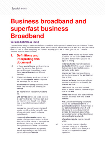
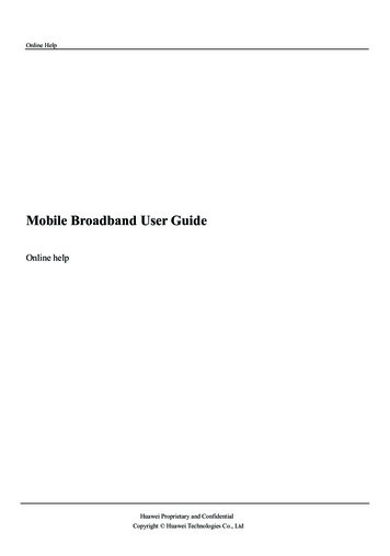
2. Architecture Study Broadband Network Gatewayhave seen larger swathes of data being pushed onto the ISPnetwork by users, broadband users are still overwhelminglynet consumers of data. In recent years, data and contentcreation has reduced the gap between upstream anddownstream bandwidth usage.Upstream Processing StagesThe Intel reference pipeline implements the upstreamprocessing stages shown in Figure 3 and described inthe following:Figure 2. Virtual Broadband Network Gateway (vBNG)Control and Data Plane BlocksBroadband Network GatewayThe BNG, aka broadband remote access server (BRAS), isthe network edge aggregation point used by subscribersto access the Internet service provider (ISP) network.Through the BNG, subscribers connect to the ISP network todownload Internet originating traffic and ISP services (e.g.,web, voice, data, and video).The vBNG is a virtualized software instantiation of whatis typically a large, ASIC-based, fixed-function applianceusually located in a central office or metro point ofpresence (PoP).Reference Application PipelineEach generation of Intel technologies (e.g., CPU, NIC, SSD,FPGAs, and accelerators) brings new opportunities toimprove performance and quality of experience (QoE) forusers. Showing how to take advantage of these technologies,Intel builds reference pipelines, like the representative stagesof vBNG control and data plane functions shown in Figure 2.The control plane is responsible for subscriber authenticationand management, including monthly usage service accessand data plane configuration, based on subscriber profiles.The upstream data plane manages the flow of traffic fromusers’ home routers to the ISP network. The averagepacket size for upstream traffic is generally smaller than fordownstream traffic, and the amount of upstream traffic isnormally five to eight times less than downstream traffic.While applications like Instagram, Snapchat, and Periscope,Figure 3. Uplink Packet Flow StagesPacket Rx (Receive): The data plane development kit (DPDK)poll mode driver (PMD) is used to receive bursts of framesfrom the network interface controller (NIC) port and sendthem directly into an uplink thread to begin vBNG packetprocessing, described in the next stages.Access Control Lists: The DPDK Access Control List (ACL)library is used to apply an ordered list of filters (e.g., masks,ranges, etc.) to the frame. These comprise permit and denyfilters, and all filters are evaluated per packet.Flow Classification: The DPDK Flow Classification Library isused to identify the session and classify the packet based onselected fields (e.g., 5 tuple).Metering Policing: The DPDK Traffic Metering and PolicingAPI is used to apply a two-rate, three-color marking andpolicing scheme to the traffic.DSCP Rewrite: This stage supports the optional classificationof the traffic type and rewrite of the IP differentiated servicescode point (DSCP) field to map the stream to a networksupported class of service (CoS).NAT: Optionally, NAT 44 is performed to convert privateaddresses to public addresses.Routing: Access network encapsulations are stripped fromdata plane packets, and the packets are routed to the correctcore network interface for transmission. Any core networkencapsulations, such as MPLS, are applied either here or inthe packet Tx block.Packet Tx (Transmit): The DPDK PMD is used to send burstsof frames to the NIC port.
3. Architecture Study Broadband Network GatewayFigure 4. Downlink Packet Flow StagesThe downstream data plane handles the flow of traffic anddata from the Internet and ISP network to the end user. Itmanages and schedules traffic to users attached to the BNG.The downstream function optimizes bandwidth and resourceusage to maximize users QoE, based on user tariff class andtraffic priorities. The goal of the ISP is to ensure all theirsubscribers are receiving services to the highest standardwhile maximizing the utility of the network infrastructure. By2022, global IP video traffic is forecast to grow four-fold from2017 to 2022, a CAGR of 29 percent,³ and this trend will driveup the average packet size of the downstream link.Downstream Processing StagesThe Intel reference pipeline implements the downstreamprocessing stages shown in Figure 4 and described inthe following:Packet Rx: The DPDK PMD receives frames from the NICport and sends them directly into a downlink thread to beginvBNG packet processing, described in the next stages.Access Control Lists (ACL): The DPDK Access Control List(ACL) library is used to apply an ordered list of filters (e.g.,masks, ranges, etc.) to the frame. This stage blocks reversepath forwarding.NAT: Optionally, NAT 44 is performed to convert publicaddresses to private addresses.Traffic Management: Each packet runs through a hierarchicalQoS (HQoS) block to ensure high priority packets areprioritized when transmitting packets to the access network.It supports scalable five-level hierarchical construction (port,subport, pipe, traffic class and queues) of traffic shapers andschedulers to guarantee the bandwidth for different servicesused by subscribers. Each pipe is assigned to a singlesubscriber.Routing: Access network encapsulations are stripped fromdata plane packets, and the packets are routed to the correctdata network interface for transmission. Any access networkencapsulations, such as VLAN, PPPoE etc., are applied eitherhere or in the packet Txblock.Packet Tx: Using a DPDK polled mode driver (PMD), bursts offrames are transmitted to the NIC port.New Architectural Proposal and ReasoningIn order to effectively deploy a BNG workload on ageneral-purpose server, the following architectural andimplementation aspects should be considered:Implementing a Run to Completion ModelOne of the key considerations when designing a softwarebased BNG is ensuring performance scalability per thispaper’s opening problem statement. The BNG shouldbe assigned the minimal number of resources needed tosupport the current number of active subscribers at any timeof the day. This means the BNG must be able to scale both upand down based on the current workload.The Intel reference BNG pipeline uses a run to completionmodel to process the uplink and downlink pipelines. As aresult, all pipeline functions executed on a packet are runon the same core. This has advantages in that packets donot have to move between cores, thereby minimizing cachemisses and overall latency. A direct result of this designpattern is that an individual vBNG instance cannot scale outbeyond a single core. Scaling beyond a single core is done bycreating a new vBNG instance that runs on a different core.The NIC is programmed (using custom headers supportedby the Comms DDP package) on the fly to direct specificsubscribers to each new individual vBNG instance (More onthis further on in the paper).The combination of a run to completion model and a singlecore running a single vBNG instance eliminates the needfor the orchestrator to understand the internal operationof the vBNG application to scale. The orchestrator can scalecapacity up or down by increasing or decreasing the numberof CPU cores assigned to the BNG deployment (5 vCPUs perInstance with K8s), enabling linear scalability across a givenserver. The orchestrator can optimize resource utilizationwhen it is furnished with information regarding the numberof subscribers (for a known traffic profile) that a single coreinstance can support, which may vary by CPU SKU.Separating Uplink and Downlink ProcessingCPU resource usage by the BNG uplink and downlinkpipelines are not symmetric since the downlink normallyrequires more cycles per packet due to inherently largerpacket sizes. In order to effectively schedule a BNG, theIntel reference pipeline splits the uplink and downlink into
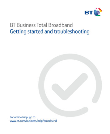
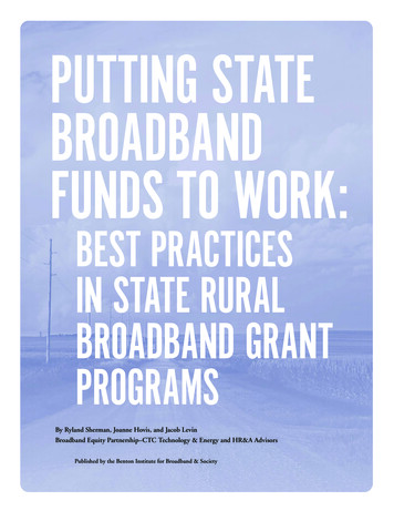
4. Architecture Study Broadband Network GatewayFigure 5. CPU Core Allocation Example for 16vBNGsInstances Running per Sockettwo separate containers that can be instantiated and thenscheduled separately. This separation provides greaterflexibility in scheduling and CPU resource usage. Forexample, a downlink pipeline can be assigned a full physicalcore (two sibling hyper-threaded cores) while an uplinkpipeline might only require half a physical core (one hyperthread core). Figure 5 shows how the CPU resources of a dualsocket server could be partitioned when running sixteenvBNG instances per socket in a Docker only configuration(i.e not using K8s). Each pipeline can report telemetryindividually, and the telemetry database can be used tomaintain all relevant usage statistics. It is also worth notingwhilst uplink and downlink pipelines are deployed asseparate DPDK applications and containers this paper putsforward the architecture of coupling them together usingKubernetes and its pod deployment API.Figure 6. BNG Downlink Container Using A Single SR-IOV VFfor Both Rx and TxAssigning a Single I/O Connection per PipelineBalancing I/O on the ServerThe Intel reference pipeline should be run on a BNGdataplane server connected to a basic leaf switch thatcan route both access and data network traffic. With thissetup,the switch routes uplink traffic coming from the accessnetwork ports to the BNG ports for processing and routesreturning packets from BNG uplink pipelines to the datanetwork ports. The flow is reversed for downlink traffic.As mentioned previously, the amount of uplink traffic isincreasing over time, but it is generally only an eighth ofthe downlink traffic in a wireline network. Therefore, a BNGthat uses separate,dedicated physical ports for access anddata network port connections is likely to under utilize theavailable I/O bandwidth of the uplink ports. Instead, sharingphysical ports on a NIC between upstream and downstreamtraffic allows I/O bandwidth to be fully utilized. As a vBNGinstance is split into two separate pipeline applications,each pipeline only handles traffic for a single direction. Alltraffic is routed to and from the server through the simple L2switch, such that each pipeline does not require dedicatedaccess and data network ports. The server effectively needsjust a single I/O connection on which it receives traffic fromthe switch and returns processed traffic to the switch forforwarding, as shown in Figure 6.With dual socket servers, internal connections such asPlatform Controller Hubs (PCHs) and SATA controllers arecommonly connected to CPU 0, as shown on the left side ofFigure 7. This can result in an uneven distribution of PCIe I/Obandwidth between the CPUs, with most of the bandwidthbeing connected to CPU 1. To balance the bandwidth, theIntel vBNG application runs control plane functions on CPU0 and data plane functions on CPU 1, as shown on the rightside of Figure 7.The routing of subscriber traffic to a vBNG instance isdone via a dedicated Single Root Input/Output Virtualization(SR-IOV) connection that can send arriving packets tothe vBNG in accordance with its SR-IOV switch(with DDP).SR-IOV allows a single physical NIC port to be split andshared among multiple pipeline instances, each with its ownI/O port i.e a Virtual Function (VF). SR-IOV also providesflexibility in the use of physical NICs, such as dedicating aphysical NIC to downlink traffic only or sharing a NIC betweenuplink and downlink traffic. As NIC speeds hit 100 gigabit, it isexpected that downlink and uplink traffic will share the samephysical NIC and these principals influence the deploymentarchitecture of the vBNG today.Figure 7. Balancing I/O on a Server
5. Architecture Study Broadband Network GatewayFigure 8. Device Config Function WorkflowWhen deploying a BNG on a general-purpose server, itis important to ensure there is enough I/O bandwidth tofully utilize the available CPU resources on the platform(i.e., the aim is to be CPU bound and not I/O bound). Theadvent of Control and User Plane Separation (CUPS)⁴ forBNG enables an entire server to be dedicated to runningthe BNG data plane. All data processing is localized to asingle socket for performance efficiency, which necessitatesan equal amount of I/O to be connected to each socket toachieve optimal performance. The provisioning of 2x16 or4x8 lane PCIe Gen 4 (16 GT/s) slots on each socket providesa total I/O bandwidth of 800 Gbps on the server, equallybalanced across the two sockets (see the Appendix for serverconfiguration details).(DCF) technology. DCF sets Flow Rules through a trustedVF allowing the user to keep the SR-IOV Physical Functionbound to the Linux driver for management and metriccollection as seen in Figure 8. When distributing flows in theIntel Ethernet Network Adapter E810 it must be noted thatfor distributing flows amongst VFs the SR-IOV Switch is usedand for distributing flows amongst Queues, Flow Director(FDIR) or Receive Side Scaling (RSS) is used. In the BNGdeployment, flows are distributed using VFs thus that is thefocus of this paper. Further information on RSS and FDIR canbe found in other Intel Telco white papers.Distributing Flows Via a Network Interface Card (NIC)As described above each BNG instance has a set numbervCPUs processing subscriber traffic. Some form of distributeris required in order split out the subscriber flows among thevCPUs. This distributor task can be performed in softwareusing dedicated cores, but there are several disadvantagesto this approach. First, this distributer function can becomea performance bottle neck as all flows must pass throughthis software function. Second, having one or many coresdedicated to performing distribution reduces the amountof CPU cycles available to perform the actual BNG workloadprocessing, thus reducing the number of BNG subscribers theserver can handle.These disadvantages can be overcome by distributing theflows in the NIC to either SR-IOV VFs or Queues in the PMD,which eliminates the software bottle neck, reduces latencythrough the system, and provides the BNG the CPU cores andcycles that otherwise would be used by the distributor task.Assigning a Single I/O Connection per PipelineDevice Config Function (DCF)The Intel Ethernet Network Adapter E810 is a NIC thatsupports flow distribution using the Device Config FunctionFigure 9. DDP Packages for E810 NICDynamic Device PersonalizationAlongside DCF is Dynamic Device Personalization (DDP)⁶which allows the SR-IOV Switch to filter on more packetheader types than the default amount without reloading theEthernet Controller NVM image. For the BNG applicationdeployment, the Telecommunication (Comms) DynamicDevice Personalization (DDP) Package is used (Figure 9).Once added this package allows the Ethernet Controller tosteer traffic based on PPPoE header fields to the ControlPlane offload VF. The DDP PPPoE profile enables the NICto route packets to specific VFs and queues (Figure 10) basedon the unique PPPoE header fields (described more in thenext section).
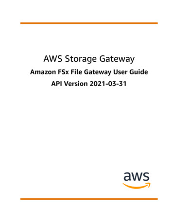
6. Architecture Study Broadband Network GatewayFigure 10. NIC Routes Packets to Virtual Functions based on PPPoE and DHCP Packet HeadersForwarding Control Plane PacketsConsidering HQoSFor control plane traffic, like PPPoE session setup or PPPoElink control packets, the BNG data plane must identify andforward these packets to the control plane for processing. Ina traditional BNG, the control plane and the data plane arelocated in the same place and a local software queue is usedto move packets between them. With the advent of CUPS,the control plane and the corresponding data plane is mostlikely located in different physical locations in the network. Inthis case, the BNG data plane needs to pass control packetsto the control plane by generating a physical link to forwardthem. As can be seen in Figure 10, the Intel Ethernet NetworkAdapter E810 is able to identify these control packets usingthe Comms DDP package and forward them to a separate VFsand queues (I/O), relieving the data plane of this task. TheComms DDP package enables the Intel NIC to recognize thesecontrol plane packets and forward them the control plane.Figure 11 gives a higher level view of how this works with theBNG application deployment.Hierarchical QoS is a function that is implemented withinthe vBNG downlink pipeline. It ensures traffic priority ispreserved when traffic coming from the core network isscheduled for transmission on the reduced bandwidth accessnetwork pipe to a subscriber, and the available bandwidth ona given port is shared efficiently across all users. The HQoSscheduler can either be implemented in NIC if support isavailable or as a software function in packet processingpipeline before the transmit function. As discussedpreviously, each downlink pipeline has a single virtualfunction connection for I/O. The following sections describethree models for implementing HQoS:Figure 12. Software-Only HQOS ModelFigure 11. Control Plane Traffic ForwardingSoftware-Only ModelA software-only model fully implements HQoS schedularin software. As shown in Figure 12, each vBNG downlinkpipeline is apportioned part of the port’s overall bandwidthand shapes its traffic to that sub port rate. The advantage ofthis method is no hardware support is needed, and allowsto scale the HQoS scheduler instances with downlink packetprocessing pipelines. The disadvantage of this method isunused bandwidth in one vBNG instance cannot be sharedwith another instance, which may lead to sub-optimal use ofthe port’s bandwidth.Hardware/Software Hybrid ModelA hybrid model can be used when the resources on the NIC(e.g. queues, scheduler/shaping nodes) are not sufficient to
7. Architecture Study Broadband Network GatewayvBNG is the CUPs architecture and Cloud-Native Networking.CUPS described earlier makes the control and user planetwo separate entities that communicate over a set API. Thissection will mainly focus on how the vBNG achieves CloudNative Networking at high throughput rates. Also referencedin other Intel wireline papers are the following conventionsthat a telco application needs to abide by to consideritself a CNF: Figure 13. Hardware/Software Hybrid Modelfully implement the HQoS scheduler as shown in Figure 13.In this model, each BNG instance implements somescheduling/shaping levels of the hierarchy in softwareand remaining levels are implemented in NIC. Decision ondividing the hierarchy between software and hardwaredepends upon the number of NIC resources. As anadvantage, this model allows unused bandwidth fromone BNG instance to be shared among other instances. Highly Performant – The CNF must take advantage ofEnhanced Platform Awareness (EPA) features to ensurelow latency and high throughput.Agile Placement – The CNF must allow for flexibleplacement to be allowed to deploy on any EPA featureready platform and must be generic to the EPAinfrastructure provided beneath.Lifecycle Management – Using automatic telemetryaware controllers, the CNF must ensure that it canscale resources under increasing workloads and retractresources under decreasing workloads.Highly Available – The CNF must always present highavailability to its required workload by engrainingextreme fault tolerance into the component architectureto meet the Service Level Agreement of almost zerodowntime. The CNF must also utilise the HA schemato maintain interfaces for quick and simple serviceupgrades without any effect on the service it provides.Observability – The CNF must ensure all network andperformance metrics of workloads are exposed throughan easy to consume platform allowing for rapid networkdebugging and modification.Date Plane DeploymentFigure 14. Full HQoS Offload ModelFull HQoS Offload ModelA full HQoS offload model requires a NIC that can supportfull offload of HQoS processing from all vBNG instances, asshown in Figure 14. A major advantage of this model is theCPU does not play a role in HQoS, freeing up CPU cyclesfor other pipeline blocks.The proposed vBNG architecture supports all three ofthese models, depending on the capabilities of theunderlying hardware.Orchestration of the BNGThe vBNG architecture proposed in this paper does not limithow a vBNG instance is virtualized. For example, either fullvirtual machine (VM) virtualization or Linux containers canbe used. When a vBNG comprises of two individual pipelines,deploying each in a separate container may/can be betteras it is a light weight virtualization option, compared todeploying in virtual machines. Containers also allow for morerapid initialization and recovery of instances following theconvention in network deployments of high availability.For the deployment of a vBNG instance in both the referenceapplication and this paper, a pair of containers is launchedby the orchestration engine Kubernetes. This section willfurther discuss how this is achieved under the umbrellaconvention of a Cloud-Native Network Function (CNF). Thetwo biggest influences on the design and deployment of theThe deployment of the vBNG follows a strict microservicemodel where each element of application deployment isseparated into the smallest possible execution unit that willnot affect performance. As can be seen in Figure 15, the fullData Plane deployment (Not Control Plane) is separated into3 components: BNG DP Management- In short, this section is seen as the interfacebetween the Control Plane and the Data Plane in afull CUPS deployment- This section is responsible for: Receiving Data Plane Configuration (PFCP Agent) Setting and storing the Data PlaneConfiguration (etcd) Retrieving telemetry data from the DataPlane instances Managing the scale of vBNG Pods/Instances BNG Data Plane- Discussed previously this section is responsible for: The vBNG forwarding pods Uplinkand Downlink The Telnet etcd agent (This agent is seen to beshared between the BNG DP Management and BNGData Plane but physically it is deployed in theData Plane)
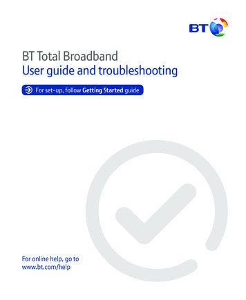
8. Architecture Study Broadband Network GatewayFigure 15. Full Micro Service Architecture of a BNG Deployment Infrastructure- This section uses K8’s CPU and Device Managersto provide all the EPA features required by the CNFspecification for performant throughput- This section is responsible for: The K8s Kubelet (Manages container state ofthe Node) The K8s CPU Manager( Supplies exclusive vCPUsto the vBNG Containers) The SRIOV Device Plugin (Supplies SR-IOV VirtualFunctions on demand to the vBNG Containers) The Topology Manager (Ensures resources receivedfrom the host are NUMA Topology aligned) The Unified Flow Stack (Uses DCF and DDP to setSR-IOV Switch rules allowing scale based onsubscriber header fields)Control Plane DeploymentThe Control Plane used in the BNG deployment is built byBiSDN. This follows the same micro service architectureas the other components in the BNG deployment in whicheach element is deployed as a container entity. For theBNG deployment, the BNG Control Plane may be deployedon the same cluster as the BNGDP Management and BNGFigure 16. 1:N mapping of Control Plane to Data Plane onmultiple clustersData Plane or in a separate remote cluster for commandingmultiple BNG clusters. If deployed in the same cluster itutilizes the same container network interfaces (CNIs) aswith other BNG components; see Figure 16. If the networkoperations engineer requires the BNG Control Plane to beplaced in a remote cluster, it would be expected of them toset up something like the K8s Ingress Controller on the DataPlane Cluster to ensure external BNG Control Plane access isregulated and load balanced for the DPPFCP Agent to receiveand parse messages.Deployment OverviewBy combining all of the architecture proposals previouslydiscussed, it is possible to build a scalable, orchestratable,and CUPS-enabled BNG solution that efficiently uses theI/O and compute resources of an Intel processor-basedserver. This solution can help CoSPs address the need todeliver ever-increasing bandwidth at lower cost, as outlinedat the beginning of the paper. Figure 17 provides a high leveloverview of a full CUPS deployment alongside all ingress andegress Broadband traffic.Figure 17. Scalable CUPS-Enabled BNG Architecture
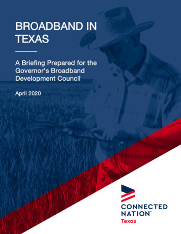
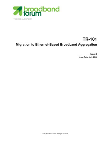
9. Architecture Study Broadband Network GatewayFigure 18. Performance Testing Pipeline BlocksSummaryFigure 19. Intel Xeon Processor-Based Server (Dual Socket)Throughput Running Various vBNG InstancesPerformance Benchmarking⁷Performance measurements on the blue pipeline blocksshown in Figure 18 were taken on a dual socket server withIntel Hyper-Threading Technology (Intel HT Technology)enabled, Enhanced Intel SpeedStep Technology andIntel Turbo Boost Technology disabled. The same trafficprofile was applied to all instances (4,000 flows, downlink/uplink packet size 650B), and the cumulative throughput(downlink uplink) across all instances was measured. Theoptional grey blocks were not enabled.Figure 19 shows the throughput of an Intel Xeon processor-based server with two 3rd Gen Intel Xeon Scalableprocessors 6338N running vBNG container instances. Thethroughput scales very effectively as we deploy from fourthrough thirty two vBNG instances with increment of fourinstances.With thirty two instances deployed, the throughput is661Gbps when using RFC2544 test methodology with0.001% packet loss. This is achieved using 96 data processingcores (1.5 cores per instance for thirty two instances). Allresources used by the BNG application are local to the socket.It is found to be I/O bound but not CPU bound.Something to be noted with these results is that they wererun in a “Docker Only” configuration whereby K8’s was notused to scale up and down instances.The future viability of NFV-based networking equipmentrunning on general-purpose servers hinges on the abilityto service ever-increasing traffic volume in a cost-effectivemanner. This paper presents architectural considerationsand benchmarking data that demonstrate the huge potentialfor NFV-based packet processing. In addition, CoSPs candeliver network connectivity and new services from the edgeof the network using a combination of BNG and service-edgesolutions. By rethinking how virtualized network functionsare created and deployed, new possibilities arise, such as:1. Redefining the unit of performance from the number ofVMs or containers to the number of cores that deliver anearly linear increase in uplink and downlink throughput2. Creating a model that is virtual network function (VNF)architecture agnostic (i.e., VM, container, or baremetal).3. Generating a deterministic price per home model thatstays predictable with the traffic CAGR.4. Increasing network availability by converting the largemonolith of systems to distributed systems, whichenables CoSPs to better manage fault domains andcontain affected areas, thus minimizing connectionstorms and outage times.5. Creating a multifunction edge infrastructure that canaddress both NFV and services.Raw BNG performance is not one single data point answerbut a discussion on network location, subscriber density,average bandwidth per subscriber, and traffic CAGR overth
Broadband Network Gateway The BNG, aka broadband remote access server (BRAS), is the network edge aggregation point used by subscribers to access the Internet service provider (ISP) network. Through the BNG, subscribers connect to the ISP network to download Internet originating traffic and ISP services (e.g., web, voice, data, and video).