Transcription
IFE/P6-22Overview on Neutronics, Safety and Radiological Protection of HiPERFacilityR. Juárez 1,2), J. Sanz 1,2), J. M. Perlado 2)1) Departamento de Ingeniería Energética, UNED, Madrid, Spain2) Instituto de Fusión Nuclear, UPM, Madrid, SpainE-mail contact of main autor: rafael.juarez@upm.esAbstract. The design of the HiPER facility is in its conceptual phase. The design of the facility includesdifferent shields facing the dose rates that will arise from the operation. We have studied the implications of apreliminary proposal of design from the standpoint of shielding requirements. The reference case is consideredto be the most exigent irradiation scenario conceived for HiPER 4a. 100MJ neutron yields per shot, with 100shots at 10 Hz in a single burst, one burst every month. The expected lifetime of the facility for this scenario is20 years. We have computed the prompt dose rates (PDR) and residual dose rates (RDR) delivered to theworkers/public during the operation and in the period between bursts; we also computed the prompt dosedelivered to the Final Optic Assembly (FOA), as a sensitive part of the facility. The shields that have beenproposed behave reasonably well, creating free-restriction areas outside the target bay, and allowing manualmaintenance 36 hours after the shutdown in some stays. The FOA receives a dose rate 30 times lower in thepresence of the FOA shield. We compute the quantities with the same design undergoing a softer irradiationscenario, resulting a waiting time to access to the restricted area shorter than one day. The FOA receives 20times lower dose rates. We have also considered different materials for the tubes which transport the beams, asthey are the main responsible for the RDRs. The choice of material for the reaction chamber is discussed forcommercial and reduced-activation steels, with regards to waste management performance.1. IntroductionThe HiPER project phase 4a is considered to become an engineering machine. The presenceof neutrons derived from the experiments requires the study of doses and of the activation ofthe components of the facility to identify necessities of shields regarding with people andequipment.The most exigent irradiation planning proposed has been 100 MJ of neutron yield per shot.Up to 100 shots could happen in a single burst at 10 Hz. With one month between bursts, upto 12 burst per years could be attained. The lifetime of the facility considered is 20 years forthis irradiation scenario. It represents 1.2·105 MJ/yr, 1000 times higher than it is expected tohappen in NIF [1]. The operation of the facility will spread neutrons and photons, giving riseto PDRs to people and equipment. Shields are placed within the target bay to protect peopleagainst the PDR, and a special shield is conceived to reduce the PDR delivered to the FOA.With this reference design, explained in section 2, we have also computed the activation ofthe components, and RDRs between bursts due to this activation. These results offer an ideaof which could be the shield requirementsAs some other irradiation scenarios are considered in HiPER, we have calculated the samequatities for another sequence of shots. A more realistic irradiation scenario consists in 20 MJshots, with no more than 5 events with neutron generation in a 100 non-explosive shots burst.One burst would happen every week, limited to 50 bursts per year. 30 years of lifetime areassumed in the irradiation scenario, which accounts for 5·103 MJ/yr. For this softer scenariowe have calculated the same quantities than for the exigent and reference one.After this study, we focus on two specific problems: RDR to people (workers and public)inside the target bay and choice of material for the reaction chamber.
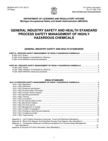
IFE/P6-22The RDR shows to be dominated by the activation of the tubes [2], so in order to reduce it, wehave investigate different materials for these tubes, seeking a reduction of activation. Theactivation of the chamber is a quantity to consider to choice the material for the reactionchamber. We study the waste management of two different reaction chambers, one built ofcommercial stainless austenitic steel, and the other built of a reduced-activation ferritic steel(RAFS). Both compositions are assumed to present reasonable impurities concentrations.2. Facility DesignThe facility design consists in two groups of components: basic components and shields. Thebasic components are: reaction chamber, beam tubes, renewable optics and FOA. Given thenecessity to protect some basic components and workers/public against radiation, severalshields are placed to pursue a reduction of delivered dose.2.1 Basic ComponentsStarting from the center of the facility, the first component that neutrons find is the reactionchamber. It is a spherical shell assumed to be made of SS304L steel [3]. This steel iscommercial option of good welding capabilities. It has been considered for fusion before [4],and reasonable impurities concentrations are measured. It inner radius is 500cm and it is 10cmthick. It presents 48 cylindrical penetrations, distributed in 6 rings. In the section 4.4, there isa study on the impact of building the reaction chamber of EUROFER[5]. This RAFS isconceived to exhibit an attractive behavior from the waste management standpoint, giving riseto lower dose rates than commercial steels.After the reaction chamber, there are the 48 beam tubes. They present a squared section of100cm side and 1cm of thick. The vacuum is maintained inside these tubes to allow the beamto travel to the center of the reaction chamber. Two groups of tubes are separated by the FOAshield. Inside the first group of beam tubes, it is found the renewable lenses, and the secondtubes, after the FOA shield, host the FOA, another group of lenses. The beam tubes are builtof SS304L. The physical requirements for these tubes suggest the proposal of other materialsas Al5083 [6] or PVC to build these tubes. It is sought to reduce the RDR between bursts, assome hours after the shutdown, the beam tubes are the main responsible for that dose [2].Al5083 has been used in NIF to build the reaction chamber, and its radiological behavior hasbeen studied before [7], being lower than that for SS304 in some periods of time after theshutdown. Its impurities level is well measured [6]. The PVC in its pure formulation is a verylow activation material, due to the low Z number of its components [-CH2-CHCl-]n.Although the PVC requires additives to perform different tasks, we have assumed a pure PVCmatrix as it is not defined which type of PVC would be suitable. If it were chosen, furtheranalysis would be made on the impact of the additives.The optics is divided in two groups: the renewable lenses, and the FOA. The renewable lensesface the detonations, so they undergo high radiation doses. They are expected to be replacedfrequently. The lenses are 75cm side squares of 5cm thick. The FOA presents 6 opticalelements per beamline, accounting for 288 elements. There mirrors, frequency converters andfocusing lenses [8]. All the optical elements are made of pure silica. The disposition of thebasic components can be found in figure 1.2.2 ShieldsThe shields are added to protect against the radiation the people and the FOA. Starting fromthe center, the first one is the chamber shield. It is a 40cm thick spherical shell built of borated
IFE/P6-22gunite. It is in contact with the chamber, and it is also present in NIF. It pursues to reduce theactivation of components and the RDR derived from the activation of the chamber betweenburst. As the beams should go through, it presents the same penetration as the chamber does.Figure 1: Preliminary proposal design of HiPER facilityAt 16.5m from the center of the chamber, the beam presents a focus, and a beam spot of 2mmradius. There they are placed two different shields to protect the FOA with regards to theprompt dose. The first one is a 2 meter thick standard concrete [6] spherical shield, with 48penetrations aligned with the beam tubes. Inside the penetrations, in-tube shields are placed.They are concrete cylinders of 50cm radius, presenting a pinhole of 2mm radius to allow thebeam to cross through. The impact of the absence of this shield is studied in [2].Finally, it is placed a bioshield which delimits the target bay. It consists in a 2 meter thickconcrete cylindrical shell, with 25m of inner radius and 50m of height. All theses shieldsdelimit areas where dose rates delivered to people will be computed to evaluate the shields.The areas will be named 1, 2 and 3 going from the inner part of the facility to the exterior.Thus, the zone 1 is the stay between the chamber shield and the FOA shield, where thechamber, the rims, the chamber shield, the tubes1 and the renewable lenses are located. Afterthe FOA, but before the bioshield there is the zone 2, where tubes2 and FOA are located. Thezone 3 stands for the two first meters after the bioshield and represents the exterior of thetarget bay. The disposition of shields is also found in figure 1.3. Computational tools and methodologyThe starting point is the geometry design, accomplished with MCAM [9]. Due the complexityof the geometry, an auxiliary code as MCAM has been necessary. The second one is
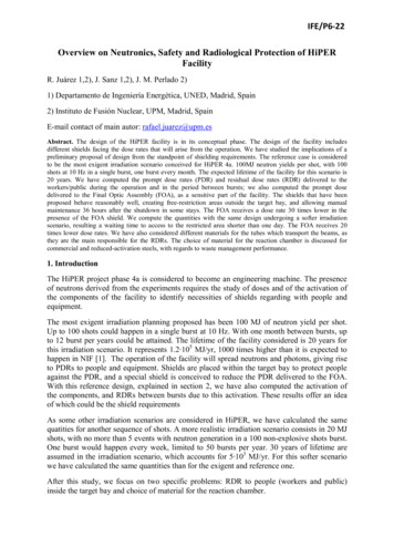
IFE/P6-22performed with MCNPX [10] and the libraries la150n, endf60 and endl92, and fullycorresponds to the operation of the facility. We transport the outcoming neutrons with a givenspectrum [11] with MCNPX and compute the following quantities: PDR to people, PDR tothe FOA and neutron fluxes with Vitamin-J energy structure. The dose rate to people iscalculated with the flux-to-dose conversion coefficient given in ICRP74 for Ambient DoseEquivalent [12]. The PDRs to the FOA are calculated through the deposited energy.With the neutron fluxes, we compute the activation of all the components of the facility forthe exact pulsed irradiation scheme. It is performed with the isotopic inventory code ACAB[13] and the EAF libraries [14]. We also compute the parameters for the waste management:Waste Disposal Rate (WDR) [15], Contact Dose Rate (CDR), and Clearance [14]. Thiscorresponds with the third step. Once the activation is known the fourth and last step starts.The resulting gamma decay computed with ACAB is transported with MCNPX, and the RDR(ICRP74) to people is calculated. This shows the time evolution of the dose rate levels withinthe zones delimited by the shields.The limits for the dose rates to people are taken form ICRP90 [16]. For the workers,20mSv/yr or 10 Sv/h; for the public, 1mSv/yr. All the results expressed in this study arecomputed with a relative error lower than 2%. The RDR are computed as average doses in thewhole stays where people could access, i.e., zones 1, 2 and 3.4. Results and analysis4.1 Reference DesignThe problematic associated to the reference design with the reference and exigent irradiationscenario can be found extended in [2]. The PDRs to the people in the different areas anddelivered to FOA are shown in table 1.Table 1: PDR to people and FOA in the reference scenario and reference designNeutronsPhotonsTotalZone 1 (Sv/yr)3.46·1058.70·1033.55·105Zone 2 (Sv/yr)32.00.62832.6Zone 3 (Sv/yr)1.69·10-71.88·10-62.05·10-6FOA (Gy/yr)34.114.148.2The zones 1 and 2 are areas of exclusion during the operation of the machine. The zone 3 fitsthe limit for the public, being free of restriction even during the operation. The RDRs in thezones 1 and 2 are depicted in the figure 2. The RDR in zone 3 is not shown because it is lowerthan workers limit from the shutdown. The time evolution of the RDR between bursts isshown after the 1st and after the 239th, the last burst. A difference of a factor of 4 isencountered [2]. The manual maintenance limit, 10 Sv/h is never reached in zone 1, so onlyremote operation is allowed inside. In zone 2, after the first burst, 36 hours after theshutdown, this limit is reached, allowing the entrance of workers. As burst happens,radioisotopes accumulate. The limit is crossed, but given the assumptions and simplifications,it is though that manual maintenance will be allowed during the whole lifetime of the facility,after a careful study and planning. Details of the activities set in that stay are necessary andcollective doses may be performed. The contribution of different components to the RDR isfound in [2]
IFE/P6-22Time Evolution of the Residual Dose .0E 031.0E 021.0E 011.0E 001.0E-011.0E-021.0E-031.0E-041.0E-051.0E-061.0E 001.0E 011.0E 021.0E 031.0E 04Time (s)1.0E 051.0E 061.0E 07Figure 2: Time evolution of the RDR in the zones 1 and 2 in the reference scenario, after the first and the lastburstThe RDR is so high in the zone 1 that is does not seem reasonable to try to reach the manualmaintenance limit. In zone 2, from the shutdown to 10 minutes, the dominant contributor tothe RDR is the FOA. After 10 minutes, the tubes are the main responsible for the RDR. Thisis the reason why, in order to minimize the RDR, the approach that we propose is to changethe material for the tubes, trying to find a material which would result less activated in the 1month time period between bursts.4.2 Irradiation ScenariosThe reference irradiation scenario based on 100MJ-100shots-1month-20years is the mostexigent scenario conceived up to the moment in the phase 4a of HiPER. However, there is amore realistic proposal of sequence of shots. It consists in 20MJ neutron yields, with 5 eventsin a 100 non-explosive shots per bursts at 10 Hz (explosions occur at 0.5 Hz). A burst happensevery week, with no more than 50 bursts per year. The lifetime of the facility is assumed to beextended to 30 years. The consequences of the reduction of irradiation are explored in thissubsection, by comparing with the reference case. The total PDR (neutrons and photons) tothe people and optics is shown in table 2;Table 2: Comparison of PDR to people and FOA with reference design and two irr
to be the most exigent irradiation scenario conceived for HiPER 4a. 100MJ neutron yields per shot, with 100 shots at 10 Hz in a single burst, one burst every month. The expected lifetime of the facility for this scenario is 20 years. We have computed the prompt dose rates (PDR) and residual dose rates (RDR) delivered to the workers/public during the operation and in the period between bursts .