Transcription
AIR CONDITIONINGTECHNICAL HANDBOOKA Selection of Useful InformationFor Single/Twin Split, Super Multi, Modular MultiSuper Modular Multi, Mini SMMS, Super Heat Recovery,Digital Inverter Models and Super Digital Inverter.TOSHIBA24 Hour Technical Helpline: 0870 843 0333Page 1 of 72Ver. 11.5
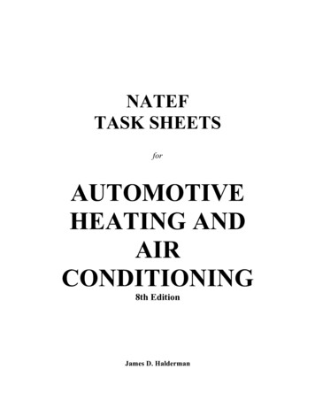
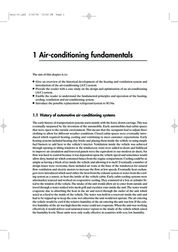
Make Up Of Model NumberRAV ProductsRAV–165KH -PERAV Light Commercial RangeRAS Small Office / DomesticE CE markedP Made in PlymouthApprox Duty (x 1000 BTU)Blank Single Phase Power Supply8 Three Phase Power SupplyGenerationRAV use numbers i.e. 0,1,2,3,4,5RAS use letters i.e. U,E,S,YBlank Cool Only (RAV) / HP (inv)*H HP (RAV) / Cool Only (inv)*N Chassis TypeL Console TypeS Low WallF Tall FloorB Ducted Type* RAS type with inverter driveDigital InverterK High WallC Ceiling suspendedTU Two Way CassetteU Four Way CassetteA Outdoor UnitR A V – SM 5 6 2 K R T - ERAV Light Commercial RangeE CE markedT Twin rotary compressorV Single rotary compressorSM Digital InverterSP Super Digital InverterR Infrared optionNominal Duty (kW) i.e. 56 5.6kWGenerationStyleX Flexi (low wall or under-slung)K Hi Wall C Ceiling suspendedU Cassette B DuctedA outdoor0 original2 second up dateModular Multi Outdoor UnitsMMY - M AP 120 2 H T 8MMY Modular MultiThree phase power supplyM Single moduleNo mark Combined modelCapacity variable unit (Inverter)H Heat pump (two pipe)Blank Cooling Only (two pipe)F Heat recovery (three pipe)Refrigerant R410ADevelopment seriesCapacity rank HP x 10Modular Multi Indoor UnitsMM* - AP 056 1 B HStyleU Cassette D DuctedC Ceiling suspended K High WallL Floor standing F Tall Floor standingStyleH Heat pump WH 2-way dischargeSH 1-way dischargeBH Standard ductRefrigerant R410ADevelopment seriesCapacity rank009 2.8kW 012 3.6kW 015 4.5kW 018 5.6kW 024 7.1kW 027 8kW 030 9kW 036 11.2kW 048 14kW 056 16kWPage 2 of 72
IndexModel number make uppage 2Technical Specifications single splitspage 4Twin, multi splits & VRF Electrical & Refrigeration specificationspage 5Additional refrigerant SMMS, MiNi SMMS, SHRMpage 5 / 6VRF system makeup chartpage 6RAS-Multi Combinations / Electrical & Refrigeration specificationspage 7 / 8RAS Auto Restart set uppage 8Acoustic Datapage 9AI Group / Zone Network layoutspage 10AI Central Controller – Zone Addresspage 11RAV Heat Pump twin split specifications (R407c 7 R410A)page 12 / 1316:1 Interface, wiring and piping detailspage 1416:1 Interface, additional charge calculationspage 15PCB features – Indoor R407c heat pumppage 16PCB features – Indoor R22 heat pump & cool onlypage 17PCB features – Outdoor Unit, emergency operationpage 18PCB features – Outdoor Unit, LED informationpage 19Printed Circuit Boards by type numberpage 20 / 21Outdoor Unit Fan Motorspage 22 / 23Single Phase Compressors – listedpage 24Three Phase Compressors – listedpage 25Single Phase units with Three Phase Compressors – Listedpage 26Split System Return Air Filterspage 26RAS Fault Codespage 28 / 29RAV Fault Codespage 302-Pipe Fault Codespage 313-pipe Fault Codespage 32SMI Fault Codespage 33Modular Multi Fault Codespage 34 / 35RAV-SM RAV-SP Fault Codespage 36SMMS / SHRM Fault Codespage 37 / 39SMMS / SHRM Data Displaypage 40SMMS / SHRM Switch Positionspage 41Modular Multi Switch Positionspage 42Modular Multi Control Set-Uppage 43Manual Operation of Pulse Motor Valve (SM & SMI)page 44Digital Inverter Controller Guidelinespage 45 / 47TCC net Central Controller configurationpage 48 / 53TCC net central controller wiring examplespage 54 / 56Digital Inverter Configuration menupage 57 / 58TCC net Control Optionspage 59Assorted wiring diagrams for auxiliary devicespage 61 / 63Common Sensor Characteristicspage 64New Harmonised Electrical Wiring Colourspage 65 / 66Technical Supportpage 67 / 68Notespage 69Page 3 of 72
Technical Specifications - Single SplitsModelDutykWPipe NºCores GndAmpsSt/RnRefrigCooling .63.40.64.20.53.50.64.50.85.01.5 5.62.2 8.02.2 11.03.014.01.5 5.61.5 5.62.2 8.02.2 8.02.2 11.22.2 11.23.0 14.03.0 14.01.5 5.61.5 5.62.2 8.02.2 8.02.2 11.22.2 11.23.0 –13.23.0 /aSingleOutdoor33.8 / 3.4R410A1/43/81515n/aSingleOutdoor35.3 / 4.8R410A1/41/21515n/aSingleOutdoor38.0 / Outdoor3*/ 2.3R410A1/43/8251520SingleOutdoor3* / 3.9R410A1/41/2251520SingleOutdoor3* / .2R410A1/41/2302020SingleOutdoor3*/7.7 /R410A1/41/230min 52020SingleOutdoor3*/ /830min 52040SingleOutdoor3*/ 5/850min utdoor3*/17.6R410A3/85/850min utdoor3*/6.6R410A1/41/250min tdoor3*/8.2R410A3/85/850min tdoor3*/10.3R410A3/85/870min utdoor3*/15.1R410A3/85/870min 53040SingleOutdoor3*/16.54R410AHeat RAV-SM1100AT-ERAV-SM1400AT-ERAV-SM561 AT-ERAV-SM562 AT-ERAV-SM801 AT-ERAV-SM802 AT-ERAV-SM1101 AT-ERAV-SM1102 AT-ERAV-SM1401 AT-ERAV-SM1402 V-SP1402AT-E* Inverter units no initial start currentPage 4 of 72
Twin & Multi SplitsElectrical DetailsModel (Indoorx 2)Model (Outdoor)Twin AT-ERAV-SP1402AT-EMulti MAP0501HTMCY-MAP0601HTNº Cores rThreeOutdoorThreeOutdoorThreeOutdoorCooling Only VRF rN/AThreeOutdoorN/AThreeOutdoorHeat Pump VRF rHeat Recovery VRF (SHRM)Max units 6SingleOutdoorMax units 8SingleOutdoorMax units 9SingleOutdoorMini ote: * On SMMS / SHRM / Mini SMMS Equipment indoor units require a separate 230 volt supply, obtained via an internal ring main or similar.Refrigeration DetailsModelMain Pipe (sub pipe)DischargeLiquidSuctionTwin SplitsRAV-SM1101/2AT-ERAV-SM1401/2AT-EBranch n all cases the branch pipes are the standard indoor unit pipe sizes, for more detailed information refer to the relevant technical manual.Additional Refrigerant 26881081081283688Trim charge SMMS (ONLY)correction 0461212-4.0481212Page 5 of m4040
Additional RefrigerantMiNi .3250.4553Trim charge MiniSMMS0401 0501 0601-0.8-0.40HP8101216182024262830Trim charge SHRM 888-4.51088-3.010108-1.51010100SMMS system make up chartModel kWOutdoor unit 4848SHRM2 system make up chartModel 0Max. Indoor units08021002120211121321Page 6 of MAP1202FT8is NOT modular
RAS Multi SplitIndoors to Outdoor CombinationsIndoor UnitCombinationsOutdoor 1010OOOP16131010OOOP13131313OOOP16161010OOOPWhere: 10 RAS-M10NKV, RAS-M10NKCV,RAS-M10YDV & RAS10YDCV13 RAS-M13NKV, RAS-M13NKCV,RAS-M13YDV & RAS13YDCV16 RAS-M16NKV, RAS-M16NKCV,RAS-M16YDV & RAS16YDCVElectrical DetailsModelOutdoorTwin AV-ETriple SplitRAS-3M23YACV-ERAS-3M26YAV-EQuad AmpsRunAmpsNº Cores toeach indoor( Gnd)Cooling OnlyCooling OnlyHeat PumpHeat ing OnlyHeat ooling OnlyHeat Note: Indoor units are powered from the outdoor via the interconnecting wiringPage 7 of 72
Refrigeration rantTypeTwin EAV-ER410aR410aR410aR410aTriple SplitRAS-3M23YACV-ERAS-3M26YAV-EQuad SplitRAS-4M27YACV-ERAS-4M27YAV-EBranchPipe lChargeRAS – Auto Restart FunctionThe indoor unit is equipped with an automatic restart facility that allows the unit to restart, at the last set operating conditions, after a power failure.The operation will resume without warning three minutes after power is restored.This feature is not set up when these systems are shipped from the factory, therefore it will need to be activated by the installing company.Generally the process is the same for all RAS products since approx 2001 and is as follows:To initiate auto restart:1. Turn the power on. Green On/Off light will flash.2. Set the system to operate using the remote controller. Green On/Off light will be on constantly.3. Press and hold down the temporary button for three seconds.4. The indoor unit will bleep three times to acknowledge set up. In most cases the green light changes to orange.5. The system will continue to operate during this set up.6. After set up the system may be stopped using the remote controller.To cancel auto restart:1. The system is operating. Green On/Off light will be on constantly.2. Stop the system operating using the remote controller. Green On/Off light will extinguish.3. Press and hold down the temporary button for three seconds.4. The indoor unit will bleep three times to acknowledge cancellation.5. The system will have stopped operating.This feature cannot be set if the timer is in operation.The louver will not swing, if it was previously set, when the system auto restarts.Page 8 of 72
Acoustic Data – RAS, RAV & MMY Cooling CV-ERAS-M16YDCV-EIndoor UnitsHeat 85254Low3444485047485442424442424637373741Outdoor UnitsDaiseikai and Digital InverterCoolingHeat 002FT8MMY-MAP1202FT8707172ModelCool MY-MAP1001T8MMY-MAP1201T86869707172The above figures are sound power levels, dB(A)* Sound Pressure Level dB(A) @ 2AT-EPage 9 of 5242434849484851536567717164666871
AI Group and/or LAN (Zone) Network LayoutCentral ControllerRBC-CR1-PERBC-CR64-PESee Note 1See Note 2Remote OX & Y connectionsSlave4OMaster21B & C connectionsMasterSee Note 13SlaveSlave213OMaster4A, B & C connections1ORemote ControllerRBC-SR1-PERBC-SR2-PENotes;1.2.3.4.Only set the Zone addresses, SW02, on the master indoor units. Leave the slave units set at the factoryposition.The group address switch, rotary SW01, only needs to be adjusted on the slave unitsAll indoor units must be supplied from the same phase (usually via the outdoor unit)When controlling a group via a central controller a remote controller MUST be installed. LAN or Zone Address Group Address ABC Remote Controller wiring – 3 core flex 0.75mm² BC Group Wiring – 2 core flex 0.75mm² LAN or Zone wiring – 2 core twisted screened0 - 500m 1.5mm²500 - 1000m 2.0mm²Page 10 of 72
AI Central Controller - Zone AddressRBC-CR1-PE and RBC-CR64-PEIf a standard remote controller has not been installed the Zone Addresses may be set using dip switches onthe indoor printed circuit boards. This dip switch is identified as “LAN ADDRESS” and “SW02”, it is a seven-bit switchlocated centrally on the PCB.Procedure1. Turn off the power2. Put ‘Bit 7’ of switch SW02 to the on position, this blocks a zone address set using a std remote controller.3. Set zone address number by using ON/OFF combinations of ‘Bits 1 6’ of switch SW02.4. Restore the power.Switch SW02 (factory shipped position)Example - set for Zone FFONOFFONBit 2OFFOFFONONOFFOFFONONOFFOFFONONOFFOFFONONSW02 L.A.N. Address FONOFFONOFFONOFFONOFFONOFFONBit FOFFOFFONONONONOFFOFFOFFOFFONONONONSW02 L.A.N. Address FFONONONOFFONONONOFFONON27345Zone 1Zone 2Zone 3Zone 4Zone 5Zone 6Zone 7Zone 8Zone 9Zone 10Zone 11Zone 12Zone 13Zone 14Zone 15Zone 16Bit1OFFONOFFONOFFONOFFONOFFONOFFONOFFONOFFONBit FOFFOFFONONONONOFFOFFOFFOFFONONONONSW02 L.A.N. Address NOFFONONONOFFONONONOFFONZone 17Zone 18Zone 19Zone 20Zone 21Zone 22Zone 23Zone 24Zone 25Zone 26Zone 27Zone 28Zone 29Zone 30Zone 31Zone 32Zone 33Zone 34Zone 35Zone 36Zone 37Zone 38Zone 39Zone 40Zone 41Zone 42Zone 43Zone 44Zone 45Zone 46Zone 47Zone 48Bit1OFFONOFFONOFFONOFFONOFFONOFFONOFFONOFFONBit FOFFOFFONONONONOFFOFFOFFOFFONONONONSW02 L.A.N. Address SwitchBit4Bit5 ONONONONONONONONONONONONONONONONONONONONONONZone 49Zone 50Zone 51Zone 52Zone 53Zone 54Zone 55Zone 56Zone 57Zone 58Zone 59Zone 60Zone 61Zone 62Zone 63Zone 64Page 11 of 72
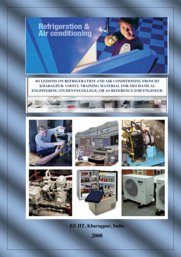
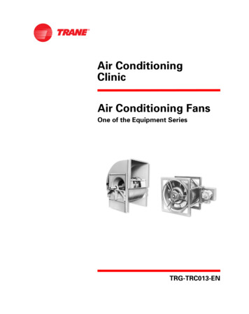
RAV Heat Pump Twin SplitsDetails are given for both RAV ’classic’ heat pumps and Digital Inverter ranges, however there are some basicprinciples that must be adhered to. Both indoor units must be of the same style, duty and serve the same room. Acommon controller will be used, individual controls is not possible.A generic arrangement is shown below:mIndoor Unit BIndoor Unit AΔhbaRrRemote ControllerHLOutdoor UnitMWhere;L Main Pipea & b Branch pipesM Main interconnecting wiringm Master to Slave power supplyR Controller interconnecting wiringr Master to Slave(s) group wiringH Overall system height differenceΔh Height difference between indoor unitsConfigurationsWhen twinning a pair of digital inverter indoor units to one outdoor the twin kit detailed below must be used.Digital InverterOutdoor Unit / Twin kitRAV ‘classic’Indoor Units x 2RAV-SM1101/2 AT-E/ *CT-ERAV-SM56*UT-ERAV-SM56*BT-ERAV-SM1401/2 AT-E/ *CT-ERAV-SM80*UT-ERAV-SM80*BT-EOutdoor Unit (twin kit 8-PERAV-464AH8-PEPage 12 of 72Indoor Units x KH-ERAV-264NH/SH/KH/CH/UH/TUH/BH-PERAV-265KH-E
RAV Heat Pump Twin SplitsThe branch lengths, where feasible, should be equal, however a slight difference is permitted. Units will be of thesame style, duty and serve the same room. A common controller will be used.Pipe SpecificationsModel (RAV-)Piping Lengths (one way)Main Pipe*Branch Pipe(L a or L b)(a or b)SizesSizesMax 50m(actual)5/8 & 3/8Max 70mSP1100/1/2/AT(actual)SP1400AT-E5/8 & 3/8Max 30mRAV-164AH-PE(actual)1/2 & 1/4Max 30mRAV-264AH-PE(actual)RAV-264AH8-PE5/8 & 3/8Max 50m(actual)RAV-364AH8-PE3/4 & 3/8(7/8 suction ifover 30m)Max 50m(actual)RAV-464AH8-PE3/4 & 3/8(7/8 suction ifover 30m)* Branch piping length is for one leg sobelow 7 or 10m as specified.SM1100/1/2/ATSM1400AT-E& SizesBranch Pipedifferentiallength (a-b orb-a)Max 15m(actual)1/2 & 1/4Max 15m(actual)5/8 & 3/8Max 5m(actual)1/2 & 1/4Max 5m(actual)1/2 & 1/4Height DifferenceOutdoor Unit – Indoor Unit (H)Indoor unitheightOutdoor UnitIndoor Unitdifference (Δh)higherhigherCommentsMax 10mMax 30mMax 15mMax 0.5mLess than 10bendsMax 10mMax 30mMax 15mMax 0.5mLess than 10bendsMax 7mMax 30mMax 15mMax 0.5mLess than 10bendsMax 7mMax 30mMax 15mMax 0.5mLess than 10bendsMax 5m(actual)1/2 & 1/4Max 7mMax 30mMax 20mMax 0.5mLess than 10bendsMax 5m(actual)5/8 & 3/8Max 7mMax 30mMax 20mMax 0.5mLess than 10bendsthe max total branch is double this figure; please observe that the length difference "a-b" or "b-a" shall beElectrical DetailsRefer to schematic diagram on previous pageM main interconnecting – powerand comsm master to slave power onlyR master to remote – low voltageand comsr master to group coms onlyDigital InverterTerminals 1 2 33 core earth (min 5 Amp rated)Terminals 1 2 only2 core earth (min 5 Amp rated)Terminals A & BRAV ‘classic’ heat pumpTerminals 1 2 33 core earth (min 5 Amp rated)Terminals 1 2 only2 core earth (min 5 Amp rated)Terminals A B & CTerminals A & BTerminals B & C onlyNote:The digital inverter systems will automatically set the internal addresses necessary.The RAV classic range needs to have the address manually set at the indoor unit PCB. Using rotary switch SW01 setthe master at 1 and the slave at 2. In addition SW05 switch, on both master and slave, needs to be set for twinoperation, put ‘bit1’ to on and ‘bit2’ to off.Additional ChargeAdditional Amount (kg) Main pipe [(L-18) x L] Branch Pipe [(a b-4) x l]ModelSizes (“)1100 / 1 / 2 AT1400 / 1 / 2 &3/83/81/43/83/83/8Main PipesPre-charge (m)181818181818Add amount(kg/m) – [ L ]0.0400.0400.0350.0350.0350.050Page 13 of 72Sizes nch pipesPre-charge (m)222222Add amount(g/m) – [ l ]0.0200.0400.0350.0350.0350.035
RBC-16DIF1-PE (16:1 Interface)One 16:1 interface allows two multi controllers to be connected to one interconnecting terminal. Four multi controllerswill require two 16:1 interfaces. This interface is purely a communication device; no refrigeration components areincluded in this kit. The indoor units are then connected, wired and piped, to the multi controllers in the normal VRFmanner.Electrical Connections(Indoor units not shown)Three Multi ControllersFour-Multi ControllersOutdoor UnitM/C 1M/C 21 2 3 Gnd1 2 3 Gnd1 2 3 Gnd16:1 Interface1 2 3 Gnd 1 2 3 GndOutdoor UnitM/C 1M/C 21 2 3 Gnd1 2 3 Gnd1 2 3 Gnd16:1 Interface1 2 3 Gnd 1 2 3 Gnd1 2 3 Gnd16:1 Interface1 2 3 Gnd 1 2 3 Gnd1 2 3 Gnd1 2 3 Gnd1 2 3 Gnd1 2 3 Gnd1 2 3 Gnd1 2 3 Gnd1 2 3 GndM/C 1M/C 2M/C 3M/C 1M/C 2M/C 3M/C 4Piping ConnectionsWhen using three or four multi controllers the piping arrangements are different to the standard one / two multicontroller installations.Three Multi ControllersFour-Multi ControllersOutdoor UnitM/C 1M/C 2Outdoor UnitM/C 3M/C 1M/C 2M/C 3M/C 4Where; Main Pipe Sizes Sub Pipe SizesPipe size specifications are detailed in the section headed “Twin and Multi-Split Refrigeration Details”.There should be a minimum 500mm of straight pipe before a T-piece, to ensure equal distribution.Please note when using this accessory the formula for calculating the additional gas charge differs from the original,see next page.Page 14 of 72
RBC-16DIF1-PE cont.Additional Gas Charge CalculationOutdoor UnitOutdoor UnitM1M2M3S1S2Main PipesS4S3Sub PipesM/C 1M/C 2M/C 1M/C 2Multi ControllersBranch PipesIndoor UnitsMAR-C104MAR-M104MAR-F104MAR-F105Main Pipes(M1 M2 M3) minus 2mMain Pipes(M1 M2 M3) minus 2mMain Pipes(M1 M2 M3) minus 2m1st Longest Sub Pipe minus 1m2nd Longest Sub Pipe minus 1m1st Longest Branch Pipe minus 2m2nd Longest Branch Pipe minus 2m3rd Longest Branch Pipe minus 2m4th Longest Branch Pipe minus 2m5th Longest Branch Pipe minus 2m6th Longest Branch Pipe minus 2m7th Longest Branch Pipe minus 2m8th Longest Branch Pipe minus 2mAdditional Gas Charge xxxxxxxxxxxxxNote 1Additional charge for branch pipesRAV-10* ; 0.030 kg/mRAV-13* ; 0.030 kg/mRAV-16* ; 0.030 kg/mRAV-26* ; 0.045 kg/mRAV-36* ; 0.045 kg/mRAV-46* ; 0.045 kg/mNote 2The kg/m quantity for the mainpipe run for the MAR-F104changes from 0.190 kg/mto 0.140 kg/m whenusing a 16:1 interface.0.140 kg/m or0.190 kg/m or0.140 kg/m 0.125 kg/m 0.125 kg/m see note 1 see note 1 see note 1 see note 1 see note 1 see note 1 see note 1 see note 1 .Factory chargeMax Total ChargeMAR-C104M8-PE9.0 kg26.6 kgMAR-M104HTM8-PE 16.0 kg36.3 kgMAR-F104/5HTM8-PE 19.0 kg36.3 kgPermissible Piping Lengths and DifferentialsMain Pipes; M2 or M3 – max 15m each; but must not exceed 10m difference in the two lengths.Sub Pipes; S1 or S2 – max 15m each; but must not exceed 10m differences in the two lengths.Sub Pipes; S3 or S4 – max 15m each; but must not exceed 10m differences in the two lengths.Branch pipes, maximum individual length is 30m; the longest minus the shortest branch pipe must not exceed 10mon any one-multi controller.Page 15 of 72
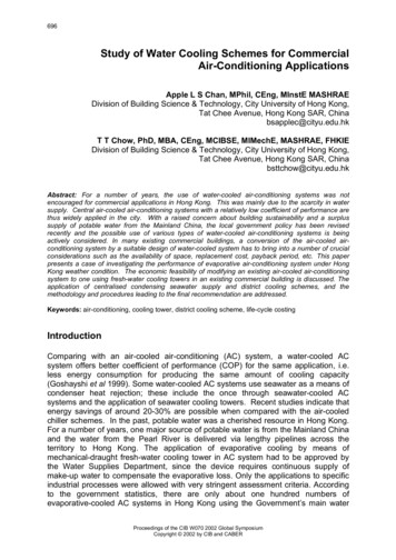
Common Circuit Boards and Switch SettingsRAV “4” Series Heat Pump Indoor UnitTypePartMCC129243A69010Air & Coil Sensor Offset ControlGroup Address Switch (Rotary)SW03 Sensor OffsetsBit TA Heating Offset2ON0ºCOFF 2ºCON 4ºCOFF 8ºCOFFNot UsedSW01 RotaryPosition 1 Group MasterPosition 2Slave 1Position 3Slave 2Position 4Slave 3Position 5Slave 4etc max 16 unitsBit1ONONOFFOFFBit3ONONOFFOFFTwin & Auto Function Enable/DisableSW05Zone Address Switch (Local Area Network, ONONONONONONONOff if using rem com to zone addressOn when using SW02 to zone addressSW02 L.A.N. Address SwitchBit3 Bit4 Bit5 Bit6 Bit7Only used with CR64 controllerNormal setting both to OFFBit 2Bit1Zone 1Zone 2Zone 3Zone 4Zone 5Zone 6Zone 7Zone 8Zone 9Zone 10Zone 11Zone 12Zone 13Zone 14Zone 15Zone 16Bit1OFFONBit2OFFONSingle Split OperationTwin Split OperationAuto Mode EnabledAuto Mode DisabledNote;Details in bold are the Factory settingsPage 16 of 72
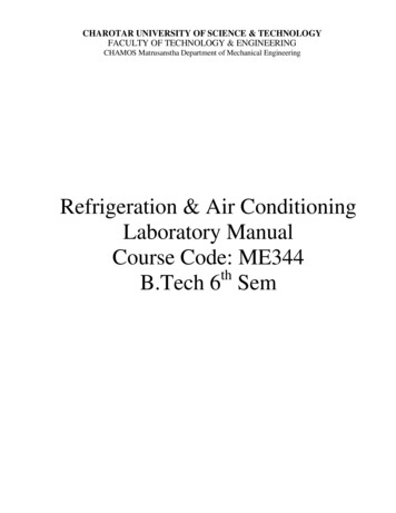
Common Circuit Boards and Switch SettingsRAV “2 & 3” Series Heat Pump Indoor UnitTypePartMCC127743A69002Group Address Switch (Rotary)Air & Coil Sensor Offset ControlSW03 Sensor OffsetsBitBit TA Heating Offset12ONON0ºCON OFF 2ºCOFF ON 4ºCOFF OFF 6ºCBitBit34TripResetON ON54ºC52ºCON OFF58ºC56ºCOFF ON60ºC58ºCOFF OFFNot UsedSW01 RotaryPosition 1 Group MasterPosition 2Slave 1Position 3Slave 2Position 4Slave 3Position 5Slave 4etc max 16 unitsRAV “2,3 & 4” Series Cooling Only Indoor UnitTypePartMCC127743A69005Group Address Switch (Rotary)SW01 RotaryPosition 1 Group MasterPosition 2Slave 1Position 3Slave 2Position 4Slave 3Position 5Slave 4etc max 16 unitsNote; Both the above circuit boards have the same typenumber and visually are very similar. They are not interchangeable; the obvious differences are marked in blue onthe lower picture.Page 17 of 72
Common Circuit Boards and Switch SettingsRAV “2,3 & 4” Series Heat Pump Outdoor UnitTypePartMCC127543A69006 ; 2 & 3 series43A69011 : 4 seriesEmergency Operation from Outdoor unitIt is possible to operate the a/c system from the outdoor unit by using the dip switches detailed above.1.Set Switch SW01 to required position.ON12Cooling Mode2.3.4.12Heating ModeApply a short across pins CN28 and CN29 until the middle yellow, D08, illuminates, then remove the short.The LED will then extinguish and the indoor units will start, after a couple of minutes the outdoor unit willthen start, LEDs D07 (yellow) and D10 (red) will light.To stop the emergency operation, re-apply the short between CCN28 and CN29. LEDs D08 and D10 willextinguish and the a/c system will stop operating.Reset SW01 to factory settings for normal operation.Page 18 of 72
Common Circuit Boards and Switch SettingsRAV “2,3 & 4” Series Heat Pump Outdoor UnitTypePartMCC127543A69006 ; 2 & 3 series43A69011 : 4 seriesInformation given by LEDsDIP PositionON1OND10 ä D09 ä 1*CompressorDemandON1CompressorActualON1LEDD08 ááá InformationD07 ä ááá Normal OperationTimer Short21, High Pressure Trip18,19, Sensor FailureNormal OperationN Failures – FirstN failures – SecondN Failures – ThirdN Failures – Fourth18,19 Sensor Failure21, High Pressure TripCompressor StopSpeed 3Speed 4Speed 5Speed 6Speed 7Speed 8Speed 9Speed 10Speed 11Speed 12Speed 13Speed 14Speed 15* Note; The compressor speed is fixed on the RAV series. á ä OffLitFlashing at 1hzFlashing at 5hzPage 19 of 72
TOSHIBA Circuit BoardsBy Type NumberTYPE No. MODEL No.PART No.COMMENTSMCC 1070 RAV-160, 260, 360, 460BH431 69 544MCC 1070 RAV-453, 713KHE(8)431 69 463MCC 1070 RAV-453, 713, 1003, 1253UHE(8) 431 69 463ET 420RAV-1800UDHE8431 50 101MCC 1070 RAV-1003, 1253FHE8431 69 463MCC 1070 RAV-453, 713LHE(8)431 69 463MCC 1070 RAV-160, 200, 260KH431 69 544431 69 469Control PCB431 69 469Control PCB430 69 878MCC 1074 RAV-S453, 713, 1003,1253HE/HE8MCC 1074 RAV-160, 200, 260, 360,460AH(8)MCC 1075 RAV-360, 460AH8431 69 467Relay PCB431 69 281MCC 1075 RAV-S1003, 1253HE8431 69 467Relay PCB431 69 327MCC 1076 RBC-TK45E431 69 502Japanese431 69 311MCC 1080 RAS-45BKHV430 69 617431 69 282MCC 1200 RAV-160, 260, 360, 460UH-P431 69 578MCC 1200 RAV-161, 261, 361, 461CH-P431 69 578H92C- RAV-G1253HE8-E11(CorGZ)431 51 210H92C- RAV-G1003HE811(CorGZ)431 51 210H92C- RAV-640AH8A11(CorGZ)431 51 210MCC 26 RAS-30PKHEMCC 35 RAV-450, 710, 1000,1250UHJE/UHE8MCC 35 RAV-451, 561
AIR CONDITIONING TECHNICAL HANDBOOK A Selection of Useful Information For Single/Twin Split, Super Multi, Modular Multi Super Modular Multi, Mini SMMS, Super Heat Recovery, Digital Inverter Models and Super Digital Inverter. 24 Hour Technical Helpline: 0870 843 0333 Ver. 11.5 TOSHIBA.