Transcription
AGRAPHICAL SYMBOLSFOR PIPING SYSTEMSAND PLANTBASED ON BS 1553: PART 1: 1977ScopeThis part of BS 1553 specifies graphical symbols for use in flow and piping diagramsfor process plant.A- 1
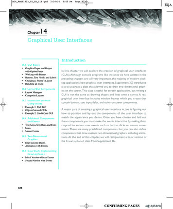
A-2APPENDIX A GRAPHICAL SYMBOLS FOR PIPING SYSTEMS AND PLANTSymbols (or elements of Symbols) for Use in Conjunction withOther SymbolsMechanical linkageWeight deviceElectrical deviceAccess pointEquipment branch:general symbolNote. The upper representation does notnecessarily imply aflange, merely the termination point. Where abreakable connection isrequired the branch/pipewould be as shown in thelower symbolVibratory or loadingdevice (any type)Equipment penetration(fixed)Spray deviceEquipment penetration(removable)Rotary movementBoundary lineStirring devicePoint of changeFanDischarge to atmosphere
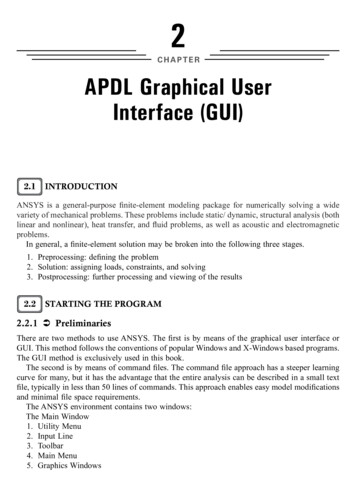
APPENDIX A GRAPHICAL SYMBOLS FOR PIPING SYSTEMS AND PLANTBasic and Developed Symbols for Plant and EquipmentHeat Transfer EquipmentHeat exchanger (basic symbols)Alternative:Shell and tube: fixed tube sheetShell and tube: U tube or floating headShell and tube: kettle reboilerAir-blown coolerPlate typeDouble pipe typeHeating / cooling coil (basic symbol)Fired heater / boiler (basic symbol)A- 3
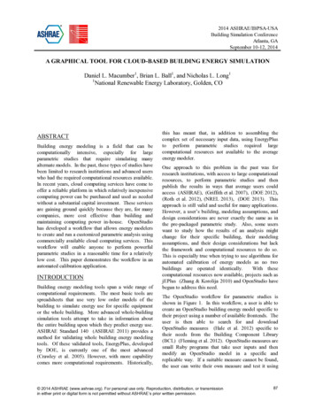
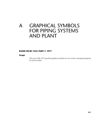
A- 4APPENDIX A GRAPHICAL SYMBOLS FOR PIPING SYSTEMS AND PLANTUpshot heaterDetail AWhere complex burners are employedthe ‘‘burner block’’ may be detailedelsewhere on the drawing, thusDetail AVessels and TanksDrum or simple pressure vessel(basic symbol)Knock-out drum (with demister pad)Tray column (basic symbol)Tray columnTrays should be numbered from thebottom; at least the first and the lastshould be shown. Intermediate traysshould be included and numbered wherethey are significant.3014
APPENDIX A GRAPHICAL SYMBOLS FOR PIPING SYSTEMS AND PLANTFluid contacting vessel (basic symbol)Fluid contacting vesselSupport grids and distribution detailsmay be shownReaction or absorption vessel(basic symbol)Reaction or absorption vesselWhere it is necessary to show more thanone layer of material alternativehatching should be usedAutoclave (basic symbol)AutoclaveA- 5
A- 6APPENDIX A GRAPHICAL SYMBOLS FOR PIPING SYSTEMS AND PLANTOpen tank (basic symbol)Open tankClarifier or settling tankSealed tankCovered tankTank with fixed roof (with draw-offsump)Tank with floating roof (with roof drain)Storage sphereGas holder (basic symbol for all types)
APPENDIX A GRAPHICAL SYMBOLS FOR PIPING SYSTEMS AND PLANTPumps and CompressorsRotary pump, fan or simple compressor(basic symbol)Centrifugal pump or centrifugal fanCentrifugal pump (submerged suction)Positive displacement rotary pump or rotarycompressorPositive displacement pump (reciprocating)Axial flow fanCompressor: centrifugal/axial flow (basicsymbol)Compressor: centrifugal/axial flowCompressor: reciprocating (basic symbol)Ejector/injector (basic symbol)A- 7
A- 8APPENDIX A GRAPHICAL SYMBOLS FOR PIPING SYSTEMS AND PLANTSolids HandlingSize reductionBreaker gyratoryRoll crusherPulverizer : ball millMixing (basic symbol)KneaderRibbon blenderDouble cone blenderFilter (basic symbol, simple batch)Filter press (basic symbol)Rotary filter, film drier or flaker
APPENDIX A GRAPHICAL SYMBOLS FOR PIPING SYSTEMS AND PLANTCyclone and hydroclone (basic symbol)Cyclone and hydrocloneCentrifuge (basic symbol)Centrifuge: horizontal peeler typeCentrifuge: disc bowl typeDryingDrying ovenBelt drier (basic symbol)Rotary drier (basic symbol)Rotary kilnA- 9
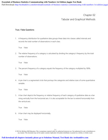
A- 10APPENDIX A GRAPHICAL SYMBOLS FOR PIPING SYSTEMS AND PLANTSpray drierBelt conveyorScrew conveyorElevator (basic symbol)Electric motor (basicsymbol)Turbine (basic symbol)
APPENDIX A GRAPHICAL SYMBOLS FOR PIPING SYSTEMS AND PLANT A- 3. Upshot heater Where complex burners are employed the ‘‘burner block’’ may be detailed elsewhere on the drawing, thus Detail A Detail A Vessels and Tanks Drum or simple pressure vessel (basic symbol) Knock-out drum (with demister pad) Tray column (basic symbol) Tray column Trays should be numbered from the bottom;