Transcription
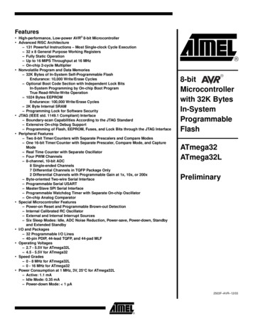
Features High-performance, Low-power AVR 8-bit Microcontroller Advanced RISC Architecture – 131 Powerful Instructions – Most Single-clock Cycle Execution– 32 x 8 General Purpose Working Registers– Fully Static Operation– Up to 16 MIPS Throughput at 16 MHz– On-chip 2-cycle MultiplierNonvolatile Program and Data Memories– 32K Bytes of In-System Self-Programmable FlashEndurance: 10,000 Write/Erase Cycles– Optional Boot Code Section with Independent Lock BitsIn-System Programming by On-chip Boot ProgramTrue Read-While-Write Operation– 1024 Bytes EEPROMEndurance: 100,000 Write/Erase Cycles– 2K Byte Internal SRAM– Programming Lock for Software SecurityJTAG (IEEE std. 1149.1 Compliant) Interface– Boundary-scan Capabilities According to the JTAG Standard– Extensive On-chip Debug Support– Programming of Flash, EEPROM, Fuses, and Lock Bits through the JTAG InterfacePeripheral Features– Two 8-bit Timer/Counters with Separate Prescalers and Compare Modes– One 16-bit Timer/Counter with Separate Prescaler, Compare Mode, and CaptureMode– Real Time Counter with Separate Oscillator– Four PWM Channels– 8-channel, 10-bit ADC8 Single-ended Channels7 Differential Channels in TQFP Package Only2 Differential Channels with Programmable Gain at 1x, 10x, or 200x– Byte-oriented Two-wire Serial Interface– Programmable Serial USART– Master/Slave SPI Serial Interface– Programmable Watchdog Timer with Separate On-chip Oscillator– On-chip Analog ComparatorSpecial Microcontroller Features– Power-on Reset and Programmable Brown-out Detection– Internal Calibrated RC Oscillator– External and Internal Interrupt Sources– Six Sleep Modes: Idle, ADC Noise Reduction, Power-save, Power-down, Standbyand Extended StandbyI/O and Packages– 32 Programmable I/O Lines– 40-pin PDIP, 44-lead TQFP, and 44-pad MLFOperating Voltages– 2.7 - 5.5V for ATmega32L– 4.5 - 5.5V for ATmega32Speed Grades– 0 - 8 MHz for ATmega32L– 0 - 16 MHz for ATmega32Power Consumption at 1 MHz, 3V, 25 C for ATmega32L– Active: 1.1 mA– Idle Mode: 0.35 mA– Power-down Mode: 1 µA8-bitMicrocontrollerwith 32K eliminary2503F–AVR–12/03
Pin ConfigurationsFigure 1. Pinouts ATmega32PDIP(XCK/T0) PB0(T1) PB1(INT2/AIN0) PB2(OC0/AIN1) PB3(SS) PB4(MOSI) PB5(MISO) PB6(SCK) PB7RESETVCCGNDXTAL2XTAL1(RXD) PD0(TXD) PD1(INT0) PD2(INT1) PD3(OC1B) PD4(OC1A) PD5(ICP) PD6PA0 (ADC0)PA1 (ADC1)PA2 (ADC2)PA3 (ADC3)PA4 (ADC4)PA5 (ADC5)PA6 (ADC6)PA7 (ADC7)AREFGNDAVCCPC7 (TOSC2)PC6 (TOSC1)PC5 (TDI)PC4 (TDO)PC3 (TMS)PC2 (TCK)PC1 (SDA)PC0 (SCL)PD7 (OC2)PB4 (SS)PB3 (AIN1/OC0)PB2 (AIN0/INT2)PB1 (T1)PB0 (XCK/T0)GNDVCCPA0 (ADC0)PA1 (ADC1)PA2 (ADC2)PA3 (ADC3)TQFP/MLF(MOSI) PB5(MISO) PB6(SCK) PB7RESETVCCGNDXTAL2XTAL1(RXD) PD0(TXD) PD1(INT0) ND(SCL) PC0(SDA) PC1(TCK) PC2(TMS) PC3PA4 (ADC4)PA5 (ADC5)PA6 (ADC6)PA7 (ADC7)AREFGNDAVCCPC7 (TOSC2)PC6 (TOSC1)PC5 (TDI)PC4 (TDO)Disclaimer2Typical values contained in this datasheet are based on simulations and characterization of other AVR microcontrollers manufactured on the same process technology. Minand Max values will be available after the device is characterized.ATmega32(L)2503F–AVR–12/03
ATmega32(L)OverviewThe ATmega32 is a low-power CMOS 8-bit microcontroller based on the AVR enhancedRISC architecture. By executing powerful instructions in a single clock cycle, theATmega32 achieves throughputs approaching 1 MIPS per MHz allowing the systemdesigner to optimize power consumption versus processing speed.Block DiagramFigure 2. Block DiagramPA0 - PA7PC0 - PC7PORTA DRIVERS/BUFFERSPORTC DRIVERS/BUFFERSPORTA DIGITAL INTERFACEPORTC DIGITAL INTERFACEVCCGNDAVCCMUX ERYMCU CTRL.& TIMINGRESETZCONTROLLINESALUINTERRUPTUNITAVR CPUSTATUSREGISTEREEPROMPROGRAMMINGLOGICSPIUSART -INTERNALCALIBRATEDOSCILLATORCOMP.INTERFACEPORTB DIGITAL INTERFACEPORTD DIGITAL INTERFACEPORTB DRIVERS/BUFFERSPORTD DRIVERS/BUFFERSPB0 - PB7PD0 - PD732503F–AVR–12/03
The AVR core combines a rich instruction set with 32 general purpose working registers.All the 32 registers are directly connected to the Arithmetic Logic Unit (ALU), allowingtwo independent registers to be accessed in one single instruction executed in one clockcycle. The resulting architecture is more code efficient while achieving throughputs up toten times faster than conventional CISC microcontrollers.The ATmega32 provides the following features: 32K bytes of In-System ProgrammableFlash Program memory with Read-While-Write capabilities, 1024 bytes EEPROM, 2Kbyte SRAM, 32 general purpose I/O lines, 32 general purpose working registers, aJTAG interface for Boundary-scan, On-chip Debugging support and programming, threeflexible Timer/Counters with compare modes, Internal and External Interrupts, a serialprogrammable USART, a byte oriented Two-wire Serial Interface, an 8-channel, 10-bitADC with optional differential input stage with programmable gain (TQFP package only),a programmable Watchdog Timer with Internal Oscillator, an SPI serial port, and sixsoftware selectable power saving modes. The Idle mode stops the CPU while allowingthe USART, Two-wire interface, A/D Converter, SRAM, Timer/Counters, SPI port, andinterrupt system to continue functioning. The Power-down mode saves the register contents but freezes the Oscillator, disabling all other chip functions until the next ExternalInterrupt or Hardware Reset. In Power-save mode, the Asynchronous Timer continuesto run, allowing the user to maintain a timer base while the rest of the device is sleeping.The ADC Noise Reduction mode stops the CPU and all I/O modules except Asynchronous Timer and ADC, to minimize switching noise during ADC conversions. In Standbymode, the crystal/resonator Oscillator is running while the rest of the device is sleeping.This allows very fast start-up combined with low-power consumption. In ExtendedStandby mode, both the main Oscillator and the Asynchronous Timer continue to run.The device is manufactured using Atmel’s high density nonvolatile memory technology.The On-chip ISP Flash allows the program memory to be reprogrammed in-systemthrough an SPI serial interface, by a conventional nonvolatile memory programmer, orby an On-chip Boot program running on the AVR core. The boot program can use anyinterface to download the application program in the Application Flash memory. Software in the Boot Flash section will continue to run while the Application Flash section isupdated, providing true Read-While-Write operation. By combining an 8-bit RISC CPUwith In-System Self-Programmable Flash on a monolithic chip, the Atmel ATmega32 isa powerful microcontroller that provides a highly-flexible and cost-effective solution tomany embedded control applications.The ATmega32 AVR is supported with a full suite of program and system developmenttools including: C compilers, macro assemblers, program debugger/simulators, in-circuitemulators, and evaluation kits.Pin DescriptionsVCCDigital supply voltage.GNDGround.Port A (PA7.PA0)Port A serves as the analog inputs to the A/D Converter.Port A also serves as an 8-bit bi-directional I/O port, if the A/D Converter is not used.Port pins can provide internal pull-up resistors (selected for each bit). The Port A outputbuffers have symmetrical drive characteristics with both high sink and source capability.When pins PA0 to PA7 are used as inputs and are externally pulled low, they will sourcecurrent if the internal pull-up resistors are activated. The Port A pins are tri-stated whena reset condition becomes active, even if the clock is not running.4ATmega32(L)2503F–AVR–12/03
ATmega32(L)Port B (PB7.PB0)Port B is an 8-bit bi-directional I/O port with internal pull-up resistors (selected for eachbit). The Port B output buffers have symmetrical drive characteristics with both high sinkand source capability. As inputs, Port B pins that are externally pulled low will sourcecurrent if the pull-up resistors are activated. The Port B pins are tri-stated when a resetcondition becomes active, even if the clock is not running.Port B also serves the functions of various special features of the ATmega32 as listedon page 55.Port C (PC7.PC0)Port C is an 8-bit bi-directional I/O port with internal pull-up resistors (selected for eachbit). The Port C output buffers have symmetrical drive characteristics with both high sinkand source capability. As inputs, Port C pins that are externally pulled low will sourcecurrent if the pull-up resistors are activated. The Port C pins are tri-stated when a resetcondition becomes active, even if the clock is not running. If the JTAG interface isenabled, the pull-up resistors on pins PC5(TDI), PC3(TMS) and PC2(TCK) will be activated even if a reset occurs.The TD0 pin is tri-stated unless TAP states that shift out data are entered.Port C also serves the functions of the JTAG interface and other special features of theATmega32 as listed on page 58.Port D (PD7.PD0)Port D is an 8-bit bi-directional I/O port with internal pull-up resistors (selected for eachbit). The Port D output buffers have symmetrical drive characteristics with both high sinkand source capability. As inputs, Port D pins that are externally pulled low will sourcecurrent if the pull-up resistors are activated. The Port D pins are tri-stated when a resetcondition becomes active, even if the clock is not running.Port D also serves the functions of various special features of the ATmega32 as listedon page 60.RESETReset Input. A low level on this pin for longer than the minimum pulse length will generate a reset, even if the clock is not running. The minimum pulse length is given in Table15 on page 35. Shorter pulses are not guaranteed to generate a reset.XTAL1Input to the inverting Oscillator amplifier and input to the internal clock operating circuit.XTAL2Output from the inverting Oscillator amplifier.AVCCAVCC is the supply voltage pin for Port A and the A/D Converter. It should be externallyconnected to VCC, even if the ADC is not used. If the ADC is used, it should be connected to VCC through a low-pass filter.AREFAREF is the analog reference pin for the A/D Converter.About CodeExamplesThis documentation contains simple code examples that briefly show how to use variousparts of the device. These code examples assume that the part specific header file isincluded before compilation. Be aware that not all C Compiler vendors include bit definitions in the header files and interrupt handling in C is compiler dependent. Pleaseconfirm with the C Compiler documentation for more details.52503F–AVR–12/03
AVR CPU CoreIntroductionThis section discusses the AVR core architecture in general. The main function of theCPU core is to ensure correct program execution. The CPU must therefore be able toaccess memories, perform calculations, control peripherals, and handle interrupts.Architectural OverviewFigure 3. Block Diagram of the AVR MCU ArchitectureData Bus 8-bitFlashProgramMemoryProgramCounterStatusand Control32 x 8GeneralPurposeRegistrersControl LinesDirect AddressingInstructionDecoderIndirect atchdogTimerALUAnalogComparatorI/O Module1DataSRAMI/O Module 2I/O Module nEEPROMI/O LinesIn order to maximize performance and parallelism, the AVR uses a Harvard architecture– with separate memories and buses for program and data. Instructions in the programmemory are executed with a single level pipelining. While one instruction is being executed, the next instruction is pre-fetched from the program memory. This conceptenables instructions to be executed in every clock cycle. The program memory is InSystem Reprogrammable Flash memory.The fast-access Register File contains 32 x 8-bit general purpose working registers witha single clock cycle access time. This allows single-cycle Arithmetic Logic Unit (ALU)operation. In a typical ALU operation, two operands are output from the Register File,the operation is executed, and the result is stored back in the Register File – in oneclock cycle.Six of the 32 registers can be used as three 16-bit indirect address register pointers forData Space addressing – enabling efficient address calculations. One of the theseaddress pointers can also be used as an address pointer for look up tables in Flash Program memory. These added function registers are the 16-bit X-, Y-, and Z-register,described later in this section.The ALU supports arithmetic and logic operations between registers or between a constant and a register. Single register operations can also be executed in the ALU. After6ATmega32(L)2503F–AVR–12/03
ATmega32(L)an arithmetic operation, the Status Register is updated to reflect information about theresult of the operation.Program flow is provided by conditional and unconditional jump and call instructions,able to directly address the whole address space. Most AVR instructions have a single16-bit word format. Every program memory address contains a 16- or 32-bit instruction.Program Flash memory space is divided in two sections, the Boot program section andthe Application Program section. Both sections have dedicated Lock bits for write andread/write protection. The SPM instruction that writes into the Application Flash memorysection must reside in the Boot Program section.During interrupts and subroutine calls, the return address Program Counter (PC) isstored on the Stack. The Stack is effectively allocated in the general data SRAM, andconsequently the Stack size is only limited by the total SRAM size and the usage of theSRAM. All user programs must initialize the SP in the reset routine (before subroutinesor interrupts are executed). The Stack Pointer SP is read/write accessible in the I/Ospace. The data SRAM can easily be accessed through the five different addressingmodes supported in the AVR a
ATmega32(L) 2503F–AVR–12/03 Overview The ATmega32 is a low-power CMOS 8-bit microcontroller based on the AVR enhanced RISC architecture. By executing powerful instructions in a single clock cycle, the ATmega32 achieves throughputs approaching 1 MIPS per MHz allowing the system designer to optimize power consumption versus processing speed.