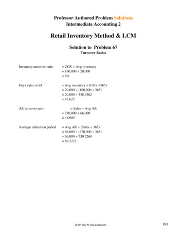
Transcription
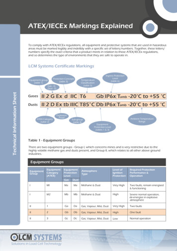
ATEX/IECEx Markings ExplainedTo comply with ATEX/IECEx regulations, all equipment and protective systems that are used in hazardousareas must be marked legibly and indelibly with a specific set of letters/numbers. Together, these letters/numbers specify the exact criteria that a product meets in relation to those ATEX/IECEx regulations,and so determines the type of environments that they are safe to operate in.LCM Systems Certificate MarkingsTechnical Information SheetProtection ConceptsEquipment group(table 3)(table 1)Gas - GDust - DIngress ProtectionLevel(table 6)TemperatureClassification(table 5)GasesII 2 G Ex d IIC T6DustsII 2 D Ex tb IIIC T85 C Db IP6x Tamb -20 C to 55 CATEX Category(table 2)ExplosionProofSub-group(table 4)Gb IP6x Tamb -20 C to 55 CAmbient TemperatureRangeEquipmentProtection Level(tables 1 & 3)Table 1 - Equipment GroupsThere are two equipment groups - Group I, which concerns mines and is very restrictive due to thehighly volatile methane gas and dusts present, and Group II, which relates to all other above groundindustries.Equipment ntProtectionLevelGasDustAtmosphereTypeLevel ofIgnitionProtectionRequired ProtectionPerformance &OperationIMIMaMaMethane & DustVery HighTwo faults, remain energised& functioningIM2MbMbMethane & DustHighSevere normal operation,de-energise in explosiveatmosphereII1GaDaGas, Vapour, Mist, DustVery HighTwo faultsII2GbDbGas, Vapour, Mist, DustHighOne faultII3GcDcGas, Vapour, Mist, DustLowNormal operationLCM SYSTEMSSolutions in Load Cell Technology
ATEX/IECEx Markings ExplainedTable 2 - ATEX CategoryThere are three area category types, with Category 1 requiring a very high level of protection and definedas an area having a permanent or prolonged risk of explosions (Zone 0), Category 2 which requires a highlevel of protection and has a frequent risk of an explosive mix being present in the air (Zone 1), andCategory 3, specified as requiring a normal level of protection with a small chance of an explosive mixforming (Zone 2).Area ClassificationEquipment CategoryZoneDefinitionGases &VapoursDustsCategory 1An area where an explosive atmosphere ispresent continuously or for long periods(over 1000 hours per year or 10% of the time)Zone 0Zone 20Category 2An area where an explosive atmosphere islikely to occur in normal operation(10 - 1000 hours per year or 0.1 to 10% of the time)Zone 1Zone 21Category 3An area where an explosive atmosphere is notlikely to occur in normal operation(under 10 hours per year or 0 to 0.1% of the time)Zone 2Zone 22Note: Category 2 certification also covers the lower category 3Table 3 - Protection ConceptsProtection concepts refer to the means of ensuring a piece of equipment being used in a hazardous areadoes not cause an explosion. There are four basic methods utilised to avoid uncontrolled ignitions exclusion of the flammable substance, prevention of component sparks or hot surfaces, explosionquenching and energy limitation. By applying individually or in combination, the protection concepts listedbelow are applied to a product in order to achieve this.SymbolEquipment Indicative ZonesProtectionLevelStandard(EN/IEC)Basic Concept of ProtectionOptical radiationOp prOp shOP isGbGaGa1, 20, 1, 20, 1, 260079-2860079-2860029-78Protected by shutdown, enclosureor inherently safeIncreased safetytype ‘n’ (nonsparking)enAGbGc1, 2260079-760079-15No sparking parts or hot surfacesFlameproofdGb1, 260079-1Type ‘n’ (enclosed nCbreak)Gc260079-15Contains the pressure, quench theflameContains the pressure, quench theflameQuartz/Sand filledGb1, 260079-5Type ofProtectionqLCM SYSTEMSSolutions in Load Cell TechnologyQuench ignitionTechnical Information SheetProtection Concepts - Electrical Equipment for gases, vapours & mists (G)
ATEX/IECEx Markings ExplainedTable 3 - Protection Concepts (continued)SymbolEquipment Indicative ZonesProtectionLevelStandard(EN/IEC)iaibicGaGbGc0, 1, 21, 2260079-11Limit the potential ignition energyand surface temperaturespxpypzGbGbGc1, 21, 2260079-2Keeps the flammable gas outType ‘n’ (sealing & nChermetic sealing) nRType ‘n’ mbmcGaGbGc0, 1, 21, 2260079-18Oil immersionoGb1, 260079-6Type ofProtectionIntrinsic safetyPressurisedBasic Concept of ProtectionProtection Concepts - Electrical Equipment for dusts (D)Type ofProtectionSymbolEquipmentProtection Indicative 12260079-31Dust tight enclosure, limited surfacetemperatureIntrinsic safetyiaibicDaDbDc20212260079-11Limit the potential ignition energyand surface temperatures. May addingress 8Keep the flammable dust outPressurisedpDDbDc212260079-4Protection by pressurisation ofenclosureBasic Concept of ProtectionLCM SYSTEMSSolutions in Load Cell TechnologyTechnical Information SheetNote: tb (Zone 21) certification also covers the lower tc classification (Zone 22)
ATEX/IECEx Markings ExplainedTable 4 - Gas Sub-divisionsThe ATEX standard also has a classification for explosive gases and dusts, with Group I referring tomethane gases and coal dust (mining), while Group IIA to IIC gases and Group IIIA and IIIC dusts (aboveground industries) have been categorised according to their different igniting power, with IIA/IIIA beingthe least dangerous and having the highest ignition temperature and IIC/IIIC the most dangerous with thelowest ignition temperature.Group Sub DivisionsGas Sub GroupsRepresentative GasDust Sub GroupsDust TypeGroup 1MethaneGroup 1Coal DustGroup IIAPropaneGroup IIIAFlyingsGroup IIBEthyleneGroup IIIBNon-conductiveGroup IICHydrogen/AcetyleneGroup IIICConductiveNote: Group IIC/Group IIIC certification is the highest possible, so also covers the groups aboveTable 5 - Temperature ClassificationDifferent substances may combust at different temperatures. The lower the combustion temperature is, themore dangerous the substance is. Therefore, each piece of equipment used in an explosive environment isclassified according to the maximum surface temperature it generates. The maximum surface temperatureof the equipment should always be well below the ignition temperature of the gases present.Temperature classMax Surface Temperature ofEquipment CIgnition Temperaturesof Flammable Substance CT1450 450T2300 300 450280 280 300260 260 280230 230 260215 215 230200 200 215180 180 200165 165 180160 160 165135 135 160120 120 135T5100 100 120T685 85 100T3T4Note: Temperature class 85 C certification is the highest possible, so also covers the classes aboveLCM SYSTEMSSolutions in Load Cell TechnologyTechnical Information SheetTemperature Classification
ATEX/IECEx Markings ExplainedTable 6 - Ingress ProtectionThis rating system (or IP code) is defined by the letters IP followed by two 'characteristic' numbers. The firstnumber identifies the degree of protection against solid foreign objects and the second number refers toits protection against liquids.LevelProtected AgainstSolid Particle Ingress Protection (First Digit of Code)0-No protection against contact and ingress of objects1 50 mmAny large surface of the body, such as the back of a hand, but no protectionagainst deliberate contact with a body part2 12.5 mmFingers or similar objects3 2.5 mmTools, thick wires etc.4 1mmMost wires, screws etc.5Dust protected6Dust tightIngress of dust is not entirely prevented, but it must not enter in sufficientquantity to interfere with the safe operation of the equipment; completeprotection against contactNo ingress of dust; complete protection against contactLevelProtected AgainstLiquid Ingress Protection (Second Digit of Code)0Not protectedNot necessary1Dripping waterDripping water (vertically falling drops) shall have no harmful effect2Dripping waterwhen tilted up to 15 CVertically dripping water shall have no harmful effect when the enclosure istilted at an angle up to 15 C from its normal position3Spraying waterWater falling as a vertical spray at any angle up to 60 C from the vertical shallhave no harmful effect4Splashing waterWater splashing against the enclosure from any direction shall have no harmfuleffect5Water jetsWater projected by a nozzle (6.3mm) against enclosure from any direction shallhave no harmful effects6Powerful water jetsWater projected in powerful jets (12.5mm nozzle) against the enclosure fromany direction shall have no harmful effects7Immersion up to 1 mtrIngress of water in harmful quantity shall not be possible when the enclosure isimmersed in water under defined conditions of pressure and time (up to 1metre of submersion)8Immersion beyond 1mtrThe equipment is suitable for continuous immersion in water under conditionwhich shall be specified by the manufacturerTechnical Information SheetIngress ProtectionNote: IP67 is the standard protection offered by LCM System, however, lower and higher protection is availableLCM Systems LtdUnit 15, Newport Business ParkBarry Way, NewportIsle of Wight PO30 5GY UKLCM SYSTEMSSolutions in Load Cell TechnologyTel: 44 (0)1983 249264Fax: 44 (0)1983 249266sales@lcmsystems.comwww.atexloadcell.com
Table 2 - ATEX Category There are three area category types, with Category 1 requiring a very high level of protection and defined as an area having a permanent or prolonged risk of explosions (Zone 0), Category 2 which requires a high level of protection and has a frequent risk of an explosive mix being present in the air (Zone 1), and