Transcription
1300 2.5-Inch and M.2 NAND Flash SSDFeatures1300 2.5-Inch and M.2 SATA NAND FlashSSDMTFDDAK256TDL, MTFDDAK512TDL, MTFDDAK1T0TDL,MTFDDAK2T0TDL, MTFDDAV256TDL, MTFDDAV512TDL,MTFDDAV1T0TDLFeatures Reliability– MTTF: 1.5 million device hours3– Static and dynamic wear leveling– Uncorrectable bit error rate (UBER): 1 sectorper 1015 bits read Low power consumption– Device sleep numbers: 10mW– DIPM numbers: 55mW TYP 4 Endurance: Total bytes written (TBW)– Up to 400TB Capacity5 (unformatted): 256GB, 512GB, 1024GB,2048GB Mechanical– 2.5-inch 7mm form factor– M.2 Type 2280 form factor Secure firmware update with digitally signed firmware image Operating temperature– Commercial (0 C to 70 C)6Micron 3D TLC NAND FlashRoHS-compliant packageSATA 6 Gb/s interfaceTCG/Opal 2.0-compliant self-encrypting drive(SED)Compatible with Microsoft eDrive Hardware-based AES-256 encryption engineATA modes supported– PIO mode 3, 4– Multiword DMA mode 0, 1, 2– Ultra DMA mode 0, 1, 2, 3, 4, 5, 6Industry-standard, 512-byte sector size supportHot-plug/hot-remove capable (2.5")Device sleep (DEVSLP), extreme low-power modeNative command queuing support with 32-command slot supportATA-8 ACS4 command set compliantATA security feature command set and passwordlogin supportSecure erase (data page) command set: fast and secure eraseSanitize device feature set supportSelf-monitoring, analysis, and reporting technology(SMART) command setDynamic write accelerationAdaptive thermal monitoringPower loss protection for data-at-restPerformance1, 2– PCMark Vantage (HDD test suite score): Up to84,000– Sequential 128KB READ: Up to 530 MB/s– Sequential 128KB WRITE: Up to 520 MB/s– Random 4KB READ: Up to 90,000 IOPS– Random 4KB WRITE: Up to 87,000 IOPS– READ/WRITE latency: 85µs/40µs (TYP)CCM005-731836775-105321300 ssd.pdf - Rev. A 9/18 ENNotes:1. Typical I/O performance numbers as measured fresh-out-of-the-box (FOB) with aqueue depth of 32 and write cache enabled.2. 4KB transfers QD 1 used for READ/WRITElatency values.3. The product achieves a mean time to failure(MTTF) based on population statistics notrelevant to individual units.4. Active average power measured during execution of MobileMark with DIPM (deviceinitiated power management) enabled.5. 1GB 1,000,000,000 bytes6. As reported by SMART.Warranty: Contact your Micron sales representativefor further information regarding the product,including product warranties.1Micron Technology, Inc. reserves the right to change products or specifications without notice. 2018 Micron Technology, Inc. All rights reserved.Products and specifications discussed herein are subject to change by Micron without notice.
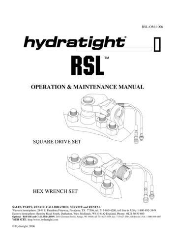
1300 2.5-Inch and M.2 NAND Flash SSDFeaturesPart Numbering InformationMicron’s 1300 SSD is available in different configurations and densities. The chart below is a comprehensive list ofoptions for the 1300 series devices; not all options listed can be combined to define an offered product. Visitwww.micron.com for a list of valid part numbers.Figure 1: Part Number ChartMT FDDAK 256 TDL- 1AW 12AB YY ESProduction StatusMicron TechnologyBlank ProductionES Engineering sampleProduct FamilyFD Flash driveCustomer DesignatorDrive InterfaceYY StandardD SATA 6.0 Gb/sFeature SetDrive Form FactorAK 2.5-inch (7mm)AV M.2 (80mm x 22mm)AB StandardTA TAA CompliantZZ BlankDrive DensityExtended Firmware Features256 256GB512 512GB1T0 1024GB2T0 2048GB1 512 byteNAND Flash TypeNAND Flash ComponentZ Non-Encrypted2 SED (self-encrypting drive)Sector SizeT TLCAW 512Gb, TLC, x8, 3.3VProduct FamilyBOM RevisionDL 1300For example:1 1st generation2 2nd generationCCM005-731836775-105321300 ssd.pdf - Rev. A 9/18 EN2Micron Technology, Inc. reserves the right to change products or specifications without notice. 2018 Micron Technology, Inc. All rights reserved.
1300 2.5-Inch and M.2 NAND Flash SSDImportant Notes and WarningsImportant Notes and WarningsMicron Technology, Inc. ("Micron") reserves the right to make changes to information published in this document,including without limitation specifications and product descriptions. This document supersedes and replaces allinformation supplied prior to the publication hereof. You may not rely on any information set forth in this document if you obtain the product described herein from any unauthorized distributor or other source not authorizedby Micron.Automotive Applications. Products are not designed or intended for use in automotive applications unless specifically designated by Micron as automotive-grade by their respective data sheets. Distributor and customer/distributor shall assume the sole risk and liability for and shall indemnify and hold Micron harmless against all claims,costs, damages, and expenses and reasonable attorneys' fees arising out of, directly or indirectly, any claim ofproduct liability, personal injury, death, or property damage resulting directly or indirectly from any use of nonautomotive-grade products in automotive applications. Customer/distributor shall ensure that the terms and conditions of sale between customer/distributor and any customer of distributor/customer (1) state that Micronproducts are not designed or intended for use in automotive applications unless specifically designated by Micronas automotive-grade by their respective data sheets and (2) require such customer of distributor/customer to indemnify and hold Micron harmless against all claims, costs, damages, and expenses and reasonable attorneys'fees arising out of, directly or indirectly, any claim of product liability, personal injury, death, or property damageresulting from any use of non-automotive-grade products in automotive applications.Critical Applications. Products are not authorized for use in applications in which failure of the Micron component could result, directly or indirectly in death, personal injury, or severe property or environmental damage("Critical Applications"). Customer must protect against death, personal injury, and severe property and environmental damage by incorporating safety design measures into customer's applications to ensure that failure of theMicron component will not result in such harms. Should customer or distributor purchase, use, or sell any Microncomponent for any critical application, customer and distributor shall indemnify and hold harmless Micron andits subsidiaries, subcontractors, and affiliates and the directors, officers, and employees of each against all claims,costs, damages, and expenses and reasonable attorneys' fees arising out of, directly or indirectly, any claim ofproduct liability, personal injury, or death arising in any way out of such critical application, whether or not Micron or its subsidiaries, subcontractors, or affiliates were negligent in the design, manufacture, or warning of theMicron product.Customer Responsibility. Customers are responsible for the design, manufacture, and operation of their systems,applications, and products using Micron products. ALL SEMICONDUCTOR PRODUCTS HAVE INHERENT FAILURE RATES AND LIMITED USEFUL LIVES. IT IS THE CUSTOMER'S SOLE RESPONSIBILITY TO DETERMINEWHETHER THE MICRON PRODUCT IS SUITABLE AND FIT FOR THE CUSTOMER'S SYSTEM, APPLICATION, ORPRODUCT. Customers must ensure that adequate design, manufacturing, and operating safeguards are includedin customer's applications and products to eliminate the risk that personal injury, death, or severe property or environmental damages will result from failure of any semiconductor component.Limited Warranty. In no event shall Micron be liable for any indirect, incidental, punitive, special or consequentialdamages (including without limitation lost profits, lost savings, business interruption, costs related to the removalor replacement of any products or rework charges) whether or not such damages are based on tort, warranty,breach of contract or other legal theory, unless explicitly stated in a written agreement executed by Micron's dulyauthorized representative.CCM005-731836775-105321300 ssd.pdf - Rev. A 9/18 EN3Micron Technology, Inc. reserves the right to change products or specifications without notice. 2018 Micron Technology, Inc. All rights reserved.
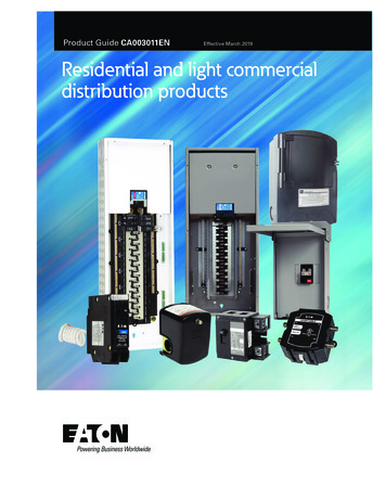
1300 2.5-Inch and M.2 NAND Flash SSDGeneral DescriptionGeneral DescriptionMicron’s solid state drive (SSD) uses a single-chip controller with a SATA interface onthe system side and up to four channels of Micron NAND Flash internally. Available inboth M.2 and 2.5-inch form factors, the SSD integrates easily in existing storage infrastructures.The SSD is designed to use the SATA interface efficiently during both READs andWRITEs while delivering bandwidth-focused performance. SSD technology enables enhanced boot times, faster application load times, reduced power consumption and extended reliability.The self-encrypting drive (SED) features AES-256 encryption engine, providing hardware-based, secure data encryption, with no loss of SSD performance. This SED followsthe TCG/Opal specification for trusted peripherals.When TCG/Opal features are not enabled, the device can perform alternate data encryption by invoking the ATA security command set encryption features, to provide fulldisk encryption (FDE) managed in the host system BIOS. TCG/Opal and ATA securityfeature sets cannot be enabled simultaneously.The data encryption is always running; however, encryption keys are not managed andthe data is not secure until either TCG/Opal or ATA security feature sets are enabled.Figure 2: Functional Block CCM005-731836775-105321300 ssd.pdf - Rev. A 9/18 EN4Micron Technology, Inc. reserves the right to change products or specifications without notice. 2018 Micron Technology, Inc. All rights reserved.
1300 2.5-Inch and M.2 NAND Flash SSDPerformancePerformanceMeasured performance can vary for a number of reasons. The major factors affectingdrive performance are the capacity of the drive and the interface of the host. Additionally, overall system performance can affect the measured drive performance. Whencomparing drives, it is recommended that all system variables are the same, and onlythe drive being tested varies.Performance numbers will vary depending on the host system configuration.For SSDs designed for the client computing market, Micron specifies performance infresh-out-of-box (FOB) state. Data throughput measured in steady state may be lowerthan FOB state, depending on the nature of the data workload.For a description of these performance states and of Micron's best practices for performance measurement, refer to Micron's technical marketing brief, Best Practices forSSD Performance Measurement.Table 1: Drive PerformanceCapacity256GB512GBInterface Speed1024GB2048GB6 Gb/sPCMark vantageUnit86,00086,00086,00086,000HDD scoreSequential read (128KB transfer)530530530530MB/sSequential write (128KB transfer)520520520520MB/sRandom read (4KB transfer)58,00090,00090,00090,000IOPSRandom write (4KB transfer)87,00087,00087,00087,000IOPSREAD latency (TYP)85858585µsWRITE latency (TYP)40404040µsNotes:CCM005-731836775-105321300 ssd.pdf - Rev. A 9/18 EN1. Performance numbers are maximum values, except as noted.2. Typical I/O performance numbers as measured using Iometer with a queue depth of 32and write cache enabled. Fresh-out-of-box (FOB) state is assumed. For performancemeasurement purposes, the SSD may be restored to FOB state using the SECURE ERASEcommand.3. Performance measurements are performed on an 20GB span of logical block addresses(LBAs).4. 4KB transfers with a queue depth of 1 are used to measure READ/WRITE latency valueswith write cache enabled.5. System variations will affect measured results. For comparison, PCMark scores are measured with the SSD as a secondary drive in a two-drive system. When measured as an OSdrive, system overhead can cause lower scores.5Micron Technology, Inc. reserves the right to change products or specifications without notice. 2018 Micron Technology, Inc. All rights reserved.
1300 2.5-Inch and M.2 NAND Flash SSDLogical Block Address ConfigurationLogical Block Address ConfigurationThe drive is set to report the number of logical block addresses (LBA) that will ensuresufficient storage space for the specified capacity. Standard LBA settings, based on theIDEMA standard (LBA1-03), are shown below.Table 2: Standard LBA SettingsTotal LBACapacityUser AvailableBytesMax 20CCM005-731836775-105321300 ssd.pdf - Rev. A 9/18 EN6Micron Technology, Inc. reserves the right to change products or specifications without notice. 2018 Micron Technology, Inc. All rights reserved.
1300 2.5-Inch and M.2 NAND Flash SSDReliabilityReliabilityMicron’s SSDs incorporate advanced technology for defect and error management.They use various combinations of hardware-based error correction algorithms andfirmware-based static and dynamic wear-leveling algorithms.Over the life of the SSD, uncorrectable errors may occur. An uncorrectable error is defined as data that is reported as successfully programmed to the SSD but when it is readout of the SSD, the data differs from what was programmed.Table 3: Uncorrectable Bit Error RateUncorrectable Bit Error RateOperation1015READ 1 sector perbits readMean Time To FailureMean time to failure (MTTF) for the SSD can be predicted based on the component reliability data using the methods referenced in the Telcordia SR-332 reliability predictionprocedures for electronic equipment.Table 4: MTTFMTTF (Operating Hours)1Capacity256GB1.5 21300 ssd.pdf - Rev. A 9/18 EN1. The product achieves a mean time to failure (MTTF) of 1.5 million hours, based on population statistics not relevant to individual units.7Micron Technology, Inc. reserves the right to change products or specifications without notice. 2018 Micron Technology, Inc. All rights reserved.
1300 2.5-Inch and M.2 NAND Flash SSDReliabilityEnduranceEndurance for the SSD can be predicted based on the usage conditions applied to thedevice, the internal NAND component cycles, the write amplification factor, and thewear-leveling efficiency of the drive. The table below shows the drive lifetime for eachSSD capacity by client computing and sequential input and based on predefined usageconditions.Table 5: Drive Lifetime – Client ComputingCapacityDrive Lifetime (Total Bytes :CCM005-731836775-105321300 ssd.pdf - Rev. A 9/18 EN1.2.3.4.1TB 1,000,000,000,000 bytesTotal bytes written validated with the drive 90% full.SSD volatile write cache is enabled.Access patterns used during reliability testing are 25% sequential and 75% random andconsist of the following: 1% are 512B; 44% are 4 KiB; 35% are 64 KiB; and 20% are 128KiB.5. Host workload parameters, including write cache settings, I/O alignment, transfer sizes,randomness, and percent full, that are substantially different than the described notesmay result in varied endurance results.6. GB/day can be calculated by dividing the total bytes written value by the number ofdays in the interval of interest (365 days number of years). For example: 100 TB/3years/365 days 91 GB/day for 3 years.8Micron Technology, Inc. reserves the right to change products or specifications without notice. 2018 Micron Technology, Inc. All rights reserved.
1300 2.5-Inch and M.2 NAND Flash SSDElectrical CharacteristicsElectrical CharacteristicsEnvironmental conditions beyond those listed may cause permanent damage to the device. This is a stress rating only, and functional operation of the device at these or anyother conditions above those indicated in the operational sections of this specificationis not implied. Exposure to absolute maximum rating conditions for extended periodsmay affect reliability.Table 6: SATA Power ConsumptionCapacityDevice SleepTypicalIdle AverageActive AverageActive Maximum(128KB 5002048GB101101753700Notes:mW1. Data taken at 25 C using a 6 Gb/s SATA interface.2. Active average power measured while running MobileMark productivity suite.3. Device-initiated power management (DIPM) enabled. DIPM slumber and DEVSLP enabled.4. Active maximum power is an average power measurement performed using Iometerwith 128KB sequential write transfers.Table 7: Maximum tage input, 2.5-inchV54.55.5V–Voltage input, M.23V33.143.46V–Operating temperatureTC070 C1Non-operating temperature––4085 C–Rate of temperature change––20 C/hour–Relative humidity (non-condensing)–595%–Note:1. Operating temperature is best measured by reading the SSD's on-board temperaturesensor, which is recorded in SMART attribute 194 (0xC2).Table 8: Shock and ting shock1500G/0.5msRotary vibration, non-operatingCCM005-731836775-105321300 ssd.pdf - Rev. A 9/18 EN5–800Hz @ 3.13GRMS9Micron Technology, Inc. reserves the right to change products or specifications without notice. 2018 Micron Technology, Inc. All rights reserved.
1300 2.5-Inch and M.2 NAND Flash SSDDynamic Write AccelerationDynamic Write AccelerationDynamic write acceleration optimizes SSD performance for typical client-computingenvironments, where WRITE operations tend to occur in bursts of commands with idletime between these bursts.Capacity for accelerated performance is derived from the adaptive usage of the SSD'snative NAND array, without sacrificing user-addressable storage. Recent advances inMicron NAND technology enable the SSD firmware to achieve acceleration through onthe-fly mode switching between SLC and TLC modes to create a high-speed SLC poolthat changes in size and location with usage conditions.During periods of idle time between write bursts, the drive may free additional capacityfor accelerated write performance. The amount of accelerated capacity recovered during idle time depends on the portion of logical addresses that contain user data andother runtime parameters. In applications that do not provide sufficient idle time, thedevice may need to perform SLC-to-TLC data migration during host activity.Under accelerated operation, write performance may be significantly higher than nonaccelerated operations. Power consumption per-byte written is lower during accelerated operation, which may reduce overall power consumption and heat production.CCM005-731836775-105321300 ssd.pdf - Rev. A 9/18 EN10Micron Technology, Inc. reserves the right to change products or specifications without notice. 2018 Micron Technology, Inc. All rights reserved.
1300 2.5-Inch and M.2 NAND Flash SSDAdaptive Thermal MonitoringAdaptive Thermal MonitoringThe device features adaptive thermal monitoring. While most host computers exhibitoperating environments that keep an SSD running in the range of 40 C to 45 C, adaptive thermal monitoring enables the SSD to operate in a wide variety of environmentsby helping to prevent the host computer from running at excessive temperatures.Adaptive thermal monitoring reduces total SSD power consumption by injecting timebased delays between internal processing of media commands when the device temperature exceeds its operating specification. The delay times used are bound to the microsecond range and are based on a proportional and differential control equation ofthe general form shown here:u(t) Kp Tp(t) Kd dTddtThe delay-control equation is tuned for a steady-state temperature target, which hasbeen designed as an optimum balance of hardware temperature tolerances and driveperformance. Steady-state temperature targets are hardware-configuration dependentand may range around 80 C. Temperatures below the intended steady-state target willnot produce a proportional component delay, but may produce a differential component based on the current rate of temperature change according to the control equation. When the feature is active, DRAM refresh rates are also adjusted to improve dataintegrity and stability while operating outside of temperature specifications.When the device temperature returns within the operating limits, normal operation willcontinue without induced delays. If the temperature continues to rise above the temperature target and exceeds a hardware-dependent critical threshold, the device willabort host commands to prevent component damage.Device temperature values used by the adaptive thermal monitoring feature are basedon an internal temperature sensor located on the device PCB and may differ from caseor package temperatures as measured by a thermocouple. Device temperature is accessible through SMART attribute 194, though usage of the SMART feature is not necessaryfor adaptive thermal monitoring functionality.Adaptive thermal monitoring does not change the current negotiated speed of the SATAbus, nor require or cause any new commands to be issued on the SATA bus. Ratedthroughput performance is not guaranteed at any point above the maximum specifiedoperating temperature.CCM005-731836775-105321300 ssd.pdf - Rev. A 9/18 EN11Micron Technology, Inc. reserves the right to change products or specifications without notice. 2018 Micron Technology, Inc. All rights reserved.
1300 2.5-Inch and M.2 NAND Flash SSDTCG/Opal SupportTCG/Opal SupportTable 9: TCG/Opal Support ParametersPropertySupported?CommentsTCG Storage SpecificationsOPAL: TCG Storage Security SubSystemClassSpecification 2.00Revision 1.00, Feb 24, 2012TCG Core SpecificationSpecification 2.00Revision 2.00, Nov 4, 2011TCG Storage Interface Interactions SpecificationTCG ReferenceSpecificationSpecification Version 1.02 Revision 1.00 30 December, 2011OPAL SSC 1.00 (backward compatibility)Not supported–OPAL SSC Additional Feature Set SpecificationAdditional DataStore TableSupportedSpecification 1.00 Revision 1.00, Feb 24, 2012Single User ModeSupportedSpecification 1.00 Revision 1.00, Feb 24, 2012TCG Storage Protection Mechanisms forSecretsSupportedSpecification Version 1.00 Revision 1.07 17 August,2011PSID – Physical Presence SIDSupportedSpecification Version 1.00 Committee Draft Revision 1.05 February 9, 2011GUDID (Globally Unique Serial Number)SupportedMandatory GUDID Proposal 11/03/2011 (Microsoft)SID Authority DisableSupportedSID Authority Disable Proposal 9/26/2011 (Microsoft)Modifiable CommonName ColumnsSupportedModifiable CommonName Columns Proposal7/22/2010 (Microsoft)ALL OPAL Mandatory FeaturesSupported–Close Session (optional)SupportedAllows TPer to notify the host it has aborted a sessionOPAL SSC Feature Set – Specific ListRestricted Command & Table (optional)Not SupportedThe interface control template enables TPer controlover selected interface commands; the benefit isthe reduction of undesired side effectsType Table (not required)Not Supported–Activate MethodSupported–Revert MethodSupported–Revert SP MethodSupported–Activate Method Within TransactionsNot SupportedAs per OPAL, this behavior is out of the scopeRevert Method within TransactionsNot SupportedAs per OPAL, this behavior is out of the scopeRevert SP Method within TransactionsNot SupportedAs per OPAL, this behavior is out of the scopeCreation/Deletion of Tables/Rows afterManufacturingNot SupportedAs per OPAL, this behavior is out of the scopeCOM ID Management SupportNot SupportedDynamic COM ID allocation & management notsupportedBuffer Management SupportNot SupportedFlow controlTPer FeatureCCM005-731836775-105321300 ssd.pdf - Rev. A 9/18 EN12Micron Technology, Inc. reserves the right to change products or specifications without notice. 2018 Micron Technology, Inc. All rights reserved.
1300 2.5-Inch and M.2 NAND Flash SSDTCG/Opal SupportTable 9: TCG/Opal Support Parameters (Continued)PropertySupported?CommentsACK/NACK SupportNot SupportedSession reliabilityAsync SupportNot SupportedAsynchronous protocol support with multiple commands per sessionGeometry Reporting FeatureALIGNSupportedAlignment is not requiredLogical Block Size512 bytesLogical block size 512 bytesAlignment Granularity512 bytesLogical block size 512 bytesLowest Aligned LBA0–OPAL SSC V2.00 Feature DescriptorBase COM ID0x10000x1000-0xFFFF defined for COM ID managementNumber of COM IDs1–Range Crossing Behavior0If drive receives a READ or WRITE command thatspans multiple LBA ranges and the LBA ranges arenot locked, then:1. Process the data transfer, if Range Crossing 02. Terminate the command with “Other InvalidCommand Parameter” if Range Crossing 1Number of Locking SP Admin AuthoritiesSupported4As per OPAL 2.0, drive should support at least 4 adminNumber of Locking SP User AuthoritiesSupported16As per OPAL 2.0, drive should support at least 8usersInitial C PIN SID PIN Indicator0x000x00 The initial C PIN SID PIN value is equal tothe C PIN MSID PIN value0xFF The initial C PIN SID PIN value is VU, andMAY not be equal to the C PIN MSID PIN valueOPAL 2.0 (only)Customer-specific SID – ConfigurableBehavior of C PIN SID PIN upon Ter Revert0x000x00 The C PIN SID PIN value becomes the valueof the C PIN MSID PIN column after successful invocation of revert on the admin SP’s object in theSP table0xFF The C PIN SID PIN value changes to a VUvalue after successful invocation of revert on theadmin SP’s object in the SP table and MAY not beequal to the C PIN MSID PIN value OPAL 2.0 (only)Maximum number of DataStore Tables16The maximum number of the DataStore tables thatthe TPer supports, including the DataStore tabledefined in OPAL SSC 2.0Maximum total size of DataStore Tables12MBSpecifies the maximum total size in bytes of all ofthe DataStore tables that TPer supports, includingthe DataStore table defined in OPAL SSC 2.0MBR Table128MB–DataStore Table FeatureCCM005-731836775-105321300 ssd.pdf - Rev. A 9/18 EN13Micron Technology, Inc. reserves the right to change products or specifications without notice. 2018 Micron Technology, Inc. All rights reserved.
1300 2.5-Inch and M.2 NAND Flash SSDTCG/Opal SupportTable 9: TCG/Opal Support Parameters (Continued)PropertySupported?CommentsByte Table Access GranularityMandatory Write GranularityRecommended Access Granularity1TPer enforces when the host invokes the set method on byte tables; it should be less than or equal to8192; it should be less than or equal to Recommended Access Granularity, OPAL 2.0 (only)8192TPer recommends when the host invokes the set orget method on byte tables; it should be less than orequal to 8192256 BitsAES key is generated by using CTR DRBG algorithm(FIPS Compliant)Cryptographic FeaturesAES Key SizeAES ModeNumber of Ranges/Band SupportedRe-EncryptionXTSIV swapped16Unique AES key per range/band; range crossing isallowed if the range is unlockedNot SupportedKey Management–CryptographicCrypto Erase Completion Time 1sYes–Cryptographic Algorithms are Certified byFIPS-197NoDesigned to meet, no plans for certificationAES 256-Bit CBC/ECB ModeSupportedECB mode used only for generating the randomkey by CTR DRBGCTR DRBGSupported–SHA 256Supported–RSA 2048 Signature VerificationSupported–TPer Communication PropertiesMax ComPacket Size131072256 sectors (128K)Max Response ComPacket Size131072256 sectors (128K)Max Packet Size128512–Max Individual Token Size123904–Max Packets1–Max SubPackets1–Max Sessions1Each session requires a set of buffers and variablesMax Transaction Limit1Transaction are inside sessionsMax Methods1Methods are contained in a transactionMax Authentications2121 16 users 4 admins 1 anybodyDef Session TimeoutYesThe session timeout length (in milliseconds) usedby the TPer by defaultIEEE1667Probe SiloSupported–TCG Storage SiloSupported–CCM005-731836775-105321300 ssd.pdf - Rev. A 9/18 EN14Micron Technology, Inc. reserves the right to change products or specifications without notice. 2018 Micron Technology, Inc. All rights reserved.
1300 2.5-Inch and M.2 NAND Flash SSDTCG/Opal SupportTable 9: TCG/Opal Support Parameters (Continued)PropertyOther than Probe and TCG Storage SiloSupported?CommentsNot Supported–IEEE1667 Major Version2–IEEE1667 Minor Version0–Maximum P OUT Transfer Size131072256 sectors (128K)OthersFDE (ATA Security with Key Management)Secure Firmware DownloadCCM005-731836775-105321300 ssd.pdf - Rev. A 9/18 ENYes–Supported15Firmware image is validated by using SHA256 andRSA2048 algorithmMicron Technology, Inc. reserves the right to change products or specifications without notice. 2018 Micron Technology, Inc. All rights reserved.
1300 2.5-Inch and M.2 NAND Flash SSDDevice IDDevice IDTable 10: Identify DeviceSee Note 1 for setting definitionsWordBit(s)SettingDefault Value0DescriptionGeneral configuration bit-significant information15F0b0 ATA 1b5–3X000b2V0bResponse lete2FC837hSpecific configuration3F0010hObsolete4F0000h 0000h6F003Fh7(O)V0000h 0000h9X0000hRetired10(M)FvariesSerial number (20 ASCII characters)20X0000h 0000h0000h23(M)FvariesFirmware revision (8 ASCII characters)27(M)FvariesModel number (40 ASCII characters)15–8F80h80h7–0F10h00h Reserved01h–FFh Maximum number of logical sectors that shall betransferred per DRQ data block on READ/WRITE MULTIPLEcommands.4748CCM005-731836775-105321300 ssd.pdf - Rev. A 9/18 ENRetiredObsoleteReserved for assignment by the CompactFlash AssociationRetired/ObsoleteTrusted Computing feature set options15F14F13–1F0F0bShall be cleared to zero1bShall be set to one0000000000000b Reserved for the Trusted Computing Groupvaries1 Trusted Computing feature set is supportedThis bit will be 1 for TCG drives, otherwise 016Micron Technology, Inc. reserves the right to change products or specifications without notice. 2018 Micron Tech
5. System variations will affect measured results. For comparison, PCMark scores are meas-ured with the SSD as a secondary drive in a two-drive system. When measured as an OS drive, system overhead can cause lower scores. 1300 2.5-Inch and M.2 NAND Flash SSD Performance CCM005-731836775-10532 1300_ssd.pdf - Rev. A 9/18 EN 5