Transcription
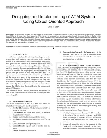
Automatic Digitization of Engineering Diagramsusing Deep Learning and Graph SearchShouvik Mani, Michael A. Haddad, Dan Constantini, Willy Douhard, Qiwei Li, Louis PoirierC3.ai{firstname.lastname}@c3.aiAbstractA Piping and Instrumentation Diagram (P&ID) is a typeof engineering diagram that uses symbols, text, and linesto represent the components and flow of an industrial process. Although used universally across industries such asmanufacturing and oil & gas, P&IDs are usually trappedin image files with limited metadata, making their contentsunsearchable and siloed from operational or enterprise systems. In order to extract the information contained in thesediagrams, we propose a pipeline for automatically digitizing P&IDs. Our pipeline combines a series of computer vision techniques to detect symbols in a diagram, match symbols with associated text, and detect connections betweensymbols through lines. For the symbol detection task, wetrain a Convolutional Neural Network to classify certaincommon symbols with over 90% precision and recall. Todetect connections between symbols, we use a graph searchapproach to traverse a diagram through its lines and discover interconnected symbols. By transforming unstructured diagrams into structured information, our pipelineenables applications such as diagram search, equipmentto-sensor mapping, and asset hierarchy creation. When integrated with operational and enterprise data, the extractedasset hierarchy serves as the foundation for a facility-widedigital twin, enabling advanced applications such as machine learning-based predictive maintenance.1. IntroductionEngineering designs, such as Piping and InstrumentationDiagrams (P&IDs), are used throughout the entire lifecycle of a facility. Created during the engineering and designphase, they are used to communicate requirements throughout the construction and operational phases of an industrialfacility. In many jurisdictions, primarily for safety considerations, there are legal requirements to keep these designs upto date with any changes. Additionally, process engineersrely primarily on P&IDs to understand an industrial processand as a tool to plan and implement process changes. Thesefactors make P&IDs a valuable, up to date ground-truth datasource for the configuration of an industrial facility. However, P&IDs are often archived as hundreds of CAD filesper facility with limited or no metadata describing the components, connections between components, or connectionsbetween P&IDs.As IoT sensors have proliferated throughout industrialfacilities they have become an important element of P&IDs.These sensors, commonly referred to as tags, provide critical, real-time operational data (e.g., temperature, pressure,flow, etc.) and are often connected to locally mounted instruments (LMIs) or installed directly onto equipment. Thisreal-time operational data has become increasingly important for plant management, asset performance management,and process optimization. As machine learning techniquesevolve to extract even more value from this data, contextualizing these tags within diagrams and referencing themto external sensor management systems is an increasinglycritical pre-processing step. For an end user of an AI application to properly interpret machine learning predictionsthey must have a clearly defined asset hierarchy with sensorlocations. For example, when implementing anomaly detection, a well-defined asset hierarchy will enable a user tolocalize an anomalous sensor within a facility and identifya particular component of the machinery.Performing the contextualization step manually onP&IDs is time consuming and error prone. Our digitization pipeline aims to automate this step by combining stateof-the-art computer vision, graph search, and optical character recognition techniques to map the interconnectednessof equipment, pipelines, and sensors within P&IDs. Theoutput of the pipeline, a high-fidelity asset hierarchy, willserve as the foundation for a digital twin used in a multitude of high-value business use cases for machine learninganalytics.P&IDs depict the configuration and properties of allequipment, components (such as valves and insulation),process lines, and instrumentation with standardized symbols related to an industrial process. Connections between
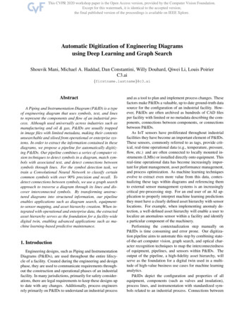
Figure 1. A section of a Piping and Instrumentation Diagram (P&ID). Instrumentation is represented by a circle. Text inside a circleindicates the instrument type and unique ID. Text adjacent to process lines and components specifies size and/or material.P&IDs are marked as inputs or outputs to other equipmentshown on separate P&IDs. Our digitization pipeline doesnot attempt to map all these connections and symbols, butrather focuses on a subset of equipment and instrumentation relationships that are of value for analytical applications. Symbols of interest for our digitization pipeline areshown in Figure 1: (A) locally mounted instrument (LMI)sensor for in-field readings, (B) electrical signal between instruments, (C) sensor (or tag) represented in a database, (D)process line, (E) equipment (such as a vessel, or pump).2. Related workDigitization of complex engineering diagrams has beenan active area of research long before the recent adoption ofdeep learning techniques. In their survey paper, MorenoGarcı́a et al. describe the motivations and challenges inengineering diagram digitization and provide an extensivereview of methods for the digitization problem [6]. Theauthors insist that the automatic analysis and processing ofengineering diagrams is far from being complete and callfor the application of deep learning in this domain. Additionally, they mention a set of contextualization challengesconcerning the connectivity of symbols in diagrams whichare not addressed by the current literature.Most of the prior work on diagram digitization was priorto the popularization of deep learning and featured tra-ditional computer vision techniques. The older methodsachieved reasonable results but were limited in their application as they were inflexible across different diagramdrafting standards and between companies. Our methodis designed to be extendable to any diagram drafting standards and requires only a small number of labeled diagrams.Therefore, users can hand label a limited set of diagramsfrom any company and parse them effectively. Recent approaches have also leveraged deep learning for symbol andtext detection with relatively high precision and recall. Weextend upon these works by using a different CNN for symbol detection and a graph search approach to determine theinterconnections between symbols.While there exists a vast literature on symbol and textdetection in engineering diagrams, there are relatively fewexamples that address the problem of connection detection.Some approaches use a simple Euclidean distance approachto assign symbols as connected symbols if they are within apredefined threshold distance of each other [3]. While thisis sometimes a reasonable heuristic, it fails when applied todense, complex P&IDs in which symbols may be close toeach other but not connected via lines – the ultimate indicator of connectivity. To address this limitation, our pipelinefeatures a graph search approach which traverses the diagram through its solid and dashed lines and only markssymbols as connected if there is a valid path between them.
A similar approach is implemented by Cardoso et al., whodetect staff lines in musical scores by representing the music sheet image as a graph and identifying the shortest connected paths of black pixels in the image graph [1].Most prior work in this field addressed a specific partof the digitization process such as symbol or text detection; an exception is the pipeline proposed by Rahul etal. which performs symbol detection, text detection, andsymbol-to-line association [7]. Their pipeline uses state-ofthe-art deep learning models such as the Connectionist TextProposal Network (CTPN) for text detection and a FullyConvolutional Network (FCN) for symbol detection. Whilewe share the common objective of completely digitizingP&IDs, our methods for symbol detection are noticeablydifferent. Their pipeline uses an FCN which performs image segmentation to segment out symbols of interest usinga 19-layer VGG-19 architecture which requires them 7000epochs to train. Instead of doing segmentation, we classifysymbols directly and use a much lighter CNN.Other examples of pipelines include the system proposedby Kang et al., which uses relatively simple methods suchas template matching to detect symbols and a sliding window approach to detect lines and text [4]. Although easyto implement, template matching approaches either fail togeneralize well due to minor differences in visual appearances between symbols across diagrams or require a vastsymbol library (i.e. the templates) to perform well. Finally,Daele et al. present a promising approach for similaritybased search in CAD drawings by developing a pipeline toextract components using image segmentation and objectrecognition, parse properties from tabular data in the drawings, and represent the extracted information in a featurevector to facilitate similarity comparisons [2].3. MethodologyThere are three steps in our diagram digitizationpipeline: symbol detection, text recognition and association, and connection detection. The inputs to the pipelineare a diagram image and an optional set of manually-labeledsymbols in the diagram. The manually-labeled symbols areones that are of interest to the user but are not among thesymbols automatically detected during the symbol detection step. An example of a snippet from an input diagramand a manually-labeled symbol is shown in Figure 2.In this section, we describe each step of the pipeline anddemonstrate how each step transforms the input diagramsnippet in Figure 2 into intermediate outputs. The final output of the pipeline, presented in Table 1, is an asset hierarchy table containing all information extracted from the diagram snippet. See Appendix A for the asset hierarchy tableon the entire diagram.Figure 2. A snippet from an input diagram with a manually-labeledsymbol (green).3.1. Symbol detectionThe goal of the symbol detection step is to automate theidentification of frequently appearing symbols in diagrams.Two of the most common and useful symbols in P&IDs aretags and LMIs. In this set of diagrams, a tag is the digitalrepresentation of a sensor in the facility and is representedby a circle inscribed in a square. An LMI is a physical instrument such as a pressure gauge or temperature readingand is represented by a circle. Tags and LMIs are importantbecause they often have corresponding entries in time seriessensor databases. By identifying the tag and LMI symbolsin a diagram we can localize sensor data to specific equipment or sections of a facility.In order to train and validate a machine learning modelto detect and classify tags and LMIs, we created a datasetof symbol crops from a collection of 18 P&IDs. Tags andLMIs across the diagrams had a constant size and fit withina 100 x 100-pixel window. So, we labeled all the tags andLMIs in the 18 diagrams using 100 x 100-pixel boundingboxes, resulting in 308 tag crops and 687 LMI crops. Additionally, we took 100 random crops that did not containa tag or LMI symbol from each diagram, resulting in 1800“not symbol” crops. Examples of crops in each of the threeclasses are given in Figure 3.Using our dataset of symbol crops, we trained a Convolutional Neural Network (CNN) to perform a three-wayclassification task: to determine whether an input imagecontained a tag, LMI, or no symbol. We designed asimple CNN architecture with three convolutional layers(with ReLU activations and max pooling) and two fullyconnected dense layers. The first hidden layer had 64 unitswith ReLU activations. The final output layer had threeunits with softmax activations to predict the probability thatthe input image belonged to each of the three classes. This
Figure 3. Examples of crops in each of the three classes.architecture, shown in Figure 4, was inspired by the LeNetarchitectures popularized for digit recognition [5], as weexpected the complexity of diagram symbols to be similarto that of handwritten digits. The network had a total of437,923 parameters.Figure 5. The training and validation loss converged by 100 epochsof training.multiple symbols detected in overlapping windows to a single detected symbol. Finally, the predicted probabilities arethresholded, using a predefined threshold for each symbolclass, to convert the probabilities into a discrete symbolclassification. Windows with predicted probabilities lessthan all thresholds are classified as not symbol.Figure 4. The CNN architecture used for symbol detection.Given the limited number of training examples, we useddata augmentation and dropout to achieve a more robustand generalizable model. We augmented the training examples by rotating, shifting, shearing, zooming, and flipping to make the network invariant to these transformations.Dropout was applied in the dense layers to add some regularization and improve the network’s generalization performance. We randomly split the symbol crops dataset intotraining (60%) and validation (40%) sets and trained thenetwork to minimize cross-entropy loss on the validationset. As shown in Figure 5, both the training and validation loss had converged by 100 epochs of training. We thencombined the training and validation sets and trained a finalmodel on the entire dataset for 100 epochs.To apply the trained CNN to detect symbols in a new diagram, we first slide over the diagram image with a smallstride length and generate all 100 x 100-pixel windowsfrom the input diagram. Because most of the diagram issparse, we filter out windows which are over 90% blankand automatically classify them as “not symbol.” The remaining dense windows are processed through the CNN toproduce predicted probabilities of belonging to each symbol class. Non-maximum suppression is applied to resolveFigure 6 shows the results of symbol detection on theinput diagram snippet. The detected tag and LMI symbolsare displayed in red. Nearly all of the predicted symbols arecorrectly classified, except for symbol 39, which is not anLMI (LMI are circles, not ovals).3.2. Text Recognition and AssociationText is a crucial element in P&IDs which identifies anddescribes elements in the diagrams. For instance, the textinside the tag symbols often serves as a key to fetch data forthe tag from a time series sensor database. Text is also usedto specify the length and diameter of pipes in the diagram.Because of the importance of text, an digitization of the diagram is not complete without recognizing and interpretingtext, as well as associating it with detected symbols in thediagram.To detect text in the diagram, we use Efficient and Accurate Scene Text Detector (EAST) [8], a state-of-the-artpipeline which uses a neural network to produce boundingboxes where text is present in an image. The text boundingboxes generated by EAST on the input diagram snippet aredisplayed in blue in Figure 6. For each symbol, we identifyassociated text based on the proximity of the symbol to textbounding boxes using a distance threshold. Associated textfor each symbol is then interpreted using Tesseract OCR,and the results are added to the extracted information in theasset hierarchy in Table 1.
Figure 6. The diagram snippet with detected symbols (red), detected text (blue), and manually-labeled symbols (green).3.3. Connection DetectionSymbols in the diagram are connected to each other via adense network of lines. While solid lines indicate physicalconnections such as pipes transporting fluids, dashed linesindicate digital connections such as equipment-to-sensor relationships. The connection detection step builds on thesymbol detection step and determines which symbols areconnected to each other via lines. This final step in thepipeline is essential for digitally reconstructing the relationships in the diagram and creating an asset hierarchy.We use a graph search approach for connection detection. First, the thresholded diagram image is represented asa graph. In this diagram graph, nodes are individual pixelsin the diagram. Each node contains information on whetherit is black or white (based on its thresholded pixel intensity) and whether it is part of a symbol (and if so, whichone). The graph’s edges are links between neighboring pixels, with a maximum of eight edges per node. Symbolsare represented in the graph as a collection of nodes corresponding to the pixels that form the symbol.With this graph representation of the diagram, connections between symbols can be identified through a depthfirst search (DFS). Specifically, for each detected symbol,a DFS is initialized from one of the nodes in the symbol.The DFS traverses the diagram graph along its black nodes,hitting (and keeping track of) connected symbols along itspath. The search terminates once all valid paths are exhausted.Figure 7 shows the result of running connection detection on the diagram snippet, with the source symbol in red,the connected symbols in green, and the paths traversed byDFS to reach the connected symbols from the source symbol in blue. Note that all detected symbols except for theoval symbol are identified as connected to the source sym-Figure 7. Connections detected between a source symbol (red) andconnected symbols (green) through lines traversed by depth-firstsearch (blue).bol, which is correct as there are no continuous paths between those two symbols. We run connection detectionstarting at every symbol in the diagram and populate theentire list of connected symbols in the asset hierarchy inTable 1. In Table 1, we represent this information by listingthe ids of connected symbols from each source symbol.3.4. Diagram-to-Diagram RelationshipsFor large facilities or systems, multiple P&ID diagramswill collectively represent the components and flow of anindustrial process. In these cases, in addition to the digitization of intra-diagram relationships, diagram-to-diagram relationships are also desired. Our approach is to convert theproblem into a symbol detection task and a text recognitionand association task. Diagram-to-diagram relationships areoften indicated by reserved symbols as shown in Figure 8.The symbol representing the connection to a downstreamdiagram is a right-pointing arrow box and the symbol forthe connection to an upstream diagram is represented as aleft-pointing arrow box.Figure 8. Inlet and outlet symbols represent connections to otherdiagrams.Our methodology discussed in the previous Symbol De-
Symbol idMethodSymbol typeAssociated textConnected edDetectedDetectedDetectedTAGTAGLMILMILMI33, 5, 7, 9, 41, 11, 13, 16,18, 20, 25, 26, 2.16, 33, 1425, 3, 20, 53, 7, 41, 24, 26, 283, 5, 13, 25, tectedDetectedDetectedLMILMILMILMILMILMILMI3030, 321, CO, E“X6F, XVZ, E.,XJA, BX6F, 303,.3I077L?, XJA, 303J3023, RV, 1251C, 3%3I07, XVI, MOE.9, 13030, XVZ, BX6F, UFOZ, E, J91,E, RIÉ.0OP§IC, RV, CO, 355, 1533, —2MXVZ, E., 303, 303, E303, 303, MOE.9E“X6F, E347M.OE, MOVIÉO, JN, ZO5MOE.95, 3, 20, 1316, 41, 3, 2816, 41, 26, 33, 2018, 334, 216, 26, 3, 28Table 1. The output of the pipeline is an asset hierarchy table populated with information extracted from the diagram snippet in Figure 2.tection section can be applied. Second, we realize that formost P&IDs, the diagram names follow convention and always appear with the diagram-to-diagram connection symbols. As shown in Figure 8, we see the connected P&IDdiagram names (DWG Number) are very structured. Thecombination of our methodology discussed in the previousText Recognition and Association section and some regularexpressions can be applied to link diagrams by their names.provided in Appendix B.4. ResultsWe evaluated our symbol detection procedure on the18 training diagrams and 11 diagrams in a held-out testset. Symbols were considered correctly classified if the detected symbol’s class matched the ground truth label and thedetected symbol’s bounding box had an intersection overunion (IOU) of at least 0.5 with the ground truth symbol’sbounding box. In the 11 unseen test diagrams, tags wereclassified with 100% precision and 98% recall using a classification probability threshold of 0.95. LMIs were classified with 85% precision and 90% recall using a classification probability threshold of 0.95.Precision-recall curves in Figure 9 summarize the classification performance for each symbol class over multipleprobability thresholds in the training and test diagrams. Tagclassification performance is considerably better than LMIclassification performance since many circular-shaped symbols which are not LMIs are incorrectly classified as LMIs,driving down the precision of LMI classification. Tags, onthe other hand, are consistently represented by a distinctcircle-inside-square symbol and are less prone to gettingconfused for other symbols. A full comparison between thedetected symbols and ground truth symbols in a diagram isFigure 9. Precision-recall curves show the classification performance for each symbol class on the 18 training diagrams and 11test diagrams.5. ConclusionIn this paper, we have presented an automatic digitization pipeline for P&IDs. Our pipeline combines state-ofthe-art computer vision methods to detect symbols, recognize and interpret text, and detect connections betweensymbols through lines. To the best of our knowledge, ourpipeline is the first to apply graph search to detect connections between symbols in P&IDs. Moreover, our symboldetection CNN model achieves high levels of precision andrecall and is easily extensible to additional symbol classes.There are several future research directions which shouldbe pursued to improve the accuracy and scalability of P&ID
digitization. First, leveraging a binary object detectionCNN such as FasterRCNN to detect symbol/not-a-symbolwould not only improve the performance of the end classifier but also reduce the overhead from the sliding window.Second, we need to develop sample-efficient symbol detection models which can learn to classify symbols from onlya handful of examples instead of hundreds. Recent work infew-shot learning techniques may be relevant for this challenge and help scale the symbol detection capability to themyriad symbol classes that appear in P&IDs.Text interpretation can also be made more accurate byproviding a dictionary of known terms in the facility, whichcan help to resolve some of the mistakes made by OCR. Finally, the graph search approach for connection detectioncan be made more robust by integrating simple heuristicssuch as the maximum permissible distance between twoconnected symbols, as well as more complex constraintssuch as the direction of flow of the connecting pipes basedon arrow symbols.The structured asset hierarchy extracted from diagramsusing our pipeline can be used to support a wide range of applications. We envision diagram search applications whichcan help to localize symbols across a large number of diagrams based on just their associated text or symbol type.Predictive maintenance applications for equipment can alsobe supported with valuable knowledge of equipment-totag connections, which can help to train better models forequipment failure. By automatically transforming unstructured diagrams into structured information, our pipeline canunlock the value of these diagrams for industries and significantly reduce the manual work necessary to digitize andunderstand them.6. AcknowledgementsWe would like to thank Varun Badrinath Krishna formotivating this work and his feedback. We thank ParthanKasarapu and Samaneh Aminikhanghahi for their early advice and discussion on possible techniques. Finally, wethank Mehdi Maasoumy for his continued support and feedback on this project.References[1] J. S. Cardoso, A. Capela, A. Rebelo, and C. Guedes. A connected path approach for staff detection on a music score. In2008 15th IEEE International Conference on Image Processing, pages 1005–1008, 2008. 3[2] Dries Van Daele, Nicholas Decleyre, Herman Dubois, andWannes Meert. An automated engineering assistant: Learning parsers for technical drawings. ArXiv, abs/1909.08552,2019. 3[3] C Howie, J Kunz, T Binford, T Chen, and K.H Law. Computer interpretation of process and instrumentation drawings.Advances in Engineering Software, 29(7):563 – 570, 1998. 2[4] Sung-O Kang, Eul-Bum Lee, and Hum-Kyung Baek. A digitization and conversion tool for imaged drawings to intelligent piping and instrumentation diagrams (p&id). Energies,12(13):2593, Jul 2019. 3[5] Yann LeCun, Bernhard E. Boser, John S. Denker, Donnie Henderson, R. E. Howard, Wayne E. Hubbard, andLawrence D. Jackel. Handwritten digit recognition with aback-propagation network. In D. S. Touretzky, editor, Advances in Neural Information Processing Systems 2, pages396–404. Morgan-Kaufmann, 1990. 4[6] Carlos Francisco Moreno-Garcı́a, Eyad Elyan, and ChrisinaJayne. New trends on digitisation of complex engineeringdrawings. Neural Computing and Applications, 31(6):1695–1712, 2019. 2[7] Rohit Rahul, Shubham Paliwal, Monika Sharma, andLovekesh Vig. Automatic information extraction from pipingand instrumentation diagrams, 2019. 3[8] Xinyu Zhou, Cong Yao, He Wen, Yuzhi Wang, ShuchangZhou, Weiran He, and Jiajun Liang. EAST: an efficient andaccurate scene text detector. CoRR, abs/1704.03155, 2017. 4
to external sensor management systems is an increasingly critical pre-processing step. For an end user of an AI ap-plication to properly interpret machine learning predictions they must have a clearly defined asset hierarchy with sensor locations. For example, when implementing anomaly de-tection, a well-defined asset hierarchy will enable a .