Transcription
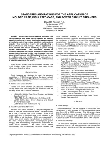
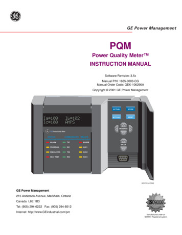
Order this document by MC3361C/D The MC3361C includes an Oscillator, Mixer, Limiting Amplifier,Quadrature Discriminator, Active Filter, Squelch, Scan Control and MuteSwitch. This device is designed for use in FM dual conversioncommunications equipment. LOW POWERNARROWBAND FM IFSEMICONDUCTORTECHNICAL DATAOperates from 2.0 to 8.0 V SupplyLow Drain Current 2.8 mA Typical @ VCC 4.0 VdcExcellent Sensitivity: Input Limiting Voltage –– 3.0 dB 2.6 µV TypicalLow Number of External Parts RequiredOperating Frequency Up to 60 MHz16Full ESD Protection1P SUFFIXPLASTIC PACKAGECASE 648161D SUFFIXPLASTIC PACKAGECASE 751B(SO–16)Representative Block Output161514131211Filter RecoveredInputAudioPIN CONNECTIONS109–FilterAmpSquelch Trigger withHysteresis 116 Mixer Input215 GroundMixer Output3VCCLimiter Input414 Audio Mute13 Scan Control512 Squelch Input611 Filter Output10 Filter Input9 DemodulatorOutputCrystal OscAFAmpDemodulatorDecouplingMixerLimiterAmp10 pF52 k50 k1.8 kQuad Coil78(Top View)Oscillator1.8 k12CrystalOsc345MixerOutputVCCLimiterInputORDERING INFORMATION67DecouplingThis device contains 92 active ngTemperature RangeTA – 30 to 70 CPackageSO–16Plastic DIP Motorola, Inc. 1995MOTOROLA ANALOG IC DEVICE DATA1
MC3361CMAXIMUM RATINGS (TA 25 C, unless otherwise noted.)PinSymbolValueUnitPower Supply Voltage4VCC(max)10VdcOperating Supply Voltage Range4VCC2.0 to 8.0VdcDetector Input Voltage8–1.0Vp–pInput Voltage (VCC16V161.0VRMSMute Function14V14–0.5 to 5.0VpkJunction Temperature–TJ150 COperating Ambient Temperature Range–TA–30 to 70 CStorage Temperature Range–Tstg–65 to 150 CRatingq 4.0 V)ELECTRICAL CHARACTERISTICS (VCC 4.0 Vdc, fo 10.7 MHz, f 3.0 kHz, fmod 1.0 kHz, TA 25 C,unless otherwise noted.)CharacteristicPinDrain Current (No Signal)MinTypMax2.03.72.85.23.56.34Squelch “Off”Squelch “On”UnitmARecovered Audio Output Voltage (Vin 10 mVrms)9130170210mVrmsInput Limiting Voltage ( –3.0 dB Limiting)16–2.66.0µVTotal Harmonic Distortion9–0.86–%Recovered Output Voltage (No Input Signal)960190350mVrmsDrop Voltage AF Gain Loss9– 3.0– 0.6–dBDetector Output Impedance––450–ΩFilter Gain (10 kHz) (Vin 0.3 mVrms)–4050–dBFilter Output Voltage110.50.70.9VdcMute Function Low14–3050ΩMute Function High141.011–MΩScan Function Low (Mute “Off”) (V12 1.0 Vdc)13–00.4VdcScan Function High (Mute “On”) (V12 Gnd)133.03.9–VdcTrigger Hysteresis––45100mVMixer Conversion Gain3–28–dBMixer Input Resistance16–3.3–kΩMixer Input Capacitance16–9.0–pF2MOTOROLA ANALOG IC DEVICE DATA
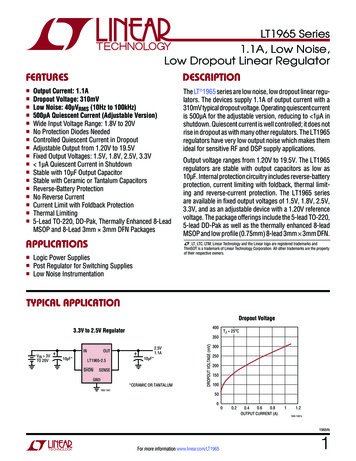
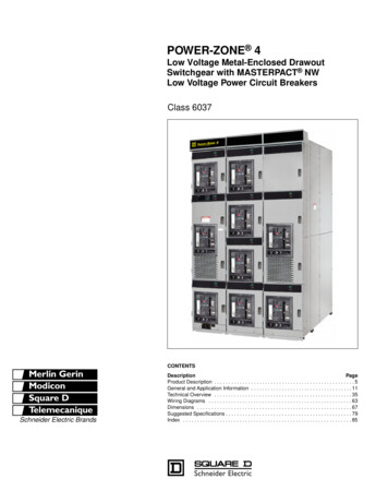
MC3361CFigure 1. Test Circuit10.245 MHz0.01VCC168 pFFL1muRataCFU455D251215314Audio Mute13Scan Control45MC3361C220 pFMixer Input10.7 MHz1610 kSQ SW Input120.11.06110.171089Filter Amp Out 470 k5108.2 k20 kFilter Amp In 1.0AF Output0.010.1Quad CoilFL1 – muRata Erie North America CFU455D2 or equivalentQuadrature Coil – Toko America Type 7MC–8128Z or equivalentC – µF, unless notedFigure 3. Audio Output, Distortionversus Temperature8.01707.06.0Audio .06.0VCC, SUPPLY VOLTAGE (V)MOTOROLA ANALOG IC DEVICE DATA1.08.00240220AUDIO OUTPUT (mVrms)180TA 25 CAUDIO OUTPUT DISTORTION (%)AUDIO OUTPUT (mVrms)1908.0VCC 4.0 V7.02006.01805.0Audio 406020TA, AMBIENT TEMPERATURE ( C)1.00803AUDIO OUTPUT DISTORTION (%)Figure 2. Audio Output, Distortionversus Supply Voltage
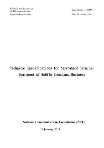
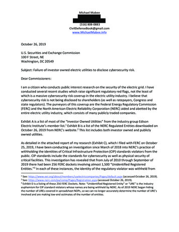
45110.7 MHz1N602200.0110.245MHz1516214Q4R3410 k10C4Q38 Q39Q37R33510Q41Q45R3825 kQ44R371.6 k3.3 kR8Q8R91.4 kQ42Q43R3612 kQ40Q11Q767 ΩR35510Q6Q5R77.0 kR4015 kR39 R4115 k 15 kQ46R101.4 kQ14Q12Q9 Q10Q156.0C1R1110 kR15Q53to C.F.57.5 kR49Q54R477.5 kQ52Q2010R19240Q21R1811 k0.1R51 1.8 kR54750Q57Q55Q566R21150R5610 k0.1R571.6 kQ607Q26C3VCCQ63Q30Q2911R601.6 kR6852 kR69R631.6 kQ66R645.3 kR6610 kR714704.7 kQ71470R73Q73 22 kR72Q70Q74Q72Q35R305.6 kQ34R3140 kQ69 R69Q67Q68R671.6 kR2810 kR2740 kQ33R29180Q32Q31R262.4 kR6510 k1250 kR2524 kR6210 kQ64 Q65R59 R6110 k 10 kQ28Q27R2470Q61Q62R5810 kQ25R23200470 kQ58 Q59R22500Q24Q23R53 R5510 k 10 kR203.0 kQ22R1711 kR5210 kR1610 kQ191.0R48 R501.5 k 1.6 kQ51R4340 kQ49R454.7 kQ18R14250C26.0Q503Q16 Q171.8 kR44 R461.3 k 1.3 kQ48Q47R4220 kR1315 k6.7 kR11Q134510Q79RLQ81Q80R7722 kR791.6 kR811.6 kQ86Q88Q87R801.6 kQ85R781.6 k20 kQuad CoilQ84Q83R751.6 kQ77Q78R741.6 kRLQ82R76620Q75Q76C51081514134Q89R8332 kC6R8282 k915R84560Q91Q904Figure 4.Q36R3250 kQ3Q215 kR1R3R2 15 k R51.4 k1.4 kQ1R6R45.0 k 7.0 kto Pin 5Ceramic FilterFigure 4. Low Voltage Low Power Narrowband FM IF0.013.2 kVCCMC3361CMOTOROLA ANALOG IC DEVICE DATA
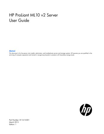
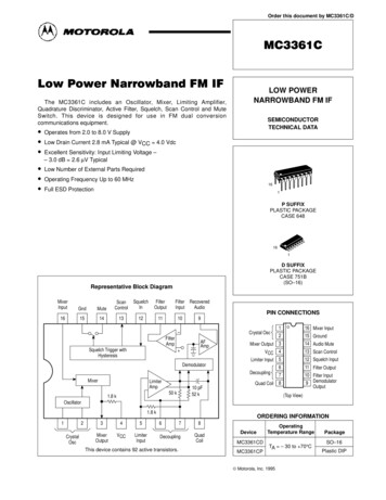
MC3361CFigure 5. Input Limiting VoltageFigure 6. Overall Gain, Noise and AM Rejection1.010VCC 4.0 VAudio Output (1.0 kHz)RELATIVE OUTPUT (dB)– 1.0LIMITING (dB)Referred to 0 dB forS N 3.0 kHz FM00– 2.0– 3.0– 4.0–10–20S N (30% AM)–30–40–50N– 5.0–60– 6.00.001–700.0010.010.1INPUT SIGNAL (mVrms)1.00.01806070506040302010504030201001.0 k1.0Figure 8. Filter Amp Gain70GAIN (dB)GAIN (dB)Figure 7. Filter Amp Response0.1INPUT SIGNAL (mVrms)1010 k100 kf, FREQUENCY (Hz)1.0 M001.02.03.04.05.06.0VCC, SUPPLY VOLTAGE (V)7.08.0Figure 9. Supply CurrentSUPPLY CURRENT (mAdc)8.06.0Squelch “On”4.0Squelch “Off”2.000MOTOROLA ANALOG IC DEVICE DATA6.04.02.0VCC, SUPPLY VOLTAGE (Vdc)8.05
MC3361CFigure 10. Simplified ApplicationScan Controlto PLLVCC 4.0 VR718 kR9100 k1st IF 10.7 MHzfrom InputFront End C124.7R101.0 kR84.7 k C1310C110.1C100.001R151VR2 (Squelch Control)10 kR53.3 kR33.3 kR46.8 kC70.022C90.001R6470 kC80.047C10.01161514131211109678VR122 kAF Outputto AudioPower Amp.MC3361C110.245MHz2345C268 pFC50.1FL1C3220 pFQuad CoilR220 kC40.1Units:R:ΩC : µFunless notedC60.1FL1 – muRata Erie North America Type CFU455D2 or equivalentQuadrature Coil – Toko America Type 7MC–8128Z or equivalent6MOTOROLA ANALOG IC DEVICE DATA
MC3361COUTLINE DIMENSIONSP SUFFIXPLASTIC PACKAGECASE 648–08ISSUE RNOTES:1. DIMENSIONING AND TOLERANCING PER ANSIY14.5M, 1982.2. CONTROLLING DIMENSION: INCH.3. DIMENSION L TO CENTER OF LEADS WHENFORMED PARALLEL.4. DIMENSION B DOES NOT INCLUDE MOLD FLASH.5. ROUNDED CORNERS ATINGPLANEKHGDMJ16 PL0.25 (0.010)T 0.0210.0400.700.100 BSC0.050 21.772.54 BSC1.27 BSC0.210.382.803.307.507.740100.511.01D SUFFIXPLASTIC PACKAGECASE 751B–05(SO–16)ISSUE J–A–16NOTES:1. DIMENSIONING AND TOLERANCING PER ANSIY14.5M, 1982.2. CONTROLLING DIMENSION: MILLIMETER.3. DIMENSIONS A AND B DO NOT INCLUDEMOLD PROTRUSION.4. MAXIMUM MOLD PROTRUSION 0.15 (0.006)PER SIDE.5. DIMENSION D DOES NOT INCLUDE DAMBARPROTRUSION. ALLOWABLE DAMBARPROTRUSION SHALL BE 0.127 (0.005) TOTALIN EXCESS OF THE D DIMENSION ATMAXIMUM MATERIAL CONDITION.9–B–1P8 PL0.25 (0.010)8MBSGRKFX 45C–T–SEATINGPLANEMD16 PL0.25 (0.010)MT BSMOTOROLA ANALOG IC DEVICE 04.001.351.750.350.490.401.251.27 .050 BSC0.0080.0090.0040.009070.2290.2440.0100.0197
MC3361CMotorola reserves the right to make changes without further notice to any products herein. Motorola makes no warranty, representation or guarantee regardingthe suitability of its products for any particular purpose, nor does Motorola assume any liability arising out of the application or use of any product or circuit,and specifically disclaims any and all liability, including without limitation consequential or incidental damages. “Typical” parameters can and do vary in differentapplications. All operating parameters, including “Typicals” must be validated for each customer application by customer’s technical experts. Motorola doesnot convey any license under its patent rights nor the rights of others. Motorola products are not designed, intended, or authorized for use as components insystems intended for surgical implant into the body, or other applications intended to support or sustain life, or for any other application in which the failure ofthe Motorola product could create a situation where personal injury or death may occur. Should Buyer purchase or use Motorola products for any suchunintended or unauthorized application, Buyer shall indemnify and hold Motorola and its officers, employees, subsidiaries, affiliates, and distributors harmlessagainst all claims, costs, damages, and expenses, and reasonable attorney fees arising out of, directly or indirectly, any claim of personal injury or deathassociated with such unintended or unauthorized use, even if such claim alleges that Motorola was negligent regarding the design or manufacture of the part.Motorola andare registered trademarks of Motorola, Inc. Motorola, Inc. is an Equal Opportunity/Affirmative Action Employer.How to reach us:USA / EUROPE: Motorola Literature Distribution;P.O. Box 20912; Phoenix, Arizona 85036. 1–800–441–2447JAPAN: Nippon Motorola Ltd.; Tatsumi–SPD–JLDC, Toshikatsu Otsuki,6F Seibu–Butsuryu–Center, 3–14–2 Tatsumi Koto–Ku, Tokyo 135, Japan. 03–3521–8315MFAX: RMFAX0@email.sps.mot.com – TOUCHTONE (602) 244–6609INTERNET: http://Design–NET.comHONG KONG: Motorola Semiconductors H.K. Ltd.; 8B Tai Ping Industrial Park,51 Ting Kok Road, Tai Po, N.T., Hong Kong. 852–266292988 *MC3361C/D*MC3361C/DMOTOROLA ANALOG IC DEVICEDATA
y14.5m, 1982. 2. controlling dimension: millimeter. 3. dimensions a and b do not include mold protrusion. 4. maximum mold protrusion 0.15 (0.006) per side. 5. dimension d does not include dambar protrusion. allowable dambar protrusion shall be 0.127 (0.005) total in excess of the d dimension