Transcription
Guide lines for monitoringRock surface temperature (RST) onsteep rockwallDraft versionDefinitionOn steep bedrock slopes (rockwalls) the Ground Surface Temperature (GST) is defined as the surfaceor near-surface temperature of the bedrock measured in the uppermost (up to 10) centimeters.Relevant parametersThe Mean Annual Ground Surface Temperature (MAGST) can be reasonably used as a first proxy ofpermafrost presence/absence because of the absence of snow or debris covers. As suggested in thePermafrost Evidences Database instructions the certainty of premafrost occurrence can be defined asfollow:Certainty for Permafrost Yes-2 C MAGST 0 C: Quite likelyMAGST -2 C: Quite certainCertainty for Permafrost No0 C MAGST 2 C: Quite likelyMAGST 2 C: Quite certainOn slopes with steepness greater than 60 the MAGST can be corrected by the Mean Annual AirTemperature (MAAT) anomaly derived from hystorical air temperature observations. This correctionprocedure is described in the PED instructionsMeasurement techniquesInstrumentsOn steep slopes the RST is measured by autonomous mini-datalogger powered by batteries. In thisguidelines 3 differing solutions are presented.The 1st uses a single-thermistor string specifically designed for permafrost monitoring on rockwall(Fig. 1). The rock temperature is measured at 10cm of depth and logged by the M-Log5W minilogger. Sensor type: PT1000, accuracy /- 0.1 C, resolution 0.01 C.
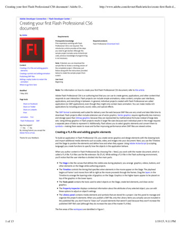
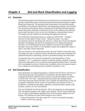
Fig. 1 – Mini-logger M-Log5W-ROCK by geoprecisionThe 2nd and 3rd solutions use a multi-thermistor string cabled to an M-Log5W mini-logger (Fig. 2 and4A) and to an iLog-3V-GPRS datalogger (Fig. 3 and 4B) respectively. The length of the string, thenumber and the positions of the thermistor must be defined in advance with the manufacturer.Sensor type: Dallas DS1820, accuracy /- 0.25 C, resolution 0.065 C.Fig. 2 – Mini-logger M-Log5W with temperature string by geoprecisionFig. 3 – iLog-3V-GPRS with temperature string by geoprecisionThe main advantages of the solutions adopting the M-Log5W (1st and 2nd) are the fast placementand the "lightness" of the resulting installation. The communication from PC to the mini-logger isensured by an USB wireless device (Fig. 4A) with an operating range nominally up to 100 m. Thisrange is real with a direct view of the instrument.The main advantage of the 3rd solution is the automatic transmission of the data by GPRS that allowsto know every day if the instrument is working or not. On the other hand the installation procedure ismore time expensive and cumbersome. Moreover the instrument must be prepared before the fieldinstallation, for protects the slack cables of the thermistor and antenna (Fig. 4B).
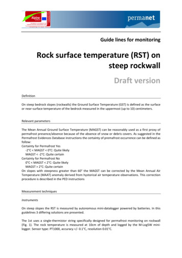
Fig. 4 – A: an M-Log5W with a temperature string with 3 nodes for a 55cm deep borehole and theUSB device for the wireless comunication. B: an iLog-3V-GPRS with the protections for the slack cablesand the support for the antenna. The protections are realized with flexible plastic hose and thermoshrink wrap.The technical specifications of both the suggested dataloggers are summarized in tables 1 and 2.Housing dimensions120 x 20 mm (cilinder)Housing specificsWaterproof stainless steelMemory capacityUp to 500.000 measure value / 2048KbData integrityNon volatile flash memoryScan cycle2 sec. to 12 hoursEnergy consumptionUp to 10 years with one batteryBattery specifics2.400 mAh / -55 C to 85 C / Li-COCl2CommunicationWireless (range up to 100 m)Operating temperature-40 C / 60 CTab. 1 – Technical specifications of the M-Log5W mini-logger.Housing dimensions175 x 80 x 55 mmHousing specificsWaterproof rugged aluminiumMemory capacityUp to 500.000 measure value / 2048KbData integrityNon volatile flash memoryScan cycle2 sec. to 12 hoursEnergy consumptionUp to 3 years (with daily GPRS transm.)Battery specifics2.400 mAh / -55 C to 85 C / Li-COCl2CommunicationGPRS and Wireless (range up to 100 m)Operating temperature-40 C / 60 CTab. 2 - Technical specifications of the iLog-3V-GPRS datalogger.
Installation procedureThe access to the installation site is usually done by abseil and the technicians must work on therope. In such conditions the tools needed for the instruments placement must be reduced to theessential and the sequence of operations must be well planned and tested before start to work onthe rope.The installation procedures described below are for the following sensor configurations:1)M-Log5W-ROCK, 1 node, measure depth: 10 cm2)M-Log5W with string, 3 nodes, measure depths: 10, 30, 55 cm3)iLog-3V-GPRS with string, 3 nodes, measure depths: 10, 30, 55 cmList of tools (Fig. 5). Cordless Driller (Suggested: Hilti TE6-A36) (1) Diamond drill bits of various diameters and lengths (2) Compressed air or hole blow out pump by hand (3) Silicon (dispenser size as toothpaste) (4) Hydraulic hose brackets for diameters of 20mm (¾ inches) (5) Wall plugs and screws (6) Screwdriver with lanyard (7) Rugged field PC (Suggested: Panasonic Toughbook-19) (8)Fig. 5 - Tools overviewStep by step installation procedures.1) M-Log5W-ROCK, 1 node, measure depth: 10 cmA - Test the positioning of the mini-logger without boreholes and brackets to see if access to thebattery is possible after installation, i.e. the backside of the logger is not obstructed.B - Drill the sensor hole with a 5 mm Ø drill bit, 10 cm deep. Pay maximum attention to the depthmeasure of the borehole.C - Remove as much dust as you can by sliding the turning drill in and out of the borehole or usingcompressed air (not ecological solution) or using an air pump by hand.
D - Insert the sensor cable fully and determine the best placement for the Logger and brackets, thenremove the sensor.E - Use the driller to mark the location of the anchoring holes.F - Drill the anchoring holes with a drill bit of the proper diameter in funtion of the hydraulic hosebrackets purchased (Fig. 5).G - Insert the sensor cable about 50 mm and then cover the hole and the rest of the cable with thesilicon. Insert the cable fully while rubbing the silicone around the hole. In this way, sealing of theborehole surface is ensured.H - Fix the logger firmly with the brackets.I - Double-check the proper sealing of the cable.J - Connect to the logger and: (1) synchronize logger clock, (2) display an instant measure, (3) checksampling parameters, (4) clear logger memory.2) M-Log5W with string, 3 nodes, measure depths: 10, 30, 55 cmFollow the steps of the first procedure with the following differences.B - Drill the sensor hole with a 10 mm Ø drill bit, 56.5 cm deep. Pay maximum attention to the depthmeasure of the borehole.C - Remove as much dust as possible by sliding the turning drill in and out of the borehole and usingcompressed air (not ecological solution) or an air pump by hand. Pay maximum attention to thiscleaning operation for these small diameter boreholes deeper than 10 cm.G - Insert the sensor cable about 50 cm and then cover the hole and the rest of the cable with thesilicon. Insert the cable fully while rubbing the silicone around the hole. In this way, sealing of theborehole surface is ensured.3) iLog-3V-GPRS with string, 3 nodes, measure depths: 10, 30, 55 cmFollow the steps of the first procedure with the following differences.A - Test the positioning of the logger and antenna without boreholes chosing a surface as regular aspossible in order to ensure a good contact of the housing base with the rock surface. Chose theposition of the sensor hole as far as possible from the logger in order to avoid disturbance due to thelogger presence.B - Drill the sensor hole with a 10 mm Ø drill bit, 56.5 cm deep. Pay maximum attention to the depthmeasure of the borehole.C - Remove as much dust as possible by sliding the turning drill in and out of the borehole and usingcompressed air (not ecological solution) or an air pump by hand. Pay maximum attention to thiscleaning operation for these small diameter boreholes deeper than 10 cm.D - Insert the sensor cable fully and double-check the best placement for the Logger and antenna.E – Remove the housing cover of the logger (put it in the backbag) and mark the location of the 2anchoring holes by a 4 mm Ø drill bit.F - Drill the 2 anchoring holes with a 5 mm Ø drill bit.G - Insert the sensor cable about 50 cm and then cover the hole and the rest of the cable with thesilicon. Insert the cable fully while rubbing the silicone around the hole. In this way, sealing of theborehole surface is ensured.H - Fix the logger firmly with the 2 screw and close the logger cover.I - Double-check the proper sealing of the cable.J - Connect to the logger and: (1) synchronize logger clock, (2) display an instant measure, (3) checksampling parameters, (4) clear logger memory.
K - Drill the anchorage hole for the antenna in function of the chosen support. Firmly fix the antennaat the rock surface.L - Fix the free cables of antenna and temperature string placing two additional hydraulic hosebrackets of proper diameter in the middle of the cable. In this way cables shaking during the stormsare avoided.Measurement strategiesThe monitoring of Rock Surface Temperature (RST) on near vertical rockwalls is performed by theapplication of mini-datalogger powered by batteries and having one or more thermistors channels.The objective of this measures is record the temperature fluctuations of a rock surface for as muchtime as possible. In high-mountain rockwalls the environmental conditions can become very hard forthe instruments mainly because the very low temperatures, strong winds and ice formation. Forthese reasons the choice of the exact location where to put the instruments and the quality of theinstallation are foundamental. This guidelines aims to give very practical suggestions for succesfullyplace dataloggers on steep slopes and get reliable dataseries of rock temperatures.At regional scale the selection of the rockwalls where put the instruments is done according to theirelevation, exposition and expected temperature, in function of our research purposes.Once identified some potential sites, the accessibility must be considered in function of:1)the budget (e.g. on foot, by cable car, helicopter and so on)2)the safety of the technicians (e.g. access/excapes routes, rock/ice falls, mobile/radiocoverage, ecc.)3)the expected number of visits per year (i.e. easy access for frequent visits)Once on site, the local placement of data loggers is of great importance. Rock faces that from afarappear to be exposed in one direction usually exhibit many individual facets of distinctly differentsteepness, exposition or local shading. The facet chosen for measurement should resemble thegeneral character of the large face as closely as possible.Measurements should only be attempted on surfaces that are homogeneous and free of visiblefractures or discontinuities within a radius of around the square of the maximum depth (i.e. 1 m ofradius for measures performed 10 cm below the surface or 2.5 m for 50 cm depths).Near-vertical situations are preferable in case the effect of snow cover wants be reduced to aminimum. On the other hand, lower slope angles likely promote formation of thin snow cover whichcan strongly affect the rock thermal regime; measures in such conditions are of particular interestsbecause scarce. In both cases, a vertical distance of several meters should be kept to the flat terrainbelow in order to avoid coverage by snow piles.Site's metadataThe following informations are the essential metadata that should be collected for each monitoringsite. The aim of these metadata is provide, to a potential unknown user, all the necessaryinformations for fully understand in which conditions were acquired the data that is watching. Thesemetadata should be compiled within an ascii file or a document or an excel sheet, this is notimportant.
1) SITESite Name (e.g. Aiguille Marbrée North)* Site Code (e.g. AM)Geographic Area (e.g. Mont Blanc)Responsible (e.g. username@gmail.com)Latitude (WGS84-dd) (e.g. 47.5426771)Longitude (WGS84-dd) (e.g. 7.8213672)* X-coordinate [system] (e.g. 5689492 [UTM ED50 zone32N])* Y-coordinate [system] (e.g. 321654 [UTM ED50 zone32N])Elevation (m) (e.g. 3500)Slope ( ) (e.g. 87)Aspect ( ) (e.g. 315)Vegetation [None, Sparse, Partly-Cov, Full-Cov] (e.g. None)Surface Type [Coarse Debris, Fine Debris, Bedrock] (e.g. Bedrock)Morphology [Slope, Ridge, Peak, Slope Base, Plateau, Depression] (e.g. Slope)2) INSTRUMENTS*Logger (e.g. M-Log6 geoprecision)Thermistor (e.g. PT1000)Accuracy [ C] (e.g. /- 0.1 C)Depth [m] (e.g. 0.03,0.3,055)Sampling frequency [s] (e.g. 600)Date Begin [dd.mm.yyyy] (e.g. 21.12.2006)(*) optionalVersion 1 – 2011 March 29th – P. Pogliotti
The 1st uses a single-thermistor string specifically designed for permafrost monitoring on rockwall (Fig. 1). The rock temperature is measured at 10cm of depth and logged by the M-Log5W mini- . The main advantage of the 3rd solution is the automatic transmission of the data by GPRS that allows .