Transcription
Communication Protocolsfor Embedded SystemsAstrit ADEMAJOverview Definition of a protocolProtocol propertiesBasic PrinciplesEmbedded system communication protocolsSummary21
What is a communication protocol?“A set of formal rules describing how to exchange data.”“Low-level protocols define the electrical and physical standards tobe observed, bit- and byte-ordering and the transmission and errordetection and correction of the bit stream.”“High-level protocols deal with the data formatting, including thesyntax of messages, the terminal to computer dialogue, charactersets, sequencing of messages etc.”3Requirements for Communication Agreed code space:How is the data encoded? Agreed time space:When is the data valid? Agreed name space:What does the transmitted data mean?42
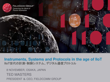
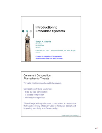
Overview Definition of a protocolProtocol propertiesBasic PrinciplesEmbedded system communication protocolsSummary5Properties of Data Exchange Message-based data exchange– Data flow– Control flow (controlling theinformation exchangebetween sender and receiver)SenderSenderfMemory Shared memory-based data exchange– No control flow over shared memoryReceiverReceiver63
State / Event Messages State messages: periodic exchange of state informationState Information : Name, Value, tobs – Time - triggered communication Event messages: sporadic exchange of event informationEvent Information : Name, ΔValue, tevent – Event - triggered communication7State Information At sender:– At-least-once transmission– Non-consuming sending, onecan send the same status datamany times. At receiver:– Update in place– Non-consuming read (one canread the last valid message) No state synchronization required IdempotentEvent Information At sender:– Exactly-once transmission– Consuming sending At receiver:– Queuing– Consumed upon read History state required queuing84
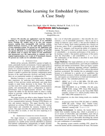
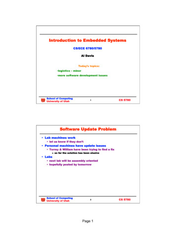
Communication Parameters Message delay– Latency - time interval between the start of message transmission at thesender node and the time of reception of the message at the receiver node– dmax maximum delay;– dmin minimum delay)– Jitter ε dmax – dmax Bandwidth– Net bandwidth vs. total bandwidth Fault handling– Message retransmission– Forward error correction– Message redundancy9Control Flow: Push and Pull Style Push style communication: Pull style communication:105
The PAR Principle(Positive Acknowledge or Retry) Sender initiates communication (Push principle)Sender waits for receivers answer or timeoutCommunication errors are detected by the senderTime redundancy is used to correct an error (increased latencyand traffic in the presence of errors) Problems:– Jitter– Thrashing (throughput decreases above particular load) PAR principle used in TCP11Message-based Clock Synchronization Simple Method – message transmission time are known:– A sends message containing its local time– Receiver B can correct with term (dmin dmax)/2– Jitter affects precision Round-Trip Method - – message transmission time are not known:– B requests timestamp message from A– B measures duration Δt until reception of answer– B corrects with term Δt/2– dmin and dmax must not be known– Jitter affects precision126
Clock Synchronization with SharedMemory Shared Memory contains a real-time image of a clock Sender must guarantee that timestamp is not older thanduration d d affects precision13Time-Triggered vs. Event-Triggered Time-triggered communication protocols– sending and receiving actions are driven by the time– exchange of state messages– All communicating partner need to have a priory knowledge of themessage send/receive time instants Event-triggered communication protocols– sending and receiving actions are driven by an event– exchange of event messages– No a priory knowledge of the message send/receive time instants isneeded147
Time-Triggered Communication Sender: Push style Receiver: Pull style Control flow is interrupted by memory elementTemporal Firewall Communication between memory element occur atpredefined instants15Time-Triggered Communication ve168
Overview Definition of a protocolProtocol propertiesBasic PrinciplesEmbedded system communication protocolsSummary17Token Principle token is passed from one station to another according to a set of rules Only the station in possession of the token is allowed to transmit data Token ring is a logical ring topology, but can physically implemented as bus,star, or ring Recovery from lost/duplicate tokens?– Token hold time– Token rotation time IEEE 802.5 (IBM token ring), FDDI (Fiber Distributed Data Interface)TMaster 1Master 2Master 3189
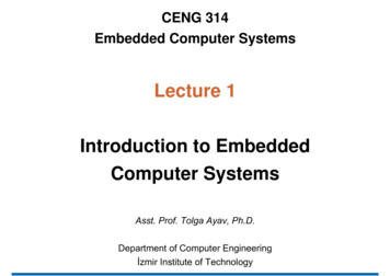
Master/Slave PrinciplePolling Master sends request message Slave answers on request Usually cyclic polling (e.g. ASi, LIN bus) Multiple masters as token ring(e.g., Profibus)TMaster 2Master 1S1S2Master 3S3S419TDMA Principle(Time Division Multiple Access) The time is the tokenRequires common time base and predefined schedule in all nodesCommon time base via distributed reference clocks (TTP/C)Common time base via master reference clock e2010
CSMA/CD Principle (Push)(Carrier Sense Multiple Access/Collision Detection) Listen before transmit. If channel is sensed busy, defertransmission Collisions may still exist, since two stations may sense thechannel idle at the same time Verify transmission by read back If collision, back off and retransmit later CSMA/CD principle used in 10Mbps Ethernet (IEEE 802.3), FastEthernet (100Mbps), Gigabit Ethernet (1,000 Mbps)21CSMA/CA Principle (Push) There are two states on the communication channel– dominant and recessive Listen before transmit. If channel is sensed busy, defertransmission Node first sends an ID and verifies bit by bit by read back Node stops transmission if a bit of the ID is overwritten by othernode ID with dominant Bits atbeginning have higher priority Requires Bit time 2 · LineDelay E.g. Bus length 40 m, propagation delay 200 nsec2211
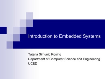
CSMA/CA Principle (Push)(Carrier Sense Multiple Access/Collision Avoidance)23Minislotting Minislotting requires that each node waits for a certain period after sending amessage before it sends another message. Media access is controlled by three intervals:– TG: Terminal Gap controlling the access to the bus, different for every node, longer than the propagation delay of the channel– TI: Transmit Interval Disabling the host from monopolizing the bus same for all nodes– SG: Synchronization Gap same for all nodesControl the sequence of entrance in the waiting roomSG max (TGi),TI SG2412
Overview Definition of a protocolProtocol propertiesBasic PrinciplesEmbedded system communication protocolsSummary25TTP/C Synchronous systemCommon communication schedule - TDMAKnown upper bound on the transmission time of a messageAerospace industryBus and/or star topologyFault tolerant– two communication channels– fault tolerant midpoint (clock synchronization)– Using a priori knowledge (guardian)2613
TTP/A Time-TriggeredTDMAMaster /SlaveBus topologyA priori knowledge27CAN protocol Event -TriggeredAutomotive industryBandwidth up to 1 Mbit/secBus topologyDifferent variants– Full CAN– CAN kingdom– 2814
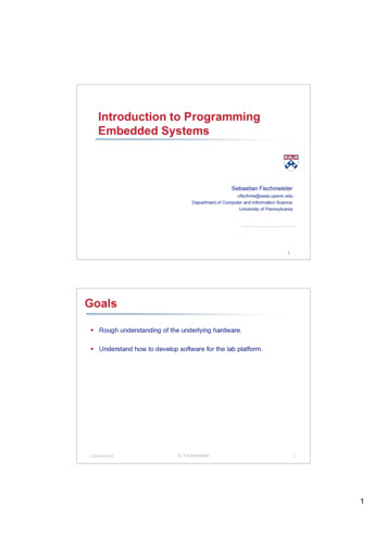
Arinc 629 Aerospace industry (Boeing 777)– Syncronization Gap (SG)– Terminal Gap (TG)– Transmitt interval (TI)Bandwidth: 2 Mbit/sec4-128 µsec0.5 – 64 msecTG1P1SGM1TG2P2TITG2SGTIM2Real Time29FlexRay Combination of TDMA and mini-slotting– Communication bandwidth is divided into two segments: Static segment (TDMA)– State messages Dynamic segment (mini-slotting)– Event messages Automotive IndustryBandwidth up to 10 Mbit/sBus or star topology3015
Time-Triggered ntrollerStandardEthernetController Integration of time-triggered andevent triggered traffic into a samecommunication infrastructure TT traffic (periodic with 16different periods) ET traffic – standard Ethernet,TCP(IP, UDP, ) Star topology Bandwidth:100 Mbit/s, 1 Gbit/s31Principle of Operation TT Ethernet switch - transmits TT msg. with a constant delay Transmission of ET msg. is preempted,– if during the transmission a TT msg. arrives at a switch port, ETmsg. is stored in the buffer of the switch, and retransmitted assoon as the transmission of the TT msg. is finished If during the transmission of TT msg. an ET msg. arrives in a portof the switch, the ET msg. is stored in the buffer of the switch andtransmitted after the transmission of TT msg. is finished3216
Overview Definition of a protocolProtocol propertiesBasic PrinciplesEmbedded system communication protocolsSummary33Conclusion Communication needs a set of rules describing how totransmit data Push style communication in combination withretransmission mechanism leads to high jitter Polling, Token ring and TDMA are deterministic Usually tradeoff: Average performance - Determinism/Worst case performance3417
Questions?3518
Arinc 629 Aerospace industry (Boeing 777) – Syncronization Gap (SG) – Terminal Gap (TG) 4-128 µsec – Transmitt interval (TI) 0.5 – 64 msec Bandwidth: 2 Mbit/sec SG SG TG1 TG2 TG2 M1 M2 TI TI Real Time P1 P2 30 FlexRay Combination of TDMA and mini-slotting – Communication bandwidth is divided into two segments: Static segment (TDMA) – State messages Dynamic .