Transcription
Preliminary Feasibility Study and Strategic PlanUniversity of ConnecticutDepot Campus, Mansfield CTMarch 31, 20121
The Connecticut Center for Advanced Technology, Inc1 (CCAT) developed this Preliminary FeasibilityStudy and Strategic Plan for the University of Connecticut’s (UConn) Depot Campus in cooperation withmany members of UConn’s faculty and staff. CCAT acknowledges the contributions of UConn’s Officeof Environmental Policy, the Center for Clean Energy Engineering, and Facilities Operations.Prepared by:Connecticut Center for Advanced Technology, Inc.222 Pitkin StreetEast Hartford, CT 06108www.ccat.us1CCAT helps private and public entities to apply innovative tools and practices to increase efficiencies, improveworkforce development and boost competitiveness. CCAT's Energy Initiative works to improve the economiccompetitiveness of the region by advancing community-supported solutions to reduce energy costs and increasereliability. As part of this goal, CCAT's Energy Initiative develops regional models for improved energy use, andhelps to foster partnerships between industry, government and academia to promote renewable energy, hydrogenand fuel cell technology.2
TABLE OF CONTENTSINTRODUCTION . 5EXECUTIVE SUMMARY . 6Depot Campus History and Building Stock .9Electric Assessment . 12Thermal Assessment . 15Education and Awareness . 18Research and Academic Interests . 18Distributed Generation (DG) and Renewable Technologies . 19Electric . 19Solar Photovoltaic Power Systems (PV) . 19Stationary Fuel Cells . 21Small Scale Wind . 23Biofuels . 24Thermal Energy . 28Ground Source Heat Pumps . 29Solar Thermal . 30Thermal Storage . 32Incentives . 33Federal Incentives . 33State Incentives . 34Implementation Targets . 35Center for Clean Energy Engineering (C2E2) - Fuel Cell . 35Center for Clean Energy Engineering (C2E2) - Demonstration PV Site . 37Longley Building - Ground Source Heat Pump . 38Thompson Building - Ground Source Heat Pump . 38Longley Building - Demonstration Wind Site . 39Longley Building - Demonstration Biofuels Site . 40Willow House - Demonstration Solar Thermal Site . 41CONCLUSION . 413
Index of FiguresFigure I -Existing Building Status . 10Figure II-Existing Building Use . 11Figure III - Depot Campus Maximum and Minimum Electric Demand (kW) . 13Figure IV - Depot Campus Maximum and Minimum Electric Demand (Amps) . 13Figure V – Annual Natural Gas Consumption for the Kennedy Cottage (2010) . 17Figure VI – Solar PV Schematic . 20Figure VII – Fuel Cell System . 21Figure VIII – Small Wind System . 23Figure IX – Geothermal Heat Pump System . 29Figure X – Solar Thermal System. 31Index of TablesTable 1- Summary of Potential Renewable Energy Applications at the Depot Campus . 7Table II – CBECS Electricity Consumption Factors . 14Table III - Estimated Electric Demand for Selected Buildings . 15Table IV - Electric Demand for C2E2 and Brown Buildings (March 2010 – March 2011) . 15Table V - Buildings with the Largest Thermal Loads (2010 Natural Gas Consumption) . 16Table VI - Buildings with the Highest Calculated Energy Intensity (Thermal) . 17Table VII - Summary of Research and Academic Interests . 18Table VIII – System Components for a Typical Small Wind Power System . 24Table IX - Electric Generating Capacity at the Depot Campus . 27Table X - Delivered Cost, Size, and Emissions for Renewable Energy Systems . 28Index of AppendicesAppendix I – Summary of Public Act 11-80 . 43Appendix II – State Incentives . 44Appendix III – Annual (2010) Natural Gas Consumption for Buildings at the Depot Campus . 494
IntroductionThe University of Connecticut (UConn) has developed this plan in support of the “Green Depot CampusInitiative”, to install, operate, and evaluate clean and renewable technologies. This initiative willfacilitate technology transfer and collaborative research into green energy sources, smart storage,reduction of carbon dioxide (CO2) and other greenhouse gases, and water management. One of the goalsof the UConn Climate Change Action Plan is to integrate environmental principles into the student’slearning experience. This initiative will also validate and demonstrate the integration of renewablegeneration systems that could exceed one megawatt (MW) of capacity, and would emulate a sustainablecommunity.The objective of the “Green Depot Campus Initiative” is to evaluate areas of the Depot Campus for selfgeneration with alternative and sustainable energy sources. This Plan includes an assessment of electricaland thermal energy consumption for the UConn buildings at the Depot Campus; analysis ofimplementation targets for energy development; and the identification of funding for projectdevelopment.This plan provides a structure for the identification and assessment of renewable and advanced energytechnologies at the Depot Campus. It is anticipated that the structure of this plan provides flexibility forupdates as new/improved technologies and opportunities for development are presented. Furthermore, thisPlan is consistent with the Preliminary Feasibility Study and Strategic Deployment Plan for Renewableand Sustainable Energy Projects, which evaluated potential deployment opportunities for renewable andsustainable energy technologies at UConn’s Storrs campuses.5
Executive SummaryThe total electric consumption for the Depot Campus is approximately 4,500,000 kilowatt hours (kWh)per year. It is estimated that are the largest consumers of electricity at the Depot Campus are the Longleybuilding, Merritt Hall, Thompson Hall, Storehouse Department of Residential Life (DRL), Brown, andthe Center for Clean Energy Engineering (C2E2) buildings. These buildings consume approximately 48percent of all electricity used at the Depot Campus. The analysis also revealed that the total thermalconsumption, which is almost exclusively fueled by natural gas is approximately 32,239,000 cubic feet or32 billion British Thermal Units (MMBtu). The buildings that are the largest consumers of natural gasand therefore thermal energy for heating/cooling and domestic hot water applications are: LongleyBuilding, Thompson Hall, Storehouse-DRL, Merritt Hall, Carpenter Shop and C2E2. The buildings onthe Depot Campus with the highest thermal energy intensity include: Norling, Hebron Cottage, theGarage/Fire House, Tolland Cottage, and Ashford Cottage. These buildings may provide the mostfavorable opportunities for conservation and advanced technologies for improved energy efficiency andreduction in greenhouse gas emissions.One of the goals of the UConn Climate Change Action Plan is to integrate environmental principles intothe student’s learning experience. In addition, increased awareness of the University’s commitment toenvironmental stewardship to minimize, to the extent practical, its impact on climate change by thestudents, staff, visitors, and the community is extremely important.Based on the estimated electricity demand, actual thermal demand, calculated energy intensity,opportunities for education and academic research, building use, and building status, the buildings thatprovide favorable opportunities for integrating renewable and advanced energy technologies in support ofthe Green Depot Campus Initiative (as shown in Table 1) include Longley Building, C2E2, Brown, andWillow House. There are also a number of buildings at the Depot Campus that have emergencygenerators and may be able to use biodiesel, a renewable fuel, for electric generation.6
Table 1- Summary of Potential Renewable Energy Applications at the Depot atedEnergy ctions ofCO2 EmissionsTotal First Cost ( )/ Lifecycle CO2EmissionsReductions ( /lb)Fuel CellCenter for CleanEnergyEngineering(C2E2)435,059 kWh/year400 kW3,250,000860,000lbs/year .33DemonstrationPV SiteCenter for CleanEnergyEngineering(C2E2) -See Above10 kW11,520 kWh/year10,575lbs/year2 .32245 tons5,414 MMBtuusing 352,500kWh to 396,600kWh3307,345lbs/year2,5 .27 to .3060,875lbs/year5 .20 to .24Ground SourceHeat PumpLongley Building6,768 MMBtus27,800 kWh to33,800 kWh4displacedGround SourceHeat PumpThompsonBuilding3,087 MMBtus40 tons1,017 MMBtuusing 66,200kWh to 74,500kWh612,000 kWh to18,000 kWhdisplaced72ISO New England, “Electric Generator Air Emissions Report – Systems Planning Department,” http://www.isone.com/genrtion resrcs/reports/emission/final 2009 emissions.pdf, 20093Based on displacing 5,414 MMBtus with a heat pump having a COP between 4.0 and 4.54Based on displacing 39,800 ton-hours of cooling with a heat pump between 4.0 and 4.5 COP5EIA, “Voluntary Reporting of Greenhouse Gases Program Fuel Emission Coefficients,” http://www.eia.gov/oiaf/1605/coefficients.html, January 31, 20116Based on displacing 1,017 MMBtus with a heat pump having a COP between 4.0 and 4.57Based on displacing 40,184 ton-hours of cooling with a heat pump having a COP between 4.0 and 4.57
Table 1- Summary of Potential Renewable Energy Applications at the Depot Campus – ions ofCO2EmissionsTotal First Cost( ) / LifecycleCO2 EmissionsReductions ( /lb)TechnologyExample Locations2010Existing/EstimatedEnergy ConsumptionWind SiteLongley Building Demonstration439,094 kWh/year10 kW5,305 kWh/year4,933 lbs/year8 .44DemonstrationBiofuels SiteLongley BuildingN/A150,000 GPY150,000 GPY16.12lbs/gallon ofB1009 0 to .0210DemonstrationSolar ThermalSiteWillow House10 MMBtus32 square feet7 MMBtus/year1024 lbs/year11 .19BiodieselElectricGenerationKennedy BuildingSurplus WarehouseChaplin CottageEllington CottageWillington CottageWillimantic CottageMerritt HallGenerator180 kW80 kW120 kW100 kW100 kW100 kW85 kW765 KW76,500kWh/year1316.12lbs/gallon ofB100 biodieselused10 0 to .0214B100126,275 GPY8ISO New England, “Electric Generator Air Emissions Report – Systems Planning Department,” http://www.isone.com/genrtion resrcs/reports/emission/final 2009 emissions.pdf, 20099Alternative PETROLEUM Technologies, “APT Fuels Clean Air at Port of Los Angeles,” LA%20present 201109a.pdf, Houlihan, Thomas, 201110Based on zero to thirty cents more per gallon for B100 as compared to #2 diesel11EIA, “Voluntary Reporting of Greenhouse Gases Program Fuel Emission Coefficients,” http://www.eia.gov/oiaf/1605/coefficients.html, January 31, 201112EIA, “ Calculators for Energy Used in the United States,” http://205.254.135.24/kids/energy.cfm?page about energy conversion calculator-basics, March201213Assumes the generator sets are used for 100 hours per year to provide backup / community area reliability14Based on zero to thirty cents more per gallon for B100 as compared to #2 diesel8
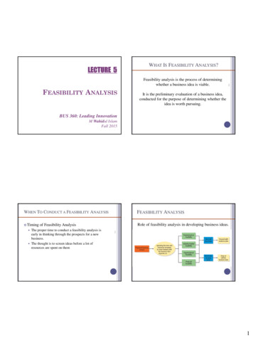
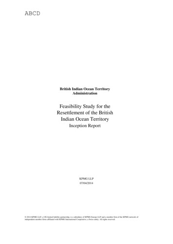
Depot Campus History and Building Stock“The Depot Campus at the University of Connecticut is located in Mansfield, Connecticut, a small townadjacent to Storrs, where the University's main campus is located. The Depot Campus was conveyed bythe Connecticut Department of Public Works to UConn in July 1993, and consists of the property andbuildings of the former Mansfield Training School. The Mansfield Training School, which was foundedin 1909, served as a multi-functional facility providing housing, educational, and medical facilities forpatients; housing and recreational facilities for employees; and a large agricultural complex providingfood for the school as well as occupational training for the patients.”15According to the University of Connecticut Depot Campus Master Plan, completed by Symmes Maini &McKee Associates in 2009, the Depot Campus contains approximately 50 buildings, with approximately714,000 gross square feet, including approximately 421,000 assignable square feet. The majority of theassignable square feet (57 percent) of all the buildings at the Depot Campus is occupied or leased, whileapproximately 43 percent consists of dead storage/vacant or storage.15University of Connecticut Depot Campus Historic Evaluation, 20099
Figure I -Existing Building Status1616University of Connecticut Depot Campus Master Plan10
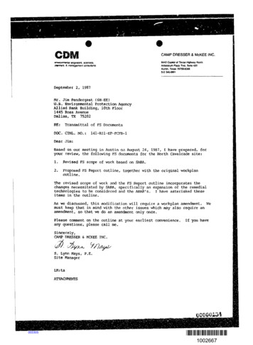
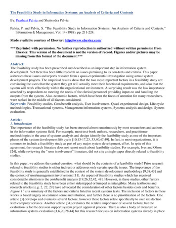
Figure II-Existing Building Use1717University of Connecticut Depot Campus Master Plan11
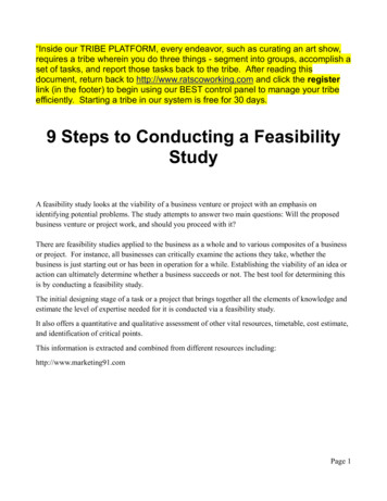
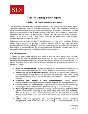
Electric AssessmentTotal electricity consumption at the Depot Campus was approximately 4,500,000 kWh/year based on ananalysis of the fifteen-minute data provided by UConn for the Depot Campus for 2010. Peak demand forthe 12 month billing period was 924 kW, with the peak demand occurring in September. A Septemberpeak most likely corresponds to the coincidence of peak occupancy levels during periods where there is aneed for cooling. Figure III and Figure IV, show the Depot Campus’s maximum and minimum electricalload at fifteen minute increments throughout the year. The figures indicate a significant spread betweenthe maximum and minimum electric demand. Net metering rules allow excess electricity produced in onepart of the day to be “banked” for use when electric consumption exceeds electric production. Excesselectricity (kWh) produced during off-peak hours and returned to the grid is credited to the customer’saccount at retail rates, provided that the annual production doesn’t exceed consumption (in this case, therenewable energy facility would receive compensation at the avoided wholesale cost of power). TheDepot Campus electric load is served through a single utility service or master meter; however, the C2E2and Brown buildings are submetered.12
11:30 AM10:45 AM10:00 AM9:15 AM8:30 AM7:45 AM7:00 AM6:15 AM5:30 AM4:45 AM4:00 AM3:15 AM2:30 AM1:45 AM1:00 AM12:15 AM13HourAmps @ 480-V; 00.011:30 PM10:45 PM10:00 PM9:15 PM11:30 PM10:45 PM10:00 PM9:15 PM8:30 PMDepot Campus Max/Min8:30 PMFigure IV - Depot Campus Maximum and Minimum Electric Demand (Amps)7:45 PM7:00 PM6:15 PM5:30 PM4:45 PM4:00 PM3:15 PM2:30 PM1:45 PM1:00 PM12:15 PM11:30 AM10:45 AM10:00 AM9:15 AM8:30 AM7:45 AM7:00 AM6:15 AM5:30 AM4:45 AM4:00 AM3:15 AM2:30 AM1:45 AM1:00 AM12:15 AMHour7:45 PM7:00 PM6:15 PM5:30 PM4:45 PM4:00 PM3:15 PM2:30 PM1:45 PM1:00 PM12:15 PMAmpskWFigure III - Depot Campus Maximum and Minimum Electric Demand (kW)Depot Campus 0.0100.00.0
The three largest energy end uses in educational facilities are: (1) lighting; (2) ventilation; and (3)cooling.18 Electricity production from a renewable energy system, such as photovoltaics (PV), fuel cells,wind, and even biofuel derived fuel gensets could provide for these end uses, and others. The DepotCampus utilizes a master meter for all the buildings that are served by electricity. This provides anexcellent opportunity to capitalize on the benefits of net metering. The disadvantage of a master meter isthat each building does not have its own electricity meter, which makes it difficult to know the exactelectric consumption for each building.The Energy Information Administration (EIA) Commercial Building Energy Consumption Survey(CBECS) can be used to estimate the electric consumption for a particular building based on its use or“principal building activity” and square footage. There are fourteen categories for the “principal buildingactivity” under the CBECS classification system. The categories that are applicable to the buildings at theDepot Campus, based on the University of Connecticut Depot Campus Master Plan that identifies thebuilding status and current use for each of the buildings at the Depot Campus (see Figure I and Figure II),includes education, office, warehouse and storage, and vacant. As detailed in Table II below, theelectricity consumption factors range from 2.4 kWh/square foot to 18.2 kWh / square foot:Table II – CBECS Electricity Consumption FactorsPer Square Foot (kWh)19,20(Zone 2)21Principal Building ActivityEducation8Office18.2Warehouse and Storage9.6Vacant2.4As detailed in Table III and Table IV below, Longley, Merritt, Thompson, Storehouse DRL, Brown, andC2E2 are estimated to be the greatest consumers of electricity at the Depot Campus.18Energy Information Administration, “Table E6. Electricity Consumption (kWh) Intensities by End Use for NonMall Buildings, tailed tables 2003/2003set19/2003pdf/e06.pdf, September 200819Energy Information Administration, “2003 Commercial Buildings Energy Consumption Survey Table ailed tables 2003/2003set10/2003excel/c20.xls, December 200620Energy Information Administration, “2003 Commercial Buildings Energy Consumption Survey Table ailed tables 2003/2003set10/2003excel/c14.xls, December 200621All of Connecticut has been designated as Climate Zone 2; Less than 2,000 CDD and 5,500 – 7,000 HDD.14
Table III - Estimated Electric Demand for Selected Buildings22BuildingNameEstimated Building mated AnnualElectricityConsumption(kWh)Percent of Total ElectricityConsumption at the DepotCampusLongley(Occupied)42,0008336,0007.5 percentLongley(Storage)42,9562.4103,0942.3 percentMerritt(Occupied)17,00018.2309,4006.4 percentMerritt(Storage)17,2562.441,4140. 9 percentStorehouseDRL27,0809.6259,9685.8 percentThompson33,8248270,5926.0 percent1,779,16239.1 percentTotals9.8 percent7.3 percent226,933Table IV - Electric Demand for C2E2 and Brown Buildings (March 2010 – March 2011)BuildingNameEstimated Building al AnnualElectricityConsumption(kWh)Percent of Total ElectricityConsumption at the DepotCampusBrown25,20316.2(Calculated)407,0599.0 percentC2E221,61420.1(Calculated)435,0599.7 percentThermal AssessmentAccording to EIA, the two largest end uses of thermal energy in educational and office facilities are forspace heating and domestic hot water applications.23 Technologies such as fuel cells, solar thermal,22Energy Information Administration, “Table E6. Electricity Consumption (kWh) Intensities by End Use for NonMall Buildings, tailed tables 2003/2003set19/2003pdf/e06.pdf, September 200815
geothermal, and biofuel derived fuel generators can provide thermal energy for both of these end uses. Asdetailed in Table V below, Longley, Thompson, Storehouse DRL, Merritt, C2E2, and Carpenter Shop arethe greatest consumers of natural gas and therefore thermal energy at the Depot Campus. Refer toAppendix III – Annual (2010) Natural Gas Consumption for Buildings at the Depot Campus for the list ofbuildings at the Depot Campus and their annual natural gas usage.Table V - Buildings with the Largest Thermal Loads (2010 Natural Gas Consumption)Building NameAnnual ThermalConsumption (CCF)Percent of TotalLongley67,68021 percentThompson30,8709.6 percentStorehouse-DRL25,5537.9 percentMerritt25,2017.8 percentC2E223,2007.2 percentCarpenter Shop15,4744.8 percent187,97858.3 percentTotalsEvaluating buildings based on total natural gas consumption is useful in identifying potential targets fordistributed generation; however, energy intensity, which is a measure of the energy consumed per area ofbuilding space used, can provide useful information to identify the best opportunities for improved energyefficiency through conservation and reduction in greenhouse gas emissions. As detailed in Table VI, thefollowing buildings on the Depot Campus have the highest energy intensity: Norling, Hebron Cottage, theGarage/Fire House, Tolland Cottage, and Ashford Cottage.23Energy Information Authority, “Table E8. Natural Gas Consumption (cubic feet) and Energy Intensities by EndUse for Non-Mail ecs2003/detailed tables 2003/2003set19/2003pdf/e08.pdf, September200816
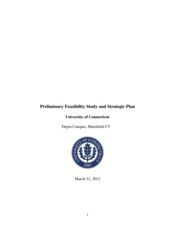
Table VI - Buildings with the Highest Calculated Energy Intensity (Thermal)24Building NameAnnual ThermalConsumption (CCF)Area(Square Feet)Energy Intensity(CCF/Square Feet)Norling10,6835,2042.05Hebron Cottage7,1703,6021.99Garage/Fire House6,9334,1721.66Tolland Cottage4,6053,6061.28Ashford Cottage329,9002,6301.25One additional factor that may be used to identify potential targets for distributed generation includesenergy utilization. The Kennedy Cottage has a natural gas demand profile which indicates that thisbuilding uses natural gas throughout the year at a level higher than other comparable buildings. Thenatural gas consumption for the Kennedy Cottage is primarily due to the natural gas fired furnace (385cubic feet/hr) and the natural gas fired chillers (375 cubic feet/hr) which provide heating or coolingthroughout the year. The annual natural gas usage for the Kennedy Cottage is depicted in Figure V,below.Figure V – Annual Natural Gas Consumption for the Kennedy Cottage (2010)Kennedy Ctg. 213190,00080,000Monthly Natural Gas Use (Cubic 24FebMarAprMayJunBased on Natural Gas Consumption for 2010.17JulAugSepOctNovDec
Education and AwarenessOne of the goals of the UConn Climate Change Action Plan is to integrate environmental principles intothe student’s learning experience. There are several buildings at the Depot Campus that may providebetter opportunities to enhance education and promote awareness. Out of the 57 buildings classified at theDepot Campus, 25 have been classified as vacant or used for storage, 11 buildings are leased, and theremaining 21 are leased to non-university entities or used to support academic interests, facilities andadministration. Those buildings that support academic interests at the Depot Campus, and are likely to bevisited by students, faculty and other members of the public include Lebanon and Colchester (fine arts),Hampton (plant science) Thompson (dramatic arts); and university related research at C2E2, Longley,Merritt, and Thompson. Buildings that are visible from Route 44, include the Brown building, which isused by administration to support human resources, Longley, and Storehouse DRL.Research and Academic InterestsThe Office of Environmental Policy at UConn recently conducted a survey to assess the research interestsof faculty at UConn. Results of this informal survey suggest that there is several opportunities to integratefaculty research interests and renewable/advanced energy technologies into plans for a “Green CampusInitiative” at the Depot campus, as detailed in Table VII below.Table VII - Summary of Research and Academic InterestsResearch Topic(s)Particular Area(s) of Interest Integration of wind/solar with conventional power generation andmicrogrid applications PV materials and devices, implementing nanotechnology in PVmaterialsWind Integration of wind/solar with conventional power generation andmicrogrid applicationsBiofuels/biomass Light-harvesting and electric potential generationphotosynthetic pigments and pigment-protein complexes Making compounds in an environmentally benign way Combustion characterization of biofuels and blending strategy withpetroleum-derived fuels Development of a gasification or methanation facilitySolar PV18by
Hydrogen/Fuel Cells Hydrogen generation by high temperature bacteriaAdvance MaterialsProcessing, Fuel Cells Long term stability, surface protection and corrosion Cell stack materials, cost reduction, stack degradation mitigationand reliability related issues in micro tubular solid oxide fuel cell(SOFC) manufacturing.Geothermal Increasing efficiency in geothermal heat exchangeEnergy/Powerconversion systems Renewable energy source integration Demonstrate osmotic heat engine Smart grid applicationsDistributed Generation (DG) and Renewable TechnologiesDG provides electricity at or near the facility where the electricity is consumed, as opposed to electricitygenerated at a remote site and transported through the electric grid via long distance transmission lines tothe facility. DG resources are typically small-scale power generation technologies in the range of 3 to10,000 kW.25 DG can be sized to cover primary power needs for critical, average and peak electric loads,and serve as resources for standby power, peak shaving and grid support. By providing multiple sourcesof electric generation in a distributed manner, the electric supply system is decentralized, potentiallyresulting in greater security and reliability. There are many technological opportunities for renewableDG, including electric generators that operate on renewable fuels such as biodiesel, fuel cells, solar PVand solar thermal, geothermal, wind or biomass. Each of these technologies has different benefits interms of installation, usage costs, best practices, fuel consumption and environmental impact.Furthermore, environmental a
Study and Strategic Plan for the University of Connecticut's (UConn) Depot Campus in cooperation with many members of UConn's faculty and staff. CCAT acknowledges the contributions of UConn's Office of Environmental Policy, the Center for Clean Energy Engineering, and Facilities Operations. Prepared by: