Transcription
LOGISIM-EVOLUTION LAB MANUALgeorge selfJuly 2019 – Edition 4.0
George Self: Logisim-Evolution Lab ManualThis work is licensed under a CreativeCommons “CC0 1.0 Universal” license.
P R E FA C EI have taught CIS 221, Digital Logic, for Cochise College since about2003 and enjoy working with students on this topic. From the start,I wanted students to work with labs as part of our studies and actually design circuits to complement our theoretical instruction. As Ievaluated circuit design software I had three criteria: Open Educational Resource (OER). It is important to me thatstudents use software that is available free of charge and is supported by the entire web community. Platform. While most of my students use a Windows-basedsystem, some use Macintosh and it was important to me touse software that is available for both of those platforms. Asa bonus, most OER software is also available for the Linux system, though I’m not aware of any of my students who are usingLinux. Simplicity. I wanted to use software that was easy to masterso students could spend their time understanding digital logicrather than learning the arcane structures of a simulation language.I originally wrote a number of lab exercises using Logisim, but thecreator of that software, Carl Burch, announced that he would quitdeveloping it in 2014. Because it was published as an open sourceproject, a group of Swiss institutes started with the Logisim softwareand developed a new version that integrated several new tools, like achronogram, and released it under the name Logisim-Evolution .It is my hope that students will find these labs instructive and thelabs enhance their learning of digital logic. This lab manual is writtenwith LATEX and published under a Creative Commons Zero licensewith a goal that other instructors can modify it to meet their ownneeds. The source code can be found at my personal GITHUB pageand I always welcome comments that will help me improve this manual.—George Selfiii
BRIEF CONTENTSList of FiguresxiList of TablesxiiiListingsxivi1introduction to logisim-evolutionintroduction to logisim-evolution13ii foundations92 boolean logic113 priority encoder21iii combinational circuits294 arithmetic logic unit (alu)315 vending machine37iv678910sequential circuitscounters47timer61reaction timer65rom67ram7545v simulation8111 processor8312 elevator95vi appendix97a ttl reference99v
CONTENTSList of FiguresxiList of TablesxiiiListingsxivi1introduction to logisim-evolutionintroduction to logisim-evolution1.1 Purpose31.2 Procedure31.2.1 Installation31.2.2 Beginner’s Tutorial31.2.3 Logisim-evolution Workspace1.2.4 Simple Multiplexer51.2.5 Identifying Information81.3 Deliverable8134ii foundations92 boolean logic112.1 Purpose112.2 Procedure112.2.1 Subcircuit: Equation 1112.2.2 Subcircuit: Equation 2132.2.3 Main Circuit142.2.4 Testing the Circuit152.3 Deliverable203 priority encoder213.1 Purpose213.2 Procedure213.2.1 Testing the Circuit273.3 Deliverable27iii combinational circuits294 arithmetic logic unit (alu)314.1 Purpose314.2 Procedure324.2.1 main324.2.2 ALU324.2.3 Arithmetic334.2.4 Challenge344.2.5 Testing the Circuit354.3 Deliverable355 vending machine375.1 Purpose37vii
viiicontents5.25.35.4Procedure375.2.1 Testing the Circuit385.2.2 Subcircuit DescriptionsChallenge43Deliverable4439iv sequential circuits456 counters476.1 Purpose476.2 Procedure476.2.1 Asynchronous Up Counter476.2.2 Asynchronous Down Counter496.2.3 Asynchronous Decade Counter506.2.4 Synchronous Ring Counter526.2.5 Synchronous Johnson Counter546.2.6 Main556.2.7 Chronogram556.3 Challenge606.4 Deliverable607 timer617.1 Purpose617.2 Procedure617.2.1 Timer V3617.2.2 Testing the Circuit627.3 Challenge637.4 Deliverable638 reaction timer658.1 Purpose658.2 Procedure658.3 Deliverable669 rom679.1 Purpose679.2 Procedure679.2.1 Testing the Circuit739.3 Deliverable7410 ram7510.1 Purpose7510.2 Procedure7510.2.1 Testing the Circuit7910.3 Challenge7910.4 Deliverable79v simulation8111 processor8311.1 Purpose8311.1.1 A Definition83
contents11.2 Procedure8311.2.1 Arithmetic-Logic Unit8311.2.2 General Registers8611.2.3 Control8711.2.4 Main8811.2.5 Testing the Circuit8811.3 About Programming Languages9111.4 Challenge9311.5 Deliverable9412 elevator9512.1 Purpose9512.2 Challenge9512.3 Deliverable96vi appendix97a ttl reference99a.1 7400: Quad 2-Input NAND Gate99a.2 7402: Quad 2-Input NOR Gate 100a.3 7404: Hex Inverter 101a.4 7408: Quad 2-Input AND Gate 102a.5 7410: Triple 3-Input NAND Gate 103a.6 7411: Triple 3-Input AND Gate 104a.7 7413: Dual 4-Input NAND Gate (Schmitt-Trigger) 105a.8 7414: Hex Inverter (Schmitt-Trigger) 106a.9 7418: Dual 4-Input NAND Gate (Schmitt-Trigger Inputs) 107a.10 7419: Hex Inverter (Schmitt-Trigger) 108a.11 7420: Dual 4-Input NAND Gate 109a.12 7421: Dual 4-Input AND Gate 110a.13 7424: Quad 2-Input NAND Gate (Schmitt-Trigger) 111a.14 7427: Triple 3-Input NOR Gate 112a.15 7430: Single 8-Input NAND Gate 113a.16 7432: Quad 2-Input OR Gate 114a.17 7436: Quad 2-Input NOR Gate 115a.18 7442: BCD to Decimal Decoder 116a.19 7443: Excess-3 to Decimal Decoder 117a.20 7444: Gray to Decimal Decoder 119a.21 7447: BCD to 7-Segment Decoder 121a.22 7451: Dual AND-OR-INVERT Gate 123a.23 7454: Four Wide AND-OR-INVERT Gate 124a.24 7458: Dual AND-OR Gate 125a.25 7464: 4-2-3-2 AND-OR-INVERT Gate 126a.26 7474: Dual D-Flipflops with Preset and Clear 127a.27 7485: 4-Bit Magnitude Comparator 128a.28 7486: Quad 2-Input XOR Gate 128a.29 74125: Quad Bus Buffer, 3-State Gate 129ix
xcontentsa.30a.31a.32a.33a.34a.3574165: 8-Bit Parallel-to-Serial Shift Register 13074175: Quad D-Flipflops with Sync Reset 13174266: Quad 2-Input XNOR Gate 13174273: Octal D-Flipflop with Clear 13274283: 4-Bit Binary Full Adder 13374377: Octal D-Flipflop with Enable 134
LIST OF FIGURESFigure 1.1Figure 1.2Figure 1.3Figure 1.4Figure 1.5Figure 1.6Figure 1.7Figure 1.8Figure 2.1Figure 2.2Figure 2.3Figure 2.4Figure 2.5Figure 2.6Figure 2.7Figure 2.8Figure 3.1Figure 3.2Figure 3.3Figure 3.4Figure 3.5Figure 3.6Figure 4.1Figure 4.2Figure 4.3Figure 4.4Figure 5.1Figure 5.2Figure 5.3Figure 5.4Figure 5.5Figure 5.6Figure 6.1Figure 6.2Figure 6.3Figure 6.4Figure 6.5Figure 6.6Figure 6.7Figure 6.8Figure 6.9Logisim-evolution Initial Screen4Two AND Gates5AND Gate Properties6OR Gate Added to Circuit6Two NOT Gates Added to Circuit7Inputs and Output Added7Circuit Wiring Added7Simple multiplexer8Equation 1 Inputs-Outputs12Equation 1 And-Or Gates12Equation 1 And Gate Inputs Set13Equation 1 Circuit Completed13Main Circuit15Test Vector Window18Test Completed19Test Failure20AND Gates22OR Gates Added23Inputs Added24Wiring the Encoder25Nine-line Priority Encoder26Main Circuit27ALU main32ALU Subcircuit33Arithmetic Subcircuit34Logic Subcircuit34Vending Machine Main Circuit39Activator Subcircuit40Bank Subcircuit40Dispenser Subcircuit41Product Subcircuit42Vending Subcircuit43Asynchronous Up Counter48Asynchronous Down Counter49Asynchronous Decade Counter51Synchronous Ring Counter53Synchronous Johnson Counter54Main Circuit55Timing Diagram for Up Counter56Set Up Chronogram57Chronogram Ready58xi
xiiList of FiguresFigure 6.10Figure 6.11Figure 6.12Figure 7.1Figure 7.2Figure 8.1Figure 9.1Figure 9.2Figure 9.3Figure 9.4Figure 9.5Figure 9.6Figure 9.7Figure 9.8Figure 9.9Figure 10.1Figure 10.2Figure 10.3Figure 10.4Figure 10.5Figure 11.1Figure 11.2Figure 11.3Figure 11.4Figure 11.5Figure 11.6Figure 12.1Figure A.1Figure A.2Figure A.3Figure A.4Figure A.5Figure A.6Figure A.7Figure A.8Figure A.9Figure A.10Figure A.11Figure A.12Figure A.13Figure A.14Figure A.15Figure A.16Figure A.17Figure A.18Figure A.19Chronogram Starting58Chronogram At Zero Time59Chronogram Controls59Completed Timer62Timer Main Circuit62Reaction Timer65Placing ROM67ROM With Counter68ROM Filter Mux69Random Generator Added70Completed Magic 8-Ball Circuit70Counter Inputs71Counter Control Generation and Distribution72ROM Output73Magic 8-Ball Main Circuit73RAM Basics75RAM With Control Signals76Data Bus77RAM With Input/Output Devices78RAM With Input/Output Devices78Simple ALU84Left Side of ALU85Full ALU85General Registers86Control Subcircuit87Main Circuit88Example Elevator Simulator96Three Surface-Mounted Integrated Circuits997400: Single NAND Gate Circuit997402: Single NOR Gate Circuit 1007404: Single Inverter Circuit 1017408: Single AND Gate Circuit 1027410: Single 3-Input NAND Gate Circuit 1037411: Single 3-Input AND Gate Circuit 1047413: Single 4-Input NAND Gate Circuit 1057414: Single Inverter Circuit 1067418: Single 4-Input NAND Gate Circuit 1077419: Single Inverter Circuit 1087420: Single 4-Input NAND Gate Circuit 1097421: Single 4-Input AND Gate Circuit 1107424: Single NAND Gate Circuit 1117411: Single 3-Input NOR Gate Circuit 1127430: Single 8-Input NAND Gate 1137432: Single OR Gate Circuit 1147436: Single NOR Gate Circuit 1157442: BCD to Decimal Decoder 116
Figure A.20Figure A.21Figure A.22Figure A.23Figure A.24Figure A.25Figure A.26Figure A.277447: BCD to 7-Segment Decoder 1217451: Single AND-OR-INVERT Gate Circuit 1237454: Four Wide AND-OR-INVERT Gate Circuit 1247458: Dual AND-OR Gate Circuit 1257464: 4-2-3-2 AND-OR-INVERT Gate Circuit 1267486: Single XOR Gate Circuit 12874125: Single Buffer Circuit 12974266: Single XNOR Gate Circuit 131L I S T O F TA B L E STable 4.1Table 6.1Table 6.2Table 6.3Table 6.4Table 6.5Table 11.1Table 11.2Table 11.3Table 11.4Table 11.5Table 11.6Table 11.7Table 11.8Table A.1Table A.2Table A.3Table A.4Table A.5Table A.6Table A.7Table A.8Table A.9Table A.10Table A.11Table A.12Table A.13Table A.14Table A.15Table A.16Table A.17Function Table for 74181 ALUUp Counter Output49Down Counter Output50Decade Counter Output52Ring Counter Output53Johnson Counter Output55R0 - LdImm88R1 - LdImm89ALU - LdImm89R0 - Inc(R0)89R0 - R0 R190R0 - R0 - R190R1 - R090R0 - R191Pinout For 7400100Pinout For 7402101Pinout For 7404102Pinout For 7408103Pinout For 7410104Pinout For 7411105Pinout For 7413106Pinout For 7414107Pinout For 7418108Pinout For 7419109Pinout For 7420110Pinout For 7421111Pinout For 7424112Pinout For 7427113Pinout For 7430114Pinout For 7432115Pinout For 743611631xiii
Table A.18Table A.19Table A.20Table A.21Table A.22Table A.23Table A.24Table A.25Table A.26Table A.27Table A.28Table A.29Table A.30Table A.31Table A.32Table A.33Table A.34Table A.35Table A.36Table A.37Table A.38Table A.39Truth Table For The 7442 CircuitPinout For 7442117Truth Table For The 7443 CircuitPinout For 7443119Truth Table For The 7444 CircuitPinout For 7444120Truth Table For The 7447 CircuitPinout For 7447123Pinout For 7451124Pinout For 7454125Pinout For 7458126Pinout For 7464127Pinout For 7474127Pinout For 7485128Pinout For 7486129Pinout For 74125130Pinout For 74165130Pinout For 74175131Pinout For 74266132Pinout For 74273133Pinout For 74283134Pinout For 74377135LISTINGSACRONYMSALUArithmetic Logic UnitBCDBinary Coded DecimalCPUCentral Processing UnitICIntegrated CircuitOEROpen Educational ResourceRAMRandom Access MemoryROMRead Only Memoryxiv117118120122
acronymsTTLTransistor-Transistor Logicxv
Part IINTRODUCTION TO LOGISIM-EVOLUTIONLogisim-Evolution is used to create and test simulations ofdigital circuits. This part of the lab manual includes onlyone lab designed to introduce Logisim-Evolution and teachthe fundamentals of using this application.
1INTRODUCTION TO LOGISIM-EVOLUTION1.1purposeThis lab introduces the Logisim-Evolution logic simulator, which isused for all lab exercises in this manual.1.2procedure1.2.1 InstallationLogisim-Evolution is a Java application, so a Java runtime environmentwill need to be installed before using the application. Many studentswho are taking a digital logic class already have a Java runtime ontheir computer and can skip this step, but those who do not will needto install the Java runtime. That process is not covered in this manual but information about installing the Java runtime environmentis available at loads/index.html. It can be confusing to know which version ofJava to download but students working on the labs in this manualonly need the runtime, called JRE on the website. Students who arealso in programming classes will likely already have the runtime aspart of the Java Developer’s Kit (JDK). It can be tricky testing theJava installation since the Chrome, Firefox, and Edge browsers willnot run Java apps, but students can open a command prompt andenter java -version to see what version of Java their computers arerunning, if any.Logisim-Evolution (https://github.com/reds-heig/logisim-evolution) is available as a free download. Visit the website and abouthalfway down the page find a section named “Running logisim-evolution.”Click the “here” link at the end of the first sentence in that section.Since the Logisim-Evolution file is a Java application, it does not needto be installed like most software. To start Logisim-Evolution , doubleclick the Logisim-Evolution shortcut. That will start Java and then runthe Logisim-Evolution application. Also, Logisim-Evolution will not needto be uninstalled when it is no longer needed since it is not actuallyinstalled, the Logisim-Evolution file can simply be deleted.1.2.2 Beginner’s TutorialLogisim-Evolution comes with a beginner’s tutorial available in Help- Tutorial. That tutorial only takes a few minutes and introduces3
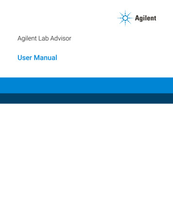
4introduction to logisim-evolutionstudents to the major components of the application. Students shouldcomplete that tutorial before starting this lab.1.2.3 Logisim-evolution WorkspaceStart Logisim-Evolution by double-clicking its icon. The initial LogisimEvolution window will be similar to Figure 1.1.Figure 1.1: Logisim-evolution Initial ScreenThe Logisim-Evolution space is divided into several areas. Along thetop is a text menu that includes the types of selections found in mostprograms. For example, the “File” menu includes items like “Save”and “Exit.” The “Edit” menu includes an “Undo” option that is useful.In later labs, the various options under “Project” and “Simulate” willbe described and used. Items in the “FPGAMenu” are beyond thescope of this class and will not be used. Of particular importanceat this point is “Library Reference” in the “Help” menu. It containsinformation about every logical device available in Logisim-Evolutionand is very useful while using those components in new circuits.Under the menu bar is the Toolbar, which is a row of eight buttonsthat are the most commonly used tools in Logisim-Evolution : Pointing Finger: Used to “poke” and change input values whilethe simulator is running.
1.2 procedure5 Arrow: Used to select components or wires in order to modify,move, or delete them. A: Activates the Text tool so text information can be added tothe circuit. Green Input Port: Creates an input port for a circuit. White Output Port: Creates an output port for a circuit. NOT Gate: Creates a NOT gate. AND Gate: Creates an AND gate. OR Gate: Creates an OR gate.The Explorer Pane is on the left side of the workspace and containsa folder list. The folders contain “libraries” of components organizedin a logical manner. For example, the “Gates” folder contains various gates (AND, OR, XOR, etc.) that can be used in a circuit. Thefour icons across the top of the Explorer Pane are used for advancedoperations and will be covered as they are needed.The Properties panel on the lower left side of the screen is wherethe properties for any selected component can be read and set. For example, the number of inputs for an AND gate can be set to a specificnumber.The drawing canvas is the largest part of the screen. It is wherecircuits are constructed and simulated.1.2.4 Simple MultiplexerA multiplexer is used to select which of two or more inputs will beconnected to a single output. For this lab, a simple two-input, onebit multiplexer will be built. It is understood that students will notknow the significance of a multiplexer at this point in the class, butthe purpose of this lab is to use Logisim-Evolution to build a simplecircuit and a multiplexer serves that purpose well.Start by clicking the And button on the toolbar and placing two ANDgates on the canvas. The canvas should resemble Figure 1.2Figure 1.2: Two AND GatesDo not be concernedwith the exactplacement ofcomponents on thedrawing canvas.They can berearranged as thebuild progresses.
6introduction to logisim-evolutionClick one of the AND gates to select it and observe the variousproperties available for that gate, as seen in Figure 1.3. The defaultvalues do not need to be changed for this circuit; however, all circuitsin this manual use the “Narrow” gate size in order to make the circuitfit the screen better. The other properties will be explained as they areneeded.Figure 1.3: AND Gate PropertiesThe outputs of the two AND gates need to be combined with an ORgate. Add an OR gate as illustrated in Figure 1.4.Figure 1.4: OR Gate Added to CircuitThe top input for the first AND gate needs two NOT gates (inverters)so the two AND gates can function as on/off switches. This is a rathercommon digital logic construct and when the circuit is complete itwill become clear how the switching function works.
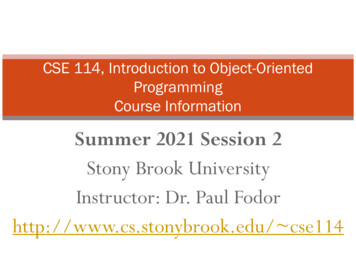
1.2 procedureFigure 1.5: Two NOT Gates Added to CircuitAll inputs and outputs need to be added as in Figure 1.6. Note:inputs are square and outputs are round. The Label property for eachinput and output should be specified as in the figure. The pins arelabeled according to their function in the circuit. Pin Sel carries asignal that selects which input to connect to the output, pins In1 andIn2 are the two inputs, and pin Out1 is the output. Note: output pinsdisplay a blue-colored X until they are actually wired to some devicelike the OR gate in the illustration.Figure 1.6: Inputs and Output AddedFinally, connect each device with a wire by clicking on the variousports and dragging a wire to the next port. To start the wire in themiddle of the two NOT gates click the wire connecting those gatesand drag downward. Wires will automatically “bend” one time butto get two bends, like between the output of an AND gate and the inputof the OR gate, click-and-drag the wire from the output of the AND gateto a spot a short distance in front of that same gate, then release themouse button and then immediately click again to start a new wirethat will “bend” to the input of the OR gate. Only a little practice isneeded to master this wiring technique.Figure 1.7: Circuit Wiring Added7
8introduction to logisim-evolutionTo operate the circuit in a simulator, click the Pointing Finger and“poke” the various inputs. If it is working properly, when the Sel input is high then the value of In2 should be transmitted to the output,but when Sel is low then the value of In1 should be transmitted to theoutput. This circuit is used to select one of two inputs to be transmitted to the output.1.2.5 Identifying InformationBefore finishing, add standard identification information near the topleft corner of the circuit using the text tool (the A button on the toolbar). That information should include the designer’s name, the labnumber and circuit name, and the date. Standard identification information for this lab would look like this:George SelfLab 01: 2-Way, 1-Bit multiplexerFebruary 13, 2018The font propertiesin Figure 1.8 havebeen set to bold anda large size to makethe text easier toread.Note that Logisim-evolution will automatically center text in a newbox, so text boxes will need to be aligned after they have been created.To align the text boxes, click the Arrow tool and use it to drag theboxes to their desired location. The completed circuit should looklike Figure 1.8.Figure 1.8: Simple multiplexer1.3deliverableThe purpose of this lab is to install and test the Logisim-evolution system and become comfortable creating a digital logic circuit.To receive a grade for this lab, create the Simple Multiplexer asdefined in this lab, be sure the standard identifying information isat the top left of the circuit, and then save the file with this name:Lab01 Mux21 (that stands for multiplexer, 2-way, 1-bit). Submit thatcircuit file for grading.
Part IIF O U N D AT I O N SFoundational Exercises are designed to provide practice with simple logic circuits in order to both developskill with Logisim-Evolution and illustrate the foundationsof digital logic.
2BOOLEAN LOGIC2.1purposeThis lab has three goals: Design circuits when given a Boolean expression. Create subcircuits. Create and exercise a test of the subcircuits.Logisim-Evolution permits designers to work with a main circuit andany number of subcircuits. Students who have studied programminglanguages are familiar with “functions” or “classes” that can be designed and built one time and then reused many times whenever theyare needed. Logisim-Evolution permits that same type of modular design by using subcircuits.The Logisim-Evolution starter for this lab includes a main circuit andone subcircuit, named Equation 1. The starter subcircuit is used topractice creating a circuit from a Boolean expression and then a newsubcircuit is added and a second Boolean expression is used to buildthat circuit.2.2procedure2.2.1 Subcircuit: Equation 1The starter circuit includes a subcircuit named Equation 1. Doubleclick that circuit in the Explorer Pane to activate it. The drawing canvas for this subcircuit is mostly blank except for a Boolean expression:(A 0 BC 0 ) (AB 0 C 0 ) (ABC). Before starting to design a circuit, it ishelpful to take a minute to analyze the expression. There are only three variables used in the entire expression: A,B, and C. Therefore, there would be three inputs into the circuit. There are three groups of variables and within each group thevariables are joined with an AND. Therefore, the circuit must include three AND gates with three inputs for each gate. The three groups of variables are joined with an OR. Therefore,the circuit must include an OR gate with three inputs.11A magnifying glassicon is used toindicate whichcircuit is active onthe drawing canvas.
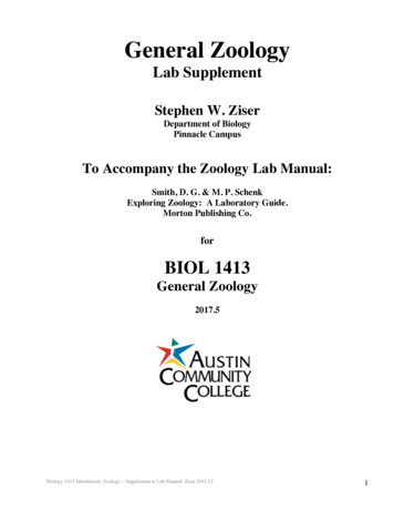
12boolean logic While the expression does not name an output variable, it isreasonable to assume that the circuit would output a logic 1 or0. Therefore, a one-bit output variable must be specified.Do not be concernedwith the exactplacement ofcomponents on thedrawing canvas.They can berearranged as thebuild progresses.Start by placing three inputs and an output on the drawing canvas.Inputs are indicated by a green icon with I- on the tool bar abovethe drawing canvas. Click that tool and place three input pins namedIn1A, In1B, and In1C —that means “Input for Equation One, variableA” and so forth.Outputs are indicated by a white icon with - O found on the toolbar above the drawing canvas. Click that tool and place an outputnamed Out1. The circuit should look like Figure 2.1.Figure 2.1: Equation 1 Inputs-OutputsThe gates in thismanual are all“narrow” size. Thesize does not changethe gate behavior butmakes it easier towire the complexcircuits in later labs.Next, the gates should be added. The AND gate tool can be foundon the tool bar. Click that tool and place three AND gates on the circuit.Click each gate and in its properties panel set the Number of Inputs to3.The OR gate tool can be found on the tool bar. Click that tool andplace one OR gate on the circuit. Click that gate and in its propertiespanel set the Number of Inputs to 3.The circuit should look like Figure 2.2.Figure 2.2: Equation 1 And-Or Gates
2.2 procedureNext, the inputs for the AND gates should be set to match the Booleanexpression. The top AND gate will match the first group of inputs,(A 0 BC 0 ), so inputs A and C should be negated. To negate those twoinputs, click the AND gate and in the properties panel set the Negateitem for the top and bottom input to “Yes.” When that is done, thetwo inputs on the AND gate should include a small “negate” circle.In the same way, the middle and bottom input for the second ANDgate should also be negated. The circuit should look like Figure 2.3.Figure 2.3: Equation 1 And Gate Inputs SetFinally, connect all gates with wires, like Figure 2.4.Figure 2.4: Equation 1 Circuit CompletedTest the circuit by selecting the poke tool in the tool bar (it looks likea pointing finger) and setting various combinations of 1 and 0 on thethree inputs. The output pin should go high only when the inputs areset to (A 0 BC 0 ), (AB 0 C 0 ), or (ABC).2.2.2Subcircuit: Equation 2A new subcircuit can be added to a circuit by clicking Project - AddCircuit. Name the new circuit Equation 2. Open the new subcircuitby double-clicking its name in the Explorer Pane.13
14boolean logicBecause this is a new subcircuit, the drawing canvas is blank. Tostart this subcircuit, write the equation for the circuit near the top ofthe drawing canvas by clicking the “A” button on the Toolbar andthen clicking near the top of the drawing canvas and typing the following:(A 0 B 0 CD 0 ) (A 0 BCD) (AB 0 CD 0 ) (ABCD 0 )It will save time to take a few minutes and analyze the expression. There are only four variables used in the entire expression: A, B,C, and D. Therefore, there would be four inputs into the circuit. There are four groups of variables and within each group thevariables are joined with an AND. Therefore, the circuit must include four AND gates with four inputs for each gate. The four groups of variables are joined with an OR. Therefore,the circuit must include an OR gate with four inputs. While the expression does not name an output variable, it isreasonable to assume that the circuit would output a logic 1 or0. Therefore, a one-bit output variable must be specified.Design the subcircuit using these names for the inputs: In2A, In2B,In2C, and In2D. Also include an output named Out2. Set the AND gatesso the their inputs are negated properly and then wire the entiresubcircuit. Finally, test the circuit to ensure the output goes high onlywhen the four specified combinations of inputs are present.2.2.3 Main CircuitMake the main circuit active by double-clicking its name in the Explorer Panel. Click once on the Equation 1 circuit and the cursor willchange into an image of that circuit as it will appear on the drawing canvas. Click on the drawing canvas to drop that subcircuit. Thecircuit can later be moved by clicking it and dragging it to a new location. Wire the three inputs and output as shown in Figure 2.5. Noticethat the input/output pins do not need to be named the same as inthe subcircuit; for example, the output for Equation 1 is labeled Out1but it is connected to an output pin labeled True1.
2.2 procedure15Figure 2.5: Main CircuitAdd the Equation 2 circuit in the same way and wire four inputsand one output to that circuit. The inputs should be labeled A2, B2,C2, and D2 and the output labeled True2.2.2.4Testing the CircuitOne way to test this circuit is to use the poke tool and click variousinput combinations for both subcircuits. If the subcircuits are correctthen the output will only go high when the correct combination is seton the inputs. However, as digital logic circuits become more complexit is important to automate the testing process so no input combinations are overlooked. Logisim-Evolution includes a Simulate - TestVector feature that is used for automating circuit testing.The first step in using automatic testing is to create a Test Vector file.This is a simple .txt file that can be created in any text processor, likeNotepad. The format for a test vector is fairly simple. Every line is a single test of the circuit, except the first line. The first line defines the various inputs and outputs being tested. Any line that starts with a hash mark (#) is a comment and isignored.Following is the test vector file used to test the Equation 1 subcircuit.1# Test vector for Lab 22# Equation 13A1 B1 C1 True1400005001060101701108100191010101100111111Do not use a wordprocessor to createthe Test Vector sincethat would addunneeded codes forthings like fonts andmargins.
16boolean logicFollowing is an explanation for the Test vector for Lab 2 file.line 1 This is just the title of the file. Because this line starts with ahash (#) it is a comment and will be ignored by Logisim-Evolution.line 2 This is another descriptor line and is ignored by LogisimEvolution .line 3 This line lists all of the inputs and outputs in the circuit undertest. In this case, there are three inputs, A1, B1, and C1, alongwith one output, True1. Logisim-Evolution is able to determinewhether the pin is an input or output from its properties. NOTE:each of the inputs and outputs in this circuit are single bits. Ifan input or output has more than one bit then that must bespecified on this line. For example, if True1 was actually a fourbit output then that pin would be listed as True1[4].line 4 This line contains the first test for the circuit. This line specifies that Logisim-Evolution make A1, B1, and C1 equal to zeroand then check to be certain that True1 is also zero.other lines All other lines set the three input bits and specify theexpected response in the output bit.The test vector for Equation 2 would look like this:1# Test vector for Lab 22# Equation 23A2 B2 C2 D2 11011911110
2.2 procedureIn practice, a circuit designer would usually not create two differenttest vectors but would, instead, create just one file to test all parts ofthe circuit. Combining the Equation 1 test and the Equation 2 test isnot quite as easy as appending one after the other since all inputand output pins for both circuits must be specified at the top of thefile. Following is the test vector for a circuit that combines Equation1 and Equation 2. Notice that all input and output pins are definedon line three then each line beginning with line four tests both of theequation circuits. Because only eight te
1.2.3 Logisim-evolution Workspace 4 1.2.4 Simple Multiplexer 5 1.2.5 Identifying Information 8 1.3 Deliverable 8 ii foundations9 2 boolean logic11 2.1 Purpose 11 2.2 Procedure 11 2.2.1 Subcircuit: Equation 111 2.2.2 Subcircuit: Equation 213 2.2.3 Main Circuit 14 2.2.4 Testing the Circuit 15 2.3 Deliverable 20 3 priority encoder21 3.1 Purpose 21 .