Transcription
Headed Bar and MechanicalAnchor Design Aid
ContentINTRODUCTION. 3EXAMPLE A1: Replacing a standard hook with #11 Grade 60 or Grade 80 rebar . 4EXAMPLE A2: Single anchor with #14 Grade 60 rebar . 10EXAMPLE A3: Single anchor with #18 Grade 60 rebar . 14Example B1, Group of anchors with #11 Grade 80 rebar . 18Example B2, Group of anchors with #14 Grade 60 rebar (close proximity to an edge). 27Appendix A: Development Length Tables (standard hooks and headed reinforcing bars) . 40Appendix B: Solving for hef . 41Appendix C: Additional Information (references to supplementary resources and literature) . 43Appendix D: Frequently Asked Questions . 46Appendix E: Application Pictures . 51nVent.com/LENTON 2
INTRODUCTIONThe nVent LENTON Headed Bar and Mechanical Anchor Design Aid is provided to facilitatedesigning reinforcing bar anchorage with the nVent LENTON Terminator and nVentLENTON Ultimate headed bar anchor systems.Since the issuing of ACI 318-08, relevant sections of ACI 318 have been utilized to provideguidance on designing with headed deformed bars to ensure that the effective embedmentin concrete is sufficient to develop the necessary force in the reinforcing bar, refer toSection 25.4.4 of ACI 318-14 (12.6 of ACI 318-11). However, when criteria in Section25.4.4.1 of ACI 318-14 (12.6.1 of ACI 318-11) is not met, a widespread unfamiliarity existsregarding acceptable methods for performing design calculations. This design aid providesvarious example calculations for headed reinforcing bar following Chapter 17 of ACI 318-14(Appendix D of ACI 318-11). In each design example, the following failure modes areevaluated:1. Concrete breakout strength in tension (Ncb), Section 17.4.2 of ACI 318-14(D.5.2 of ACI 318-11).2. Pullout strength in tension (Npn), Section 17.4.3 of ACI 318-14 (D.5.3 ofACI 318-11).3. Concrete side-face blowout strength in tension (Nsb), Section 17.4.4 ofACI 318-14 (D.5.4 of ACI 318-11).The nVent LENTON Headed Bar and Mechanical Anchor Design Aid examples are intendedto be used for reference only. The Engineer of Record shall ensure that calculations anddesigns are performed properly for the corresponding applicationsand requirements.nVent.com/LENTON 3
EXAMPLE A1: Replacing a standard hook with a single anchor of #11Grade 60 or Grade 80 rebarThe initial design for a connection between two cast-in-place concrete members callsfor a standard hook with #11 ASTM A615 Grade 60 rebar in normalweight concrete witha compressive strength ( f c’ ) of 4,000 psi. According to Section 25.4.3 of ACI 318-14(12.5 of ACI 318-11), the minimum development length of the hook is 26.8 inches. Dueto the need to develop the required strength in a shorter length, the hook is thenreplaced with a mechanical anchor. As all conditions of Section 25.4.4.1 of ACI 318-14(12.6.1 of ACI 318-11) are met, the development length is calculated by the followingequation from Section 25.4.4.2 of ACI 318-14 (12.6.2 of ACI 318-11):𝑙𝑙𝑑𝑑𝑑𝑑 0.016𝑓𝑓𝑦𝑦 ψ𝑒𝑒 𝑓𝑓′𝑐𝑐SymbolValueUnitACI 318-14ACI 318-11fy60,000psi-- 𝑑𝑑𝑏𝑏DescriptionSpecified yield strength of the reinforcing bar.1.0-25.4.4.312.6.2Modification factor for development length,based on coating, 1.0 for black bar, 1.2 forepoxy coated.f ’c4,000psi--Specified compressive strength of concrete.db1.41in--Nominal diameter of reinforcing bar.ψe𝑙𝑙𝑑𝑑𝑑𝑑 lbf (1.0)in2 (1.41 in)lbf 4,000 2 in0.016 60,000𝑙𝑙𝑑𝑑𝑑𝑑 21.4 inFor this particular scenario, the development length is determined to be 21.4 inches,which is approximately 80% of the required development length for a hooked bar underequal circumstances. For reference, the tables below contain development lengthcharts for hooked and headed bars according to the calculation methods from thereferenced sections of ACI 318.nVent.com/LENTON 4
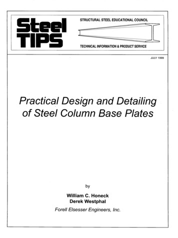
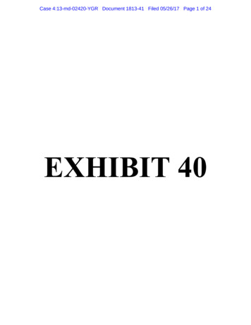
The design is then modified to use ASTM A706 Grade 80 rebar, rather than ASTM A615Grade 60. As the use of Grade 80 rebar does not comply to condition (b) of Section25.4.4.1 of ACI 318-14 (12.6.1 of ACI 318-11), Chapter 17 of ACI 318-14 (Appendix D ofACI 318-11) may be used to perform the necessary design calculations on the headedreinforcing bar, treating it as an anchor.Evaluating the headed rebarto Chapter 17 of ACI 318-14(Appendix D of ACI 318-11)enables the calculation ofconcrete breakout strength intension (Ncb), pullout strengthin tension (Npn), and concreteside-face blowout strength intension (Nsb) to ensure thatthe designed performancemeets the factored tensileforce (Nua), which in this example is 124,800 lbf (80,000 psi x 1.56 in2).Concrete Breakout Strength in Tension (Ncb) and Effective Embedment Depth (hef):Breakout strength in tension can be calculated with the provided equations in Section17.4.2 of ACI 318-14 (D.5.2 of ACI 318-11). However, for design purposes, the variablefor effective embedment depth (hef) is solved for from the relevant equations. As shownin the equation below, hef is the required embedment to provide adequate breakoutstrength for the selected factored design strength. See Appendix B, Solving for hef in thisdesign aid for the derivation of the equation shown below.nVent.com/LENTON 5
2/3𝑁𝑁𝑢𝑢𝑢𝑢ℎ𝑒𝑒𝑒𝑒 𝐴𝐴𝑁𝑁𝑁𝑁φψψ ψ𝑘𝑘 𝜆𝜆𝐴𝐴𝑁𝑁𝑁𝑁𝑁𝑁 𝑒𝑒𝑒𝑒,𝑁𝑁 𝑐𝑐,𝑁𝑁 𝑐𝑐𝑐𝑐,𝑁𝑁 𝑐𝑐 𝑎𝑎 𝑓𝑓′𝑐𝑐SymbolValueUnitACI 318-14ACI 318-11Nua124,800lbf--DescriptionFactored tensile force applied to an anchor.Strength reduction factor for anchorsgoverned by concrete breakout, whensupplementary reinforcement is not present(Condition B).Actual projected failure area (ANc ) divided bytheoretical projected failure area (ANco), setequal to 1.0 for a single anchor away 4.2.1RD.5.2.1ψed,N1.0-17.4.2.5D.5.2.5Modification factor for edge proximity, whennot affected by edge, set equal to 1.0.ψc,N1.25-17.4.2.6D.5.2.6Modification factor based on presence orabsence of cracks, 1.25 for no cracks.ψcp,N1.0-17.4.2.7D.5.2.7Modification factor for post-installedanchors, set equal to 1.0 for cast-in 0psi--f ’cℎ𝑒𝑒𝑒𝑒 Coefficient for basic concrete breakoutstrength in tension.Modification factor for lightweight concrete,normalweight 1.0.Specified compressive strength of concrete.124,800 lbf(0.70)(1.0)(1.0)(1.25)(1.0)(24)(1.0) 4,000 psi 2/3ℎ𝑒𝑒𝑒𝑒 20.7 innVent.com/LENTON 6
Alternate Equation for Concrete Breakout Strength (Ncb) and Effective EmbedmentDepth (hef):If the effective embedment depth (hef) is greater than or equal to 11 inches and lessthan or equal to 25 inches, the equation previously used in this example (whose rootequation is found in Section 17.4.2.2a of ACI 318-14 (equation D-6 of ACI 318-11)) canbe too conservative in certain cases, see comments in Section R17.4.2.2 of ACI 318-14(RD.5.2.2 of ACI 318-11). For this reason, the alternate equation is provided in 17.4.2.2bof ACI 318-14 (Equation D-7 of ACI 318-11). The alternate effective embedment depth(hef) is then calculated with the equation below (refer to Appendix B in this design aidfor its derivation), where all variables remain the same as shown in the prior calculation,except that the value for kc of 24 is replaced with 16, per Section 17.4.2.2b of ACI 31814 (D-7 of ACI 𝑒 𝐴𝐴𝑁𝑁𝑁𝑁φψψ ψ𝑘𝑘 16𝜆𝜆𝑎𝑎 � 𝑒𝑒𝑒𝑒,𝑁𝑁 𝑐𝑐,𝑁𝑁 𝑐𝑐𝑐𝑐,𝑁𝑁 𝑐𝑐ℎ𝑒𝑒𝑒𝑒 124,800 lbf(0.70)(1.0)(1.0)(1.25)(1.0)(16)(1.0) 4,000 psi 3/5ℎ𝑒𝑒𝑒𝑒 19.5 inNote that even with a higher strength rebar (fy of 80,000 psi), the calculations based onChapter 17 of ACI 318-14 (12.6 of ACI 318-11) result in shorter effective embedmentdepths (20.7 inches and 19.5 inches) compared to the development length of 21.4inches calculated according to Section 25.4.4.2 of AC I 318-14 (12.6.2 of ACI 318-11)with rebar at 60,000 psi fy. Under certain conditions, such as single anchors locatedaway from edges, calculating the effective embedment depth to Chapter 17 of ACI 31814 (Appendix D of ACI 318-11) may result in shorter effective embedment depths.However, it must be understood that changes to the variables (fy, Nua, f ’c , spacing, clearcover, etc.) will have varying impacts on the calculated results. Using Chapter 17 of ACI318-14 (Appendix D of ACI 318-11) may result in a shorter effective embedment depthunder a particular set of conditions, but not under a separate set of conditions.Therefore, evaluating to both calculation methods (when applicable), can be a wisepractice for design optimization.nVent.com/LENTON 7
Pullout Strength of Cast-in Anchor in Tension (Npn): The nominal pullout strength of asingle cast-in anchor (Npn) can be calculated from the equations found in Section 17.4.3of ACI 318-14 (D.5.3 of ACI 318-11) by substituting for Np (pullout strength of a singleanchor in cracked concrete), as shown below. Note that Npn is representative of the loadat which initial crushing of the concrete occurs, not the load required to pull the anchorout of the concrete entirely, reference Section R17.4.3.4 of ACI 318-14 (RD.5.3.4 of ACI318-11).SymbolValueUnitACI 318-14ACI ation factor based on presence orabsence of cracks, set equal to 1.4 for nocracks, 1.0 for cracking at service load levels.Abrg6.74in2--Net bearing area of EL36D6 Terminator.f ’c4,000psi--Specified compressive strength of concrete.𝑁𝑁𝑝𝑝𝑝𝑝 (1.4)(8)(6.74 in2 )(4,000 psi)𝑁𝑁𝑝𝑝𝑝𝑝 301,952 lbfEven when the strength reduction factor (φ) of 0.70 is multiplied by Npn, the result is stillwell above the factored tensile load applied to the anchor (Nua), which, in this example is124,800 lbf. Reference Sections 17.3.3 of ACI 318-14 (D.4.3 of ACI 318-11) and 17.3.1.1of ACI 318-14 (D4.1.1 of ACI 318-11).φ𝑁𝑁𝑝𝑝𝑝𝑝 𝑁𝑁𝑢𝑢𝑢𝑢(0.70)(301,952 lbf) 124,800 lbf211,366 lbf 124,800 lbfnVent.com/LENTON 8
Side-Face Blowout Strength of a Headed Anchor in Tension (Nsb): For anchors with theeffective embedment depth (hef) greater than 2.5(ca1), where ca1 is the distance fromthe center of the anchor to the nearest edge, the side-face blowout strength of a headedanchor in tension can be determined from Section 17.4.4 of ACI 318-14 (D.5.4 of ACI318-11). As 2.5(ca1) is greater than hef in this example, Nsb need not be considered.Summary: hef for the ASTM A706 Grade 80 #11 rebar embedded in normalweight 4,000 psiconcrete is calculated to be 19.5 in, based on a factored design strength (Nua) of 124,800 lbf.φNpn Nua (211,366 lbf 124,800 lbf).Evaluation of the side-face blowout strength (Nsb) is not required.nVent.com/LENTON 9
EXAMPLE A2: Single anchor with #14 Grade 60 rebarAn engineer has designed for a single nVent LENTON Terminator EL43TD6 positionedaway from all edges to be used with uncoated #14 ASTM A615 Grade 60 rebar innormalweight concrete with a compressive strength (f ’c ) of 4,000 psi. As the use of #14rebar does not comply to condition (c) of Section 25.4.4.2 of ACI 318-14 (12.6.1 of ACI318-11), Chapter 17 of ACI 318-14 (Appendix D of ACI 318-11) may be utilized fordesign purposes. Note that Section 17.3.2.2 of ACI 318-14 (D.4.2.2 of ACI 318-11) permitsuse of anchor diameters up to 4 inches.Evaluating the headed rebar to Chapter 17 of ACI 318-14 (Appendix D of ACI 318-11)enables the calculation of concrete breakout strength in tension (Ncb), pullout strengthin tension (Npn), and concrete side-face blowout strength in tension (Nsb) to ensure thatthe designed performance meets the factored tensile force (Nua), which in this case is135,000 lbf.Concrete Breakout Strength in Tension (Ncb) and Effective Embedment Depth (hef):Breakout strength in tension can be calculated with the provided equations in Section17.4.2 of ACI 318-14 (D.5.2 of ACI 318-11). However, for design purposes, the variablefor effective embedment depth (hef) is solved for from the relevant equations. SeeAppendix B, Solving for hef in this design aid for the derivation of the equation shownbelow.nVent.com/LENTON 10
2/3𝑁𝑁𝑢𝑢𝑢𝑢ℎ𝑒𝑒𝑒𝑒 𝐴𝐴φ 𝑁𝑁𝑁𝑁 ψ𝑒𝑒𝑒𝑒,𝑁𝑁 ψ𝑐𝑐,𝑁𝑁 ψ𝑐𝑐𝑐𝑐,𝑁𝑁 𝑘𝑘𝑐𝑐 𝜆𝜆𝑎𝑎 �SymbolValueUnitACI 318-14ACI 318-11Nua135,000lbf--Factored tensile force applied to an anchor.D.4.3(c)Strength reduction factor for anchorsgoverned by concrete breakout, whensupplementary reinforcement is not present(Condition ctual projected failure area (ANc) divided bytheoretical projected failure area (ANco), setequal to 1.0 for a single anchor away fromedges.ψed,N1.0-17.4.2.5D.5.2.5Modification factor for edge proximity, whennot affected by edge, set equal to 1.0.ψc,N1.25-17.4.2.6D.5.2.6Modification factor based on presence orabsence of cracks, 1.25 for no cracks.ψcp,N1.0-17.4.2.7D.5.2.7Modification factor for post-installedanchors, set equal to 1.0 for cast-in anchors.kc24-17.4.2.2D.5.2.2Coefficient for basic concrete breakoutstrength in tension.λa1.0-17.2.6D.3.6Modification factor for lightweight concrete,normalweight 1.0.4,000psi--Specified compressive strength of concrete.f ’cℎ𝑒𝑒𝑒𝑒 -17.3.3(c)135,000 lbf (0.70)(1.0)(1.0)(1.25)(1.0)(24)(1.0) 4,000 psi2/3ℎ𝑒𝑒𝑒𝑒 21.8 innVent.com/LENTON 11
Alternate Equation for Concrete Breakout Strength (Ncb) and Effective EmbedmentDepth (hef):If the effective embedment depth (hef) is greater than or equal to 11 inches and lessthan or equal to 25 inches, the equation previously used in this example, (whose rootequation is found in Section 17.4.2.2a of ACI 318-14 (equation D-6 of ACI 318-11)) canbe too conservative in certain cases, see comments in Section R17.4.2.2 of ACI 318-14(RD.5.2.2 of ACI 318-11). For this reason, the alternate equation is provided in 17.4.2.2bof ACI 318-14 (Equation D-7 of ACI 318-11). The alternate effective embedment depth(hef) is then calculated with the equation below (refer to Appendix B in this design aidfor its derivation), where all variables remain the same as shown in the prior calculation,except that the value for kc of 24 is replaced with 16, per Section 17.4.2.2b of ACI 31814 (D-7 of ACI 𝑒 𝐴𝐴𝑁𝑁𝑁𝑁φψψ ψ𝑘𝑘 16𝜆𝜆𝑎𝑎 � 𝑒𝑒𝑒𝑒,𝑁𝑁 𝑐𝑐,𝑁𝑁 𝑐𝑐𝑐𝑐,𝑁𝑁 𝑐𝑐ℎ𝑒𝑒𝑒𝑒 135,000 lbf (0.70)(1.0)(1.0)(1.25)(1.0)(16)(1.0) 4,000 psi3/5ℎ𝑒𝑒𝑒𝑒 20.4 inPullout Strength of Cast-in Anchor in Tension (Npn): The nominal pullout strength of asingle cast-in anchor (Npn) can be calculated from the equations found in Section 17.4.3of ACI 318-14 (D.5.3 of ACI 318-11) by substituting for Np (pullout strength of a singleanchor in cracked concrete), as shown below. Note that Npn is representative of the loadat which initial crushing of the concrete occurs, not the load required to pull the anchorout of the concrete entirely, reference Section R17.4.3.4 of ACI 318-14 (RD.5.3.4 of ACI318-11).nVent.com/LENTON 12
SymbolValueUnitACI 318-14ACI ation factor based on presence or absenceof cracks, set equal to 1.4 for no cracks, 1.0 forcracking at service load levels.Abrg10.316in2--Net bearing area of EL43TD6 Terminator.f ’c4,000psi--Specified compressive strength of concrete.𝑁𝑁𝑝𝑝𝑝𝑝 (1.4)(8)(10.316 in2 )(4,000 psi)𝑁𝑁𝑝𝑝𝑝𝑝 462,157 lbfEven when the strength reduction factor (φ) of 0.70 is multiplied by Npn, the result is stillwell above the factored tensile load applied to the anchor (Nua). Reference Sections17.3.3 of ACI 318-14 (D.4.3 of ACI 318-11) and 17.3.1.1 of ACI 318-14 (D4.1.1 of ACI318-11).φ𝑁𝑁𝑝𝑝𝑝𝑝 𝑁𝑁𝑢𝑢𝑢𝑢(0.70)(462,157 lbf) 135,000 lbf323,510 lbf 135,000 lbfSide-Face Blowout Strength of a Headed Anchor in Tension (Nsb): For anchors with aneffective embedment depth (hef) greater than 2.5(ca1), where ca1 is the distance from thecenter of the anchor to the nearest edge, the side-face blowout strength of a headedanchor in tension can be determined from Section 17.4.4 of ACI 318-14 (D.5.4 of ACI318-11). As 2.5(ca1) is greater than hef in this example, Nsb need not be considered.Summary: hef for the ASTM A615 Grade 60 #14 rebar embedded in normalweight 4,000 psiconcrete is calculated to be 20.4 in, based on a factored design strength (Nua) of135,000 lbf. φNpn Nua (323,510 lbf 135,000 lbf). Evaluation of the side-face blowout strength (Nsb) is not required.nVent.com/LENTON 13
EXAMPLE A3: Single anchor with #18 Grade 60 rebarAn engineer has designed for a single nVent LENTON Terminator EL57TD6 positionedaway from all edges to be used with uncoated #18 ASTM A615 Grade 60 rebar innormalweight concrete with a compressive strength (f ’c) of 4,000 psi. As the use of #18rebar does not comply to condition (c) of Section 25.4.4.2 of ACI 318-14 (12.6.1 of ACI318-11), Chapter 17 of ACI 318-14 (Appendix D of ACI 318-11) may be utilized fordesign purposes. Note that Section 17.3.2.2 of ACI 318-14 (D.4.2.2 of ACI 318-11) permitsuse of anchor diameters up to 4 inches.Evaluating the headed rebar to Chapter 17 of ACI 318-14 (Appendix D of ACI 318-11)enables the calculation of concrete breakout strength in tension (Ncb), pullout strengthin tension (Npn), and concrete side-face blowout strength in tension (Nsb) to ensure thatthe designed performance meets the factored tensile force (Nua), which in this case is240,000 lbf.Concrete Breakout Strength in Tension (Ncb) and Effective Embedment Depth (hef):Breakout strength in tension can be calculated with the provided equations in Section17.4.2 of ACI 318-14 (D.5.2 of ACI 318-11). However, for design purposes, the variablefor effective embedment depth (hef) is solved for from the relevant equations. SeeAppendix B, Solving for hef in this design aid for the derivation of the equation shownbelow.nVent.com/LENTON 14
2/3𝑁𝑁𝑢𝑢𝑢𝑢ℎ𝑒𝑒𝑒𝑒 𝐴𝐴φ 𝑁𝑁𝑁𝑁 ψ𝑒𝑒𝑒𝑒,𝑁𝑁 ψ𝑐𝑐,𝑁𝑁 ψ𝑐𝑐𝑐𝑐,𝑁𝑁 𝑘𝑘𝑐𝑐 𝜆𝜆𝑎𝑎 �SymbolValueUnitACI 318-14ACI 318-11Nua240,000lbf--Factored tensile force applied to an anchor.D.4.3(c)Strength reduction factor for anchorsgoverned by concrete breakout, whensupplementary reinforcement is not present(Condition ctual projected failure area (ANc) divided bytheoretical projected failure area (ANco), setequal to 1.0 for a single anchor away fromedges.ψed,N1.0-17.4.2.5D.5.2.5Modification factor for edge proximity, whennot affected by edge, set equal to 1.0.ψc,N1.25-17.4.2.6D.5.2.6Modification factor based on presence orabsence of cracks, 1.25 for no cracks.ψcp,N1.0-17.4.2.7D.5.2.7Modification factor for post-installedanchors, set equal to 1.0 for cast-in 0psi--f ’cℎ𝑒𝑒𝑒𝑒 -17.3.3(c)Coefficient for basic concrete breakoutstrength in tension.Modification factor for lightweight concrete,normalweight 1.0.Specified compressive strength of concrete.240,000 lbf (0.70)(1.0)(1.0)(1.25)(1.0)(24)(1.0) 4,000 psi2/3ℎ𝑒𝑒𝑒𝑒 32.0 innVent.com/LENTON 15
Alternate Equation for Concrete Breakout Strength (Ncb) and Effective EmbedmentDepth (hef):If the effective embedment depth (hef) is greater than or equal to 11 inches and lessthan or equal to 25 inches, the equation previously used in this example, (whose rootequation is found in Section 17.4.2.2a of ACI 318-14 (equation D-6 of ACI 318-11)) canbe too conservative in certain cases, see comments in Section R17.4.2.2 of ACI 318-14(RD.5.2.2 of ACI 318-11). For this reason, the alternate equation is provided in 17.4.2.2bof ACI 318-14 (Equation D-7 of ACI 318-11). The alternate effective embedment depth(hef) is then calculated with the equation below (refer to Appendix B in this design aidfor its derivation), where all variables remain the same as shown in the prior calculation,except that the value for kc of 24 is replaced with 16, per Section 17.4.2.2b of ACI 31814 (D-7 of ACI 𝑒 𝐴𝐴φ 𝑁𝑁𝑁𝑁 ψ𝑒𝑒𝑒𝑒,𝑁𝑁 ψ𝑐𝑐,𝑁𝑁 ψ𝑐𝑐𝑐𝑐,𝑁𝑁 𝑘𝑘𝑐𝑐 16𝜆𝜆𝑎𝑎 �ℎ𝑒𝑒𝑒𝑒 240,000 lbf (0.70)(1.0)(1.0)(1.25)(1.0)(16)(1.0) 4,000 psi3/5ℎ𝑒𝑒𝑒𝑒 28.8 inPullout Strength of Cast-in Anchor in Tension (Npn): The nominal pullout strength of asingle cast-in anchor (Npn) can be calculated from the equations found in Section 17.4.3of ACI 318-14 (D.5.3 of ACI 318-11) by substituting for Np (pullout strength of a singleanchor in cracked concrete), as shown below. Note that Npn is representative of the loadat which initial crushing of the concrete occurs, not the load required to pull the anchorout of the concrete entirely, reference Section R17.4.3.4 of ACI 318-14 (RD.5.3.4 of ACI318-11).nVent.com/LENTON 16
SymbolValueUnitACI 318-14ACI ation factor based on presence or absenceof cracks, set equal to 1.4 for no cracks, 1.0 forcracking at service load levels.Abrg16.669in2--Net bearing area of EL57TD6 Terminator.f ’c4,000psi--Specified compressive strength of concrete.𝑁𝑁𝑝𝑝𝑝𝑝 (1.4)(8)(16.669 in2 )(4,000 psi)𝑁𝑁𝑝𝑝𝑝𝑝 746,771 lbfEven when the strength reduction factor (φ) of 0.70 is multiplied by Npn, the result is stillwell above the factored tensile load applied to the anchor (Nua). Reference Sections17.3.3 of ACI 318-14 (D.4.3 of ACI 318-11) and 17.3.1.1 of ACI 318-14 (D4.1.1 of ACI318-11).φ𝑁𝑁𝑝𝑝𝑝𝑝 𝑁𝑁𝑢𝑢𝑢𝑢(0.70)(746,771 lbf) 240,000 lbf522,740 lbf 240,000 lbfSide-Face Blowout Strength of a Headed Anchor in Tension (Nsb): For anchors with aneffective embedment depth (hef) greater than 2.5(ca1), where ca1 is the distance from thecenter of the anchor to the nearest edge, the side-face blowout strength of a headedanchor in tension can be determined from Section 17.4.4 of ACI 318-14 (D.5.4 of ACI318-11). As 2.5(ca1) is greater than hef in this example, Nsb need not be considered.Summary: hef for the ASTM A615 Grade 60 #18 rebar embedded in normalweight 4,000 psiconcrete is calculated to be 28.8 in, based on a factored design strength (Nua) of240,000 lbf. φNpn Nua (522,740 lbf 240,000 lbf). Evaluation of the side-face blowout strength (Nsb) is not required.nVent.com/LENTON 17
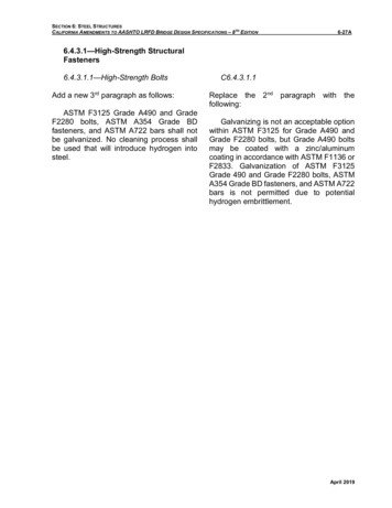
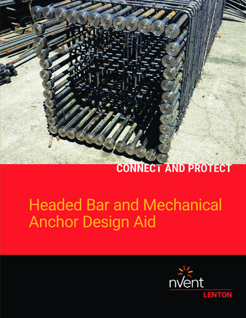
Example B1, Group of anchors with #11 Grade 80 rebarAn engineer’s design includes four nVent LENTON Terminator EL36D6 rebar anchors tobe used with #11 ASTM A706 Grade 80 rebar to anchor a cast in place column to a matfoundation. The Terminators are configured as shown in the image below. Theseanchors meet the definition of an anchor group (defined as "a number of similaranchors having approximately equal effective embedment depths with spacing betweenadjacent anchors such that the projected areas overlap," reference Section 2.3 of ACI318-14 (Section D.1 of ACI 318-11)). Evaluating the anchor group to Chapter 17 of ACI318-14 (Appendix D of ACI 318-11) enables the calculation of concrete breakoutstrength in tension for a single anchor (Ncb) or a group of anchors (Ncbg), pulloutstrength in tension (Npn), and concrete side-face blowout strength in tension for a singleanchor (Nsb) or a group of anchors (Nsbg) to ensure that the calculated performancemeets the design's factored tensile force of 249,600 lbf for the group of anchors (Nua,g),and 62,400 lbf for a single anchor (Nua).nVent.com/LENTON 18
Concrete Breakout Strength in Tension of a Single Anchor (Ncb): Breakout strength intension can be calculated for a single anchor with the equation found in Section17.4.2.1a of ACI 318-14 (D.5.2.1a of ACI 318-11).𝑁𝑁𝑐𝑐𝑐𝑐 𝐴𝐴𝑁𝑁𝑁𝑁ψψ ψ𝑁𝑁𝐴𝐴𝑁𝑁𝑁𝑁𝑁𝑁 𝑒𝑒𝑒𝑒,𝑁𝑁 𝑐𝑐,𝑁𝑁 𝑐𝑐𝑐𝑐,𝑁𝑁 𝑏𝑏As the effective embedment depth (hef) of the anchor is greater than or equal to 11 inand less than or equal to 25 in, Nb is calculated from equation 17.4.2.2b of ACI 318-14(D-7 of ACI 318-11).𝑁𝑁𝑏𝑏 16λ𝑎𝑎 𝑓𝑓′𝑐𝑐 ℎ𝑒𝑒𝑒𝑒5/3SymbolValueUnitACI 318-14ACI 318-11λa1.0-17.2.6D.3.6Modification factor for lightweight concrete,normalweight 1.0.f ’c4,000psi--Specified compressive strength of concrete.hef20.0in--Effective embedment depth of anchor.Description𝑁𝑁𝑏𝑏 16(1.0) 4,000 psi (20 in)5/3𝑁𝑁𝑏𝑏 149,119 lbfnVent.com/LENTON 19
With each of the variables and reduction factors known in equation 17.4.2.1a of ACI318-14 (D-3 of ACI 318-11), Ncb can be solved for.𝑁𝑁𝑐𝑐𝑐𝑐 SymbolValueUnitACI 318-14𝐴𝐴𝑁𝑁𝑁𝑁ψψ ψ𝑁𝑁𝐴𝐴𝑁𝑁𝑁𝑁𝑁𝑁 𝑒𝑒𝑒𝑒,𝑁𝑁 𝑐𝑐,𝑁𝑁 𝑐𝑐𝑐𝑐,𝑁𝑁 𝑏𝑏ACI 318-11DescriptionR17.4.2.1RD.5.2.1Actual projected failure area (ANc) divided bytheoretical projected failure area (ANco), setequal to 1.0 for a single anchor away fromedges.17.4.2.5D.5.2.5Modification factor for edge proximity, whennot affected by edge, set equal to odification factor based on presence orabsence of cracks, 1.25 for no cracks.ψcp,N1.0-17.4.2.7D.5.2.7Modification factor for post-installed anchors,set equal to 1.0 for cast-in anchors.149,119lbf17.4.2.2D.5.2.2Basic concrete breakout strength in tension ofsingle anchor.Nb--𝑁𝑁𝑐𝑐𝑐𝑐 (1.0)(1.0)(1.25)(1.0)(149,119 lbf)𝑁𝑁𝑐𝑐𝑐𝑐 186,399 lbfnVent.com/LENTON 20
According to Section 17.3.1.1 of ACI 318-14 (D.4.1.1 of ACI 318-11), the concretebreakout strength of a single anchor (Ncbg) multiplied by the strength reduction factor(φ) must be greater than or equal to the factored tensile force applied to the anchor(Nua).SymbolφValueUnitACI 318-14𝜑𝜑𝑁𝑁𝑐𝑐𝑐𝑐 𝑁𝑁𝑢𝑢𝑢𝑢ACI 318-110.70-17.3.3(c)D.4.3(c)Ncb186,399lbf17.3.1.1 &17.4.2.1D.4.1.1 &D.5.2.1Nua62,400lbf--DescriptionStrength reduction factor for anchorsgoverned by concrete breakout, whensupplementary reinforcement is not present(Condition B).Nominal concrete breakout strength in tensionof a group of anchors.Factored tensile force applied to anchor orgroup of anchors.(0.70)(186,399 lbf) 62,400 lbf130,479 lbf 62,400 lbfnVent.com/LENTON 21
Concrete Breakout Strength in Tension of Group of Anchors (Ncbg): Breakout strengthin tension can be calculated for a group of anchors with the equation found in Section17.4.2.1b of ACI 318-14 (D.5.2.1b of ACI 318-11).𝑁𝑁𝑐𝑐𝑐𝑐𝑐𝑐 𝐴𝐴𝑁𝑁𝑁𝑁 ′ψψψ ψ𝑁𝑁𝐴𝐴𝑁𝑁𝑁𝑁𝑁𝑁 𝑒𝑒𝑒𝑒,𝑁𝑁 𝑒𝑒𝑒𝑒,𝑁𝑁 𝑐𝑐,𝑁𝑁 𝑐𝑐𝑐𝑐,𝑁𝑁 𝑏𝑏To start, the variable of ANc' (ANc' is used in this design aid to represent a group ofanchors, where ANc is used to represent a single anchor) must be determined accordingto Section 17.4.2.1 of ACI 318-14 (D.5.2.1 of ACI 318-11). In this scenario, the anchorsare all located at least 1.5hef from any edge, therefore, ANc' can be calculated as shownbelow (values for each variable can be found in the diagram at the beginning of thisexample):𝐴𝐴𝑁𝑁𝑁𝑁 ′ 𝑐𝑐𝑎𝑎1 𝑠𝑠1 1.5ℎ𝑒𝑒𝑒𝑒 2SymbolValueUnitACI 318-14ACI 318-11Descriptionca130inR17.4.2.1RD.5.2.1Minimum edge distance to center of anchor.s123inR17.4.2.1RD.5.2.1Center to center spacing of anchors.20in--hefEffective embedment depth of anchor.𝐴𝐴𝑁𝑁𝑁𝑁 ′ (30 in 23 in 1.54(20))2𝐴𝐴𝑁𝑁𝑁𝑁 ′ 6,889 in2ANco is determined by the equation 17.4.2.1c of ACI 318-14 (D-5 of ACI 318-11).𝐴𝐴𝑁𝑁𝑁𝑁𝑁𝑁 9ℎ𝑒𝑒𝑒𝑒 2𝐴𝐴𝑁𝑁𝑁𝑁𝑁𝑁 9(20 in)2𝐴𝐴𝑁𝑁𝑁𝑁𝑁𝑁 3,600 in2nVent.com/LENTON 22
With each of the variables and reduction factors known in equation 17.4.2.1b of ACI318-14 (D-4 of ACI 318-11), Ncbg can be solved for.𝑁𝑁𝑐𝑐𝑐𝑐𝑐𝑐 SymbolValueUnitACI 𝑁 ′𝑁𝑁ψψψ ψ𝐴𝐴𝑁𝑁𝑁𝑁𝑁𝑁 𝑒𝑒𝑒𝑒,𝑁𝑁 𝑒𝑒𝑒𝑒,𝑁𝑁 𝑐𝑐,𝑁𝑁 𝑐𝑐𝑐𝑐,𝑁𝑁 𝑏𝑏ACI 318-11DescriptionR17.4.2.1& 17.4.2.3RD.5.2.1& D.5.2.3Projected concrete failure area of a group ofanchors.17.4.2.1D.5.2.1Projected concrete failure area of a singleanchor not limited by edge or spacing.Actual projected failure area of the group ofanchors (ANc') divided by theoretical projectedfailure area 7.4.2.4D.5.2.4Modification factor for anchor groups loadedeccentrically in tension, set equal to 1.0 if load iscentered in anchor group.ψed,N1.017.4.2.5D.5.2.5Modification factor for edge proximity, when notaffected by edge, set equal to 1.0.ψc,N1.25-17.4.2.6D.5.2.6Modification factor based on presence orabsence of cracks, 1.25 for no cracks.ψcp,N1.0-17.4.2.7D.5.2.7Modification factor for post-installed anchors,set equal to 1.0 for cast-in anchors.149,119lbf17.4.2.2D.5.2.2Basic concrete breakout strength in tension ofsingle anchor.Nb-𝑁𝑁𝑐𝑐𝑐𝑐𝑐𝑐 (1.914)(1.0)(1.0)(1.25)(1.0)(149,119 lbf)𝑁𝑁𝑐𝑐𝑐𝑐𝑐𝑐 356,767 lbfnVent.com/LENTON 23
According to Section 17.3.1.1 of ACI 318-14 (D.4.1.1 of ACI 318-11), the concretebreakout strength of a group of anchors (Ncbg) multiplied by the strength reductionfactor (φ) must be greater than or equal to the factored tensile force applied to thegroup of anchors (Nua,g).SymbolValueUnitACI 318-14𝜑𝜑𝑁𝑁𝑐𝑐𝑐𝑐𝑐𝑐 𝑁𝑁𝑢𝑢𝑢𝑢,𝑔𝑔ACI 318-11Descriptionφ0.70-17.3.3(c)D.4.3(c)Strength reduction factor for anchors governed byconcrete breakout, when supplementaryreinforcement is not present (Condition ominal concrete breakout strength in tension ofa group of anchors.Nua,g249,600lbf--Factored tensile force applied to anchor or groupof anchors.(0.70)(356,767 lbf) 249,600 lbf249,737 lbf 249,600 lbfIn cases where the nominal breakout strength does not meet the required load, theengineer may consider increasing variables such as: anchor spacing, distance fromanchor to concrete edge, effective embedment depth, bearing area of the anchor(Section 17.4.2.8 of ACI 318-14 or D.5.2.8 of ACI 318-11), and/or concrete compressivestrength. Other considerations may include the addition of supplemental reinforcement(Section 17.3.3 of ACI 318-14 or D.4.3 of ACI 318-11), the inclusion of anchorreinforcement, and/or altering the relationship between the effective embedment depthand d (ACI 318 defines d as the "distance from extreme compression fiber to centroid oflongitudinal tension reinforcement, in."), such that the effective embedment depth isgreater than (1.5)(d) – precluding breakout failure, refer to Section 17.4.2.9 of ACI 31814 or D.5.2.9 of ACI
25.4.4.1 of ACI 318-14 (12.6.1 of ACI 318-11), Chapter 17 of ACI 318-14 (Appendix D of ACI 318-11) may be used to perform the necessary design calculations on the headed reinforcing bar, treating it as an anchor. Evaluating the headed rebar to Chapter 17 of ACI 318-14