Transcription
Zimmer PSIKnee SystemFor Use with theNexGen CompleteKnee SystemSurgical Technique
TOCZimmer PSI Knee Surgical TechniqueZimmer PSI KneeSurgical TechniqueTable of ContentsIntra-Operative Guide1Femur Exposure2Position the Femoral PSI Jig3Pin the Distal Cutting Guide Pin Holes4Drill 4-in-1 Cutting Guide Pin Holes5Resect Distal Femur6Place Anterior Cutting Guide Pins7Place 4-in-1 Femoral Finishing Guide8Position Tibial PSI Jig9Verify Tibial PSI Jig Alignment10Pin Tibia Cut Guide Pin Holes11Remove Tibial PSI Jig12Resect Proximal Tibia13Install PSI Tibia Rotational Guideon NexGen Sizing Plate Handles14Set Tibial Rotation16Verify Overall Alignment17Supported Zimmer NexGen Systems18Cleaning/Sterilization MethodsAnd Equipment Inventory19Cleaning19Sterilization Parameters20PSI Knee Reusable Instruments andAdditional Specific Cleaning Instructions20Zimmer PSI Knee Disposable Kits21Reusable Instruments Ordering25Zimmer Contact InformationTOC. 126
Zimmer PSI Knee Surgical TechniqueIntroductionThe patient specific guide components are intended forsingle-use only.OverviewContraindicationsThe Zimmer Patient Specific Knee System consists of:disposable patient specific tibial and femoral instrumentguides (also called PSI jigs), optional bone models, and anoptional Tibial Rotational Guide (to set the axial rotation ofthe tibial component), per the available kits listed in thesection titled “Zimmer PSI Knee Disposable Kits”. A copy of theapproved pre-operative surgical planning is also provided inthe Zimmer PSI Knee packaging to be referenced by the surgeonintra-operatively. The bone models are a reconstruction of thepatient’s knee joint tibial and femur bones from the medicalimaging data, aiding the surgeon in verifying the Zimmer PSIJigs’ placement intra-operatively, they are required to hold aplace in the sterile field prior and during the surgery.The Zimmer PSI Knee system should not be used in any ofthe following situations: in cases with active infections ofthe knee joint, in cases with Hip-Knee-Ankle (HKA) alignmentdeformities larger than 15 varus or valgus, in cases wherefemoral anterior cut first surgical techniques will be used,in cases where 3 Option Fluted or A/P Wedge Stemmed Tibialplates are used, in cases of knee replacement revision surgery,or in cases which are contraindicated for the implant as givenby Zimmer.The customized PSI instrument guides are to be used with thegiven NexGen implant families as described in the followingsection, “Indication for Use”. The Zimmer PSI Knee instrumentguides are placed on the distal femur and proximal tibia intraoperatively, and have pin holes to allow the surgeon to preciselyinsert reference pins, in accordance with the pre-operativesurgical plan, that set the position of the cut guides.INTROComplicationsPossible complications associated with the use of the systemmay include, but are not limited to: infection, complicationdue to misplacement of the implants that may potentially leadto dislocation, leg misalignment or knee ligament imbalance.The occurrence of one of these complications may affect thepatient’s mobility.The PSI Knee Reusable instruments, provided by Zimmer CAS,are listed in the section titled “Reusable Zimmer PSI KneeInstruments”. All other reusable instruments that are partof the applicable standard instrumentation sets, described inthe “Intra-Operative Guide” section, are listed with a NexGenor Posterior Referencing Instruments (PRI) identifier.The scope of this document is to provide information on thesurgical technique, cleaning/sterilization methods, as well asthe available Zimmer PSI Knee kits. The pre-operative guideand instructions for use of the Zimmer PSI Knee Plannerapplication are provided in the Zimmer PSI Knee PlannerSoftware User Guide 97-5970-035-00.Indication for useThe Zimmer PSI Knee System is indicated as an orthopedicinstrument system to assist in the positioning of kneereplacement components. It involves surgical planningsoftware used pre-operatively to plan the surgical placementof the components on the basis of provided patient radiologicalimages with identifiable placement anatomical landmarks,and surgical instrument components that include patientspecific or customized guides fabricated on the basis of thesurgical plan to precisely reference the placement of theimplant components intra-operatively per the surgical plan.The Zimmer PSI Knee System is to be used with the followingfixed bearing knee replacement systems in accordance withtheir indications and contraindications: NexGen CR, NexGenCR-Flex, NexGen CR-Flex Gender, NexGen LPS, NexGen LPS-Flex,NexGen LPS-Flex Gender, Persona CR and Persona PS.INTRO. 1
INTROZimmer PSI Knee Surgical TechniquePrecautionsThe following are general precautions and warnings related tothe use of Zimmer PSI instrument guides: Caution: Federal (U.S.) law restricts this device to sale byor on the order of a physician Zimmer strongly recommends formal Zimmer PSI KneeSystem training prior to use of the system. Contact yourlocal Zimmer representative or the Zimmer Institute(1-855-ZSurgeon or 1-855-978-7436) for more information. The Zimmer PSI Knee System should not be used to performsurgical procedures other than those specified in thissurgical technique. The Zimmer PSI Knee System should be used in conjunctionwith a femur first technique The Disposable Zimmer PSI Knee Instruments, includinginstrument guides and bone models are patient specificand single use and should be discarded after surgery. The Disposable Zimmer PSI Knee Instruments and ReusableZimmer PSI Knee Instruments are provided non-sterile andmust be cleaned and sterilized before use per instructionsprovided in this surgical technique (in the section“Cleaning/Sterilization Methods and Equipment Inventory”).These instructions are also provided with the components,refer to Zimmer PSI Jigs & Bone Models Package Insert(20-8014-043-00). The Disposable Zimmer PSI Knee Instruments have alimited shelf life of 6 months after the manufacturing date,as indicated on the package label. Given the potential forpatient morphological changes, the surgeon will need toreassess the patient to identify any potential changes priorto surgery. In case of any doubt the Zimmer PSI Knee guidesand bone models must not be used. The Disposable Zimmer PSI Knee Instruments are to be usedwith the given implant system per the related pre-operativeplanning. The implant must be used in accordance with itsrespective package labeling. The user should refer to thesurgical technique published by the implant manufacturer. The Disposable Zimmer PSI Knee Instruments can withstandtwo autoclave sterilizations. Re-sterilization is onlypermissible when they have not been in contact withthe patient or otherwise contaminated.INTRO. 2 The Disposable Zimmer PSI Knee Instruments are designedto fit the patient anatomy as it was at the moment when thepatient radiological images were acquired. If the anatomyor condition of the articular surface has changed since theradiological images were acquired, the patient specificinstrument should not be used. If you experience difficulties with the Zimmer PSI Knee Jigsduring surgery, stop using the Jigs and revert to the standard(non-PSI) surgical technique.Warning: Ensure that the delivered Disposable Zimmer PSIKnee Instruments correspond to the intended patient. A copyof the approved surgical plan is provided in the Zimmer PSIKnee packaging. Only use the Disposable Zimmer PSI KneeInstruments if the PSI Case ID marking are both legible onthe Zimmer PSI Knee instrument guides and bone modelsand match the PSI Case ID specific to the intended patient.If the two PSI Case ID markings do not match, DO NOT USEthe Disposable Zimmer PSI Knee Instruments on the patientand notify your Zimmer representative.
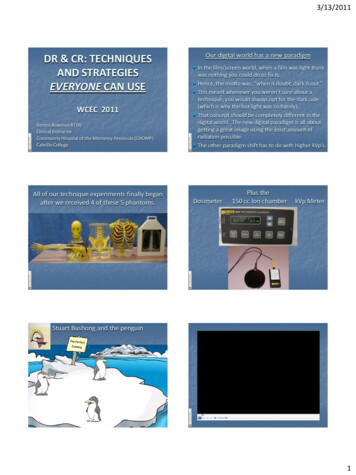
Zimmer PSI Knee Surgical TechniqueINTROThe PSI Case ID can be either 8 or 15 characters, automaticallyassigned based on region. The nomenclature in the followingtable is based off of a fictitious patient with a First Initial: S,the First Two Letters of the Last Name: AM, and Operating Side:Left (L). The Marking on the Guides and Bone Models will bethe whole case ID if it's 8 characters and the first seven digitsif it is 15 characters (Fig. 1).PSI Case ID with 8 CharactersEXAMPLE: SAM1234LPrinted on guides and bone models: SAM1234LSAM1234L----First letterof patientfirst nameFirst 2letters ofpatient lastnameUniquenumberassigned byZimmerOperatedside (Left/Right)----PSI Case ID with 15 CharactersEXAMPLE: SAM123L77DD13USPrinted on guides and bone models: SAM123LSAM123L77DD13USFirst letterof patientfirst nameFirst 2letters ofpatient lastnameUniquenumberassigned byZimmerOperatedside (Left/Right)Year ofpatientbirthdaySurgeoninitialYear whenthe casecreatedRegionwhere thecase IDcreatedFig. 1PSI Case IdentifierWarning: If the Case ID markings do not match the patient,do not use the PSI Knee Instrument Guides and BoneModels on the patient. Notify your Zimmer representativeimmediately.INTRO. 3
SECTION1Intra-Operative GuideIntra-Operative GuideThe Zimmer PSI Knee Instrument Guides, (Jigs), are designedfor use with conventional incision as well as the MIS SubVastus, the MIS Mid-Vastus, and the MIS Medial-Parapatellarapproaches for the placement of given NexGen implant familiesdefined in the “Indication for Use” section. These surgicalapproaches are described in the following Zimmer SurgicalTechniques: Zimmer MIS Multi-Reference 4-in-1 FemoralInstrumentation Surgical Technique (97-5967-002-00) Zimmer NexGen Cr-Flex and LPS-Flex Knees SurgicalTechnique with Posterior Referencing Instrumentation (PRI)(97-5905-002-00)1
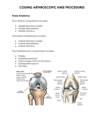
SECTIONFemur Exposure2Femur Exposure Expose the femur and tibia according to the applicablesurgical technique listed under “Intra-Operative Guide”. Look at the mating surfaces of the femoral PSI jig on thefemoral bone model or on the surgical plan (Fig. 2). Remove soft tissues on the bone that could preventgood contact with the PSI jigs, such as the meniscusand fat tissue. Do not remove any osteophytes or cartilage from the femur.Note: If the bone model differs significantly from the actualanatomy in those regions, it is indicated not to use thefemoral PSI jig.Fig. 22
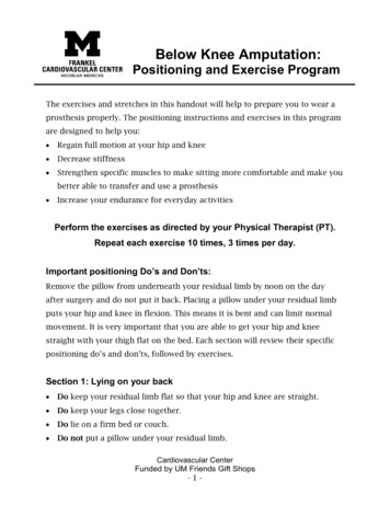
SECTION3Position the Femoral PSI JigPosition the Femoral PSI Jig Position the PSI jig on the distal femur by first locking onthe anterior ridge of the femur and then applying pressuredistally to secure the fit. Avoid rotating the jig towards theposterior condyles, as this would cause excessive flexion(Fig. 3). Use the visual cues on the jig indicating the mechanicalaxis entry point, Whiteside’s Line, and the transepicondylaraxis to help position the PSI jig and decide if properalignment is achieved.Note: If the PSI jig does not have the appropriate snug fit,if there is any doubt on the jig position, or if the markingon the PSI jig does not match the anatomic landmarks,be sure that no soft tissue interferes between the PSI jigand the bone. The positioning of the PSI jig can be doublechecked on the optional bone model. If the above conditionsremain, do not insert pins or drill holes and revert tostandard surgical technique. At this point, intramedullaryinstrumentation should be used.Fig. 33
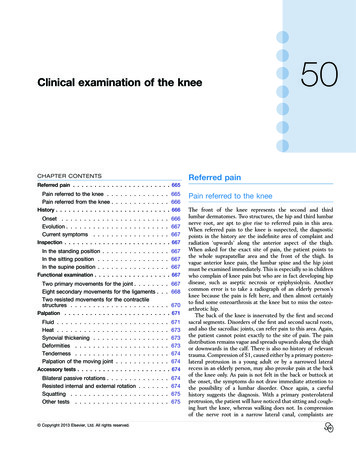
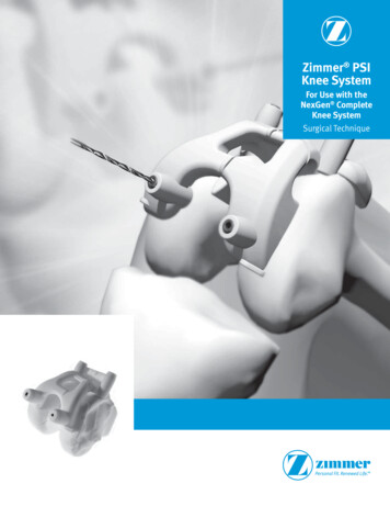
SECTIONPin the Distal Cutting Guide Pin Holes4Pin the Distal Cutting Guide Pin Holes Hold the PSI jig in position by hand, and pin the medialand lateral distal cutting guide pin holes on the PSI jigusing the standard instrument accessory 3.2mm x 75mmPRI Trocar Tipped Drill Pins (2.5 hex) (00-5901-020-00)with the Legacy Instrumentation, or the 3.2 HeadlessTrocar Drill Pin (20-8000-00-16) with the PRI system (Fig. 4).Both pins can be inserted using the Pin/Screw Inserter(00-5901-021-00). Assure accurate placement of the twopins before proceeding.Fig. 4Instruments- OR -3.2 x 75mmTrocar TippedDrill Pin (2.5 hex)00-5901-020-003.2 x 75mmHeadless TrocarDrill Pin20-8000-000-16Pin/ScrewInserter00-5901-021-004
SECTION5Drill 4-in-1 Cutting Guide Pin HolesDrill 4-in-1 Cutting Guide Pin Holes Using the 3.2mm drill bit, available through ZimmerStandard Instrumentation, drill the medial and lateral4-in-1 pin holes of the PSI jig deep enough to ensure thatafter the distal cut, the holes are still visible (Fig. 5).Note: If the drill contacts a trocar pin, DO NOT drill furtherand remove the pin.Fig. 5Instruments3.2mm Drill00-5120-085-005
SECTIONResect Distal Femur6Resect Distal Femur Remove the Femoral PSI jig by sliding it off the pins, leavingthe distal cutting guide pins in place (Fig. 6). In case the Femoral PSI jig gets locked over the bone duringits retrieval, it is recommended to disengage one pin ata time to ease the removal of the PSI jig. If the pins areremoved in the process, re-insert them in the pin holesafter having removed the jig.Fig. 6 Secure the NexGen MIS Distal Cut Guide (00-5967-036-00)or the NexGen PRI 0 Captured/Uncaptured Cutting Head(00-5901-064-00), in the holes marked ‘0’ (Fig. 7).Fig. 7 Check alignment, if desired, and make the cut (Fig. 8).Fig. 8InstrumentsPRI 0 Captured/UncapturedCutting Head00-5901-064-006
SECTION7Place Anterior Cutting Guide PinsPlace Anterior Cutting Guide Pins Remove the medial and lateral distal 3.2mm x 75mmTrocar Tipped Drill Pins with the PRI Multi Pin Puller(00-5901-022-00). For MIS instrumentation: insert two headless pins inthe medial and lateral drilled pin holes and move on tothe next step (Fig. 9). For PRI instrumentation: move on to the next step.Fig. 9InstrumentsMulti Pin Puller00-5901-022-007
SECTIONPlace 4-in-1 Femoral Finishing Guide8Place 4-in-1 Femoral Finishing GuideFor MIS instrumentation Select the applicably sized MIS 4-in-1 Femoral FinishingGuide (silver) or the Flex Femoral Finishing Guide (gold),which coordinates to the surgical plan, both are availablefrom the implant system instrumentation. Place it over thetwo distal pins, (pins for 4-in-1 guide) (Fig 10).Fig. 10 Per the standard technique, adjust the M/L positioning forappropriate placement. Secure the Finishing Guide andremove the pins. Verify resections using the ResectionGuide (00-5977-084-00), commonly known as the 'angelwing', and make the cuts (Fig. 11). Refer to the Zimmer MISMulti-Reference 4-in-1 Femoral Instrumentation SurgicalTechnique for complete instructions (97-5967-002-00).Fig. 111For the PRI instrumentation Attach the PRI Quick Connect Handle (00-5901-034-00)to the appropriate PRI 4-in-1 Flex Femoral Cut Guide(00-5901-043/048-00), in the size per the pre-operationplanning. Both are available through standard implantsystem instrumentation. Place the PRI 4-in-1 cut guide on the femur by aligning the2 pins on the back of the guide with the previously drilledpositioning holes (Fig. 12). Impact the handle until the guide is flush with the femur.For more stability, secure the 4-in-1 guide with additional3.2mm pins. Refer to the Standard Surgical Technique for PRI for morecomplete instructions and the next steps (97-5905-008-010).Fig. 12InstrumentsQuick ConnectHandle00-5901-034-00MIS 4-in-1 FemoralMIS 4-in-1 FlexFinishing GuideFemoral RI 4-in-1 FlexFemoral CutGuide00-5901043/048-008
SECTION9Position Tibial PSI JigPosition Tibial PSI Jig Look at the mating surfaces of the Tibial PSI jig on the tibiabone model or on the pre-operative planning (Fig. 13). Remove soft tissues on the bone that could prevent goodcontact with the PSI jig, such as the meniscus and fatty tissue. Do not remove osteophytes or cartilage from the tibia.Fig. 13 To position the Tibial PSI jig, first ensure good medialcontact between the jig and the bone, confirming that themedial side of the jig is properly wrapped around the bone.Then, press the two arms perpendicular on the plateau andthen jig as a whole to maintain proper placement and fullcontact with the bone. Avoid rotating the jig by pressing toostrongly anteriorly (Fig. 14).Note: If the representation of the bone on the planning recordor the optional Bone Models significantly differs from theactual anatomy in those regions, it is indicated not to use theTibial PSI jig.Note: If the PSI jig does not mate appropriately, or if there isany doubt on the baseplate position or the marking on thePSI jig of the medial third of the tubercle does not match theanatomic landmarks, make sure that no soft tissue interferesbetween the PSI jig and the bone. The position of the PSI Jigcan also be double checked on the optional Bone Model. If theabove conditions persist, DO NOT insert pins or drill holes andrevert to standard surgical technique. Remove the PSI jig fromthe assembly and set the baseplate orientation and rotationon the tibial cut as per standard surgical technique.9Fig. 14
SECTIONVerify Tibial PSI Jig Alignment10Verify Tibial PSI Jig Alignment Insert the PRI Tibia Drop Rod Adaptor (20-8014-014-00) onthe PSI Jig to help position it correctly. Make sure the droprod is flush with the PSI jig and is inserted on the properside by using the left or right laser marking (Fig. 15).Fig. 15PCL Insertion The Drop Rod Adaptor slot lines up with two landmarks, thePCL insertion point and the medial 1/3 of the tibial tubercle(Fig 16).1/3 TubercleFig. 16 Insert Alignment Rod (00-5785-080-00) through PRIDrop Rod Adaptor to verify alignment of the PSI Guide(Fig. 17). Alignment rod should point towards the centerof the malleoli.Fig. 17InstrumentsPSI PRI Tibia DropRod Adaptor20-8014-014-00Alignment Rod00-5785-080-0010
SECTION11Pin Tibia Cut Guide Pin HolesPin Tibia Cut Guide Pin Holes Hold the PSI jig in position and pin the medial and lateraltibia cut guide pin holes of the PSI jig using standardinstrument accessory 3.2mm x 75mm PRI Trocar Tipped DrillPins (2.5 hex) (00-5901-020-00) together with the NexGenPRI Pin/Screw Inserter (00-5901-021-00) (Fig. 18).Note: Avoid applying excessive force on the anterior part of thePSI Tibia jig to prevent adding anterior slope.Note: The PSI drop rod adaptor is designed to stay in placewhile pinning the PSI Tibia jig.Instruments3.2 x 75mmTrocar TippedDrill Pin (2.5 0Fig. 18
SECTIONRemove Tibial PSI Jig12Remove Tibial PSI Jig Remove the PSI Tibial jig gently by hand to avoid pulling thepins out. Verify that both pins are still placed in the drilledholes (Fig. 19). In case the PSI Tibial jig gets locked over the bone duringits retrieval, it is recommended to disengage the medialpin first, either by hand if able or with a pin puller. If thejig is still locked, remove the lateral pin. If pins have beenremoved, re-insert them in the holes after having removedthe jig.Note: Avoid pulling too hard on the jig, as this can damage thedrilled pin hole, possibly causing misalignment.Fig. 1912
SECTION13Resect Proximal TibiaResect Proximal Tibia Align the proper sized Tibial Cut Guide in place on the bonein the holes marked ‘0’, while the pins are still in place(Fig. 20).Fig. 20 Insert a 3.2 mm Trocar Tipped Drill Pin in the oblique holedto further secure the Captured Cut Guide. (Fig. 21).Fig. 21 Verify the alignment of the Captured Cut Guide by insertingthe PRI Alignment Adapter (00-5901-086-00) (Fig. 22).Fig. 22 Use a 1.27 mm (.050-inch) oscillating saw blade throughthe slot on the Captured Cut Guide to resect proximalsurface of the tibia (Fig. 23).Note: The PRI Tibial Cut Guides (00-5901-075-00 and00-5901-076-00) are used in both NexGen Legacy Standardand PRI instrumentation, is available as part as the implantsystem instrumentation.Fig. l Cut Guide,0 , Left00-5901-075-00Tibial Cut Guide,0 , Right00-5901-076-00
SECTIONOptional: Install PSI Tibia Rotational Guide on NexGen Sizing Plate Handles14Optional: Install PSI Tibia RotationalGuide on NexGen Sizing Plate Handles When using the NexGen Offset Sizing Plate Handle(00-5953-096-00), attach the proper NexGen Tibial SizingPlate, as per the pre-operative planning, then insert the PSITibia Rotational Guide on the Sizing Plate Handle by slidingthe open side of the PSI on the handle (Fig. 24).Fig. 24 Push the PSI Rotational Guide until it clips on the tibialbaseplate (Fig. 25).Fig. 25 When using the NexGen Locking Tibial Tray ProvisionalHandle (00-5977-096-00), insert the PSI Tibia RotationalGuide on the Sizing Plate Handle by sliding the handle onthe open side of the PSI Tibia Rotational Guide. The medialthird of the tibial tubercle marking can be used to confirmthe correct orientation (Fig. 26).Fig. 26InstrumentsNexGen LockingTibial TrayProvisional Handle00-5977-096-00NexGen OffsetSizing Plate Handle00-5953-096-0014
SECTION14Optional: Install PSI Tibia Rotational Guide on NexGen Sizing Plate Handles Attach the proper NexGen Tibial Sizing Plate, as defined inthe preoperative planning. Then, push the PSI RotationalGuide until it clips on the tibial baseplate (Fig. 27).Fig. 27Implant/Sizing Plate Handle compatibility Figure 28 shows compatibility between the different tibialimplant brand and the two types of handlesImplant BrandHandle7 Option FlutedStraightCR Porous PeggedStraightCR Precoat PeggedStraightMIS Modular Precoat StemmedOffsetMIS Precoat StemmedOffsetCR All PolyOffsetLPS All PolyOffsetPorous StemmedOffsetPrecoat StemmedOffsetOption StemmedOffsetTM CR MonoblockStraightTM LPS MonoblockStraightTM ModularOffsetFig. 28InstrumentsNexGen LockingTibial TrayProvisional Handle00-5977-096-0015NexGen OffsetSizing Plate Handle00-5953-096-00
SECTIONSet Tibial Rotation15Set Tibial RotationPCL Insertion Slide the PSI Tibial Rotational Guide with the Sizing PlateHandle, as described in the previous step, on the tibial cutguide pins. Mate the PSI Rotational Guide on the anterior surface of thetibia to assess the planned rotation and bone cut coverage. Use the NexGen 25mm Short-Head Holding Pin(00-5977-056-03) to secure the NexGen tibial baseplatewith the PRI Multi Pin Puller (00-5901-022-00) (Fig. 29).Note: If the PSI jig does not mate appropriately, or if there isany doubt on the baseplate position or the marking on thePSI jig of the medial third of the tubercle does not match theanatomic landmarks, make sure that no soft tissue interferesbetween the PSI jig and the bone. If the above conditionspersist, DO NOT insert pins or drill holes and revert to standardsurgical technique. Remove the PSI jig from the assembly andset the baseplate orientation and rotation on the tibial cut asper standard surgical technique.1/3 TubercleFig. 29Instruments25mm ShortheadHolding Pin 00-5977-056-03Multi Pin Puller00-5901-022-0016
SECTION16Verify Overall AlignmentVerify Overall Alignment Insert the drop rod, available through Zimmer standardinstrumentation, in either the NexGen Offset Sizing Platehandle (00-5953- 096-00) or the NexGen Locking Tibial TrayProvisional Handle (00-5977-096-00) to verify the overallalignment of the leg (Fig. 30). When the alignment has been verified, remove the PSIRotational Guide by pushing on its clipping mechanism andpulling back the PSI Rotational Guide. Remove the handleas per the standard surgical technique.Fig. 30InstrumentsNexGen LockingTibial TrayProvisional Handle00-5977-096-0017NexGen OffsetSizing Plate Handle00-5953-096-00PSI PRI TibiaRod Adaptor20-8014-014-00
SECTIONSupported Zimmer NexGen Systems17Supported Zimmer NexGen SystemsFemurCR OptionC, D, E, F, GCR PorousA, B, C, D, E, F, G, HCR PrecoatA, B, C, D, E, F, G, HCR-Flex OptionB, C, D, E, F, G, C-, D-, E-, F-, G-CR-Flex PorousB, C, D, E, F, G, C-, D-, E-, F-, G-CR-Flex PrecoatB, C, D, E, F, G, C-, D-, E-, F-, G-CR-Flex Gender PorousTibiaFluted 7 Option Stem1, 2, 3, 4, 5, 6, 7, 8, 9, 10CR Porous Pegged1, 2, 3, 4, 5, 6, 7, 8, 9, 10CR Precoat Pegged1, 2, 3, 4, 5, 6, 7, 8, 9, 10MIS Modular PrecoatStemmed2, 3, 4, 5, 6, 7, 8C, D, E, F, G, C-, D-, E-, F-, G-MIS Precoat Stemmed1, 2, 3, 4, 5, 6, 7, 8, 9, 10CR-Flex Gender PrecoatC, D, E, F, G, C-, D-, E-, F-, G-Option Stemmed3, 4, 5, 6, 7, 8LPS OptionA, B, C, D, E, F, G, HPorous Stemmed1, 2, 3, 4, 5, 6, 7, 8, 9, 10LPS PrecoatB, C, D, E, F, GLPS PorousB, C, D, E, F, GPrecoat Stemmed1, 2, 3, 4, 5, 6, 7, 8, 9, 10LPS-Flex OptionC, D, E, F, GCR TM Monoblock3, 4, 5, 6, 7, 8LPS-Flex PorousA, B, C, D, E, F, GLPS TM Monoblock3, 4, 5, 6, 7, 8LPS-Flex PrecoatA, B, C, D, E, F, GTM Modular2, 3, 4, 5, 6, 7, 8LPS-Flex TivaniumC, D, E, F, GLPS-Flex GenderC, D, E, F, GCR All - Poly3, 4, 5, 6, 7, 8LPS-Flex Gender PorousC, D, E, F, GLPS All -Poly3, 4, 5, 6, 7, 818
SECTION18Cleaning/Sterilization Methods And Equipment InventoryCleaning/Sterilization Methods AndEquipment Inventory Disposable Zimmer PSI Knee Instruments are providednon-sterile and are single use. They must be cleaned andsterilized by the end user before the surgery. The ReusableZimmer PSI Knee Instruments must be cleaned after useand prior to sterilization. The instruments should not be sterilized in the protectivebag or packaging supplied with them. All sterilizationsshould be performed using standard and regularlymaintained equipment. In the case a surgery is re-scheduled or in the case ofanother issue requiring the Disposable Zimmer PSIKnee Instruments to be re-cleaned and re-sterilized,the Disposable Zimmer PSI Knee Instruments can onlybe re-cleaned and re-sterilized once for a given patient,if they have not been otherwise contaminated. This isto avoid patient infection and contamination. Validatedcleaning methods have not been established for suchre-use conditions. Cleaning and Sterilization methods aredescribed below.Warning: Before every surgery, the user must verify that alljigs (including bone models) and instruments have beencleaned and sterilized.CleaningFor cleaning, both the single use Zimmer PSI Knee Jigs(including bone models) and the reusable instrumentsrequire manual cleaning steps as follows (additionalcomponent-specific cleaning instructions are provided inthe next subsections):1. Pre-soak components in an enzyme solution.2. Scrub components with a soft bristle brush to remove allvisible soil.3. Use a water jet to flush difficult access areas andclosely mated surfaces (see areas labeled “A” in theimages in the following tables: “Reusable Zimmer PSIKnee Instruments” and “Disposable Zimmer PSI KneeInstruments”).4. Ultrasound clean (Sonification) all components in anenzyme solution with a minimum cycle time of 5 minutes.5. Thoroughly rinse and dry all components.19
SECTIONCleaning/Sterilization Methods And Equipment Inventory18Sterilization Parameters All components (disposable and reusable) require steamsterilization before use per the following methods (Fig. 31).Steam Sterilization (Autoclave)Cycle TypeTemperature1Exposure Time1Minimum Dry Time2Minimum Cool Time3Pre-Vacuum132 C (270 F)4 minutes30 minutes30 minutes1Both the given cycle temperature and time can be increased to 134 C 3 C (273.2 F 5.4 F) and 18 minutes according to local requirements outside of theUnited States such as in the European Union.2Drying times vary according to load size and should be increased for larger loads3Cooling times vary according to the type of sterilizer used, device design, temperature and humidity of ambient environment, and type of packaging used.Cooling process should comply with ANSI/AAMI ST79.Fig. 31Reusable Zimmer PSI Knee Instruments andAdditional Specific Cleaning Instructions The table below shows the reusable instruments forNexGen Zimmer PSI Jigs Kit. Additional specific cleaninginstructions as applicable to each instrument are provided(Fig. 32):Catalog No.InstrumentQtySterilization and specificcleaning instructionsAdditional Notes20-8014-014-00PRI Drop Rod Adaptor1AutoclaveRe-usable,Additional specific cleaningrequirements : Use a water jetto flush difficult access areas(see areas labeled “A”)Provided non-sterileAAFig. 32Note: The Zimmer PSI NexGen Legacy Jigs Kit mustbe used together with the Tibia PRI Cut guide(left/right) (00-5901-075/076-00).20
SECTION19Zimmer PSI Knee Disposable KitsZimmer PSI Knee Disposable Kits The table below shows the available Disposable Zimmer PSIKnee Instruments. Additional specific cleaning instructions,as applicable, for each component are provided (Fig. 33):InstrumentQtySterilization and specificcleaning instructionsAdditional NotesZimmer PSI Knee NexGen Legacy Jigs1AutoclaveSingle use,Provided non-sterileCatalog No.20-8070-003-01LeftAdditional specific cleaningrequirements : Use a water jetto flush difficult access areas(see areas labeled immer PSI Knee NexGen LegacyJigs & Tibia RotationAA20-8070-004-02RightAAAFig. 3321AutoclaveAdditional specific cleaningrequirements : Use a water jetto flush difficult access areas(see areas labeled “A”)Single use,Provided non-sterile2
SECTIONZimmer PSI Knee Disposable KitsInstrumentQtySterilization and specificcleaning instructionsAdditional NotesZimmer PSI Knee NexGen LegacyJigs & Offset Tibia Rotation1AutoclaveSingle use,Provided non-sterileCatalog No.20-8070-005-01LeftAdditional specific cleaningrequirements : Use a water jetto flush difficult access areas(see areas labeled immer PSI Knee NexGen PRI JigsLeftA1AutoclaveAdditional specific cleaningrequirements : Use a water jetto flush difficult access areas(see areas labeled “A”)Single use,Provided non-sterile2A20-8070-006-02RightAFig. 33 (continued)22
SECTION19Zimmer PSI Knee Disposable KitsInstrumentQtySterilization and specificcleaning instructionsAdditional NotesZimmer PSI Knee NexGenPRI Jigs & Tibia Rotation1AutoclaveSingle use,Provided non-sterileCatalog No.20-8070-007-01LeftAdditional specific cleaningrequirements : Use a water jetto flush difficult access areas(see areas labeled tZimmer PSI NexGen PRI Jigs Kit(including Offset Tibia Rotational Guide)AA20-8070-008-02RightAAFig. 33 (continued)23A1AutoclaveAdditional specific cleaningrequirements : Use a water jett
Software User Guide 97-5970-035-00. Indication for use The Zimmer PSI Knee System is indicated as an orthopedic instrument system to assist in the positioning of knee replacement components. It involves surgical planning software used pre-operatively to plan the surgical placement of the components on the basis of provided patient radiological