Transcription
ADTECHNICAL REPORT ARCCB-TR-98007RESIDUAL STRESS IN A SWAGEAUTOFRETTAGED STEEL CYLINDERWITH SEMI-CIRCULAR MID-WALL CHANNELSS. L. LEEE. HYLANDJ. NEESED. WINDOVERMAY 1998US ARMY ARMAMENT RESEARCH,DEVELOPMENT AND ENGINEERING CENTERCLOSE COMBAT ARMAMENTS CENTERBENET LABORATORIESWATERVLIET, N.Y. 12189-4050APPROVED FOR PUBLIC RELEASE; DISTRIBUTION UNLIMITED19980617 046 fie QtfALTT7 INSPECTED 1
DISCLAIM«The findings in this report are net to be construed as in officialDepartment of tho Amy position unless so designated by othor authoriseddocuments,Tho uso of trade name (a) and/or manufacturer(s) doos not constitutean official indorsement OT approval.DESTRUCTION NOTICEFor clajsifitd documents, follow tho procedures in DoO S200.22-M,Industrial Security Manual, Stetion IX-19 or DoO S200.1-R, InformationStcurity Progr** Regulation, Chapter IX.For unclassified, liaitad documents, destroy by v\y aothod that willprevent disclosure of contents or reconstruction of ths docuaent.For unclassified, unlimited documents, destroy when the report isno longer needed.Do not return it to the originator.
Form ApprovedREPORT DOCUMENTATION PAGEOMB No. 0704-0188Public reporting burden for this collection of information is estimated to average 1 hour per response, including the time for reviewing instrunions searching existing data sourcesgather Ä maintaining the data needed, and completing and reviewing the collection of information. Send »""«« rega'drng th« bui den es mate or any othe apec M thisro! ertion of information mcludinq suggestions for reducing this burden, to Washington Headquarters Services. Directorate for information Operations and Reports l ib jettersonDa!/*Sgh*ai.iZe uoi! Arlington VA 22202-4302. and to the Office of Management and Budget. Paperwork Reduction Project (0704-018S). Washington, DC 20503.1. AGENCY USE ONLY (leave blank)2. REPORT DATEMay 19983. REPORT TYPE AND DATES COVEREDFinal5. FUNDING NUMBERS4. TITLE AND SUBTITLEAMCMS No. 6111.01.91 Al.1RESIDUAL STRESS IN A SWAGE AUTOFRETTAGED STEELCYLINDER WITH SEMI-CIRCULAR MID-WALL CHANNELS6. AUTHOR(S)S.L. Lee, E. Hyland, J. Neese, and D. Windover8. PERFORMING ORGANIZATIONREPORT NUMBER7. PERFORMING ORGANIZATION NAME(S) AND ADDRESS(ES)U.S. Army ARDECBenet Laboratories, AMSTA-AR-CCB-0Watervliet, NY 12189-4050ARCCB-TR-9800710. SPONSORING/MONITORINGAGENCY REPORT NUMBERS. SPONSORING/MONITORING AGENCY NAME(S) AND ADDRESS(ES)U.S. Army ARDECClose Combat Armaments CenterPicatinny Arsenal, NJ 07806-500011. SUPPLEMENTARY NOTESPresented at the SEM Spring Conference on Experimental and Applied Mechanics, Bellevue, WA, 2-4 June 1997.Published in proceedings of the conference.12b. DISTRIBUTION CODf12a. DISTRIBUTION/AVAILABILITY STATEMENTApproved for public release; distribution unlimited.13. ABSTRACT (Maximum 200 words)X-ray diffraction residual stress distribution analysis was performed for a swage autofrettaged, thick-walled, A723 steel compound cylinderwith axial semi-circular mid-wall channels. Because of the existence of high stress gradient components in the stress distribution, the effectof spatial resolution and the x-ray beam spread function were investigated. Experimental stress measurements were compared with results fromTresca's model of a partially autofrettaged solid cylinder. Measured residual stresses were interpreted using an ABAQUS finite element model.Our experimental results verified most features of the predicted hoop stress distribution, including the high stress gradients and compressivestresses near the channel root areas. However, significantly reduced compressive stress levels were observed both near the bore and near thechannel roots. An overestimate of fatigue lifetime could result if the reduction of compressive stresses observed experimentally were not takeninto account. In solid autofrettaged cylinders, reduction of compressive stresses near the bore has been attributed to the Bauschinger effect.However, there is no analytical model incorporating the Bauschinger effect in the current geometry. This work demonstrated that theintroduction of the semi-circular channels in a solid cylinder significantly modified the magnitude and location of stress fields. Both the boreand the channel roots are critical sites for stress concentration. Our analysis further determined that the channel roots were the most criticalsites where cracks and failure should occur. Fatigue test results verified that cracking and failure occurred at the channel roots.14. SUBJECT TERMS15. NUMBER OF PAGESSwage Autofrettage, Perforated Cylinders, Bauschinger Effect,Residual Stress, Finite Element Analysis16. PRICE CODE17. SECURITY CLASSIFICATIONOF REPORTUNCLASSIFIEDNSN 7540-01-280-550018. SECURITY CLASSIFICATIONOF THIS PAGEUNCLASSIFIED1419. SECURITY CLASSIFICATIONOF ABSTRACTUNCLASSIFIED20. LIMITATION OF ABSTRACTULStandard Form 298 (Rev. 2-89)Prescribed by ANSI Std Z39-18298-102
TABLE OF CONTENTSPageINTRODUCTION1EXPERIMENTAL METHODS2RESIDUAL STRESS DISTRIBUTION USING TRESCAS YIELD CRITERION3FINITE ELEMENT MODELING4SIMULATION OF RESOLUTION EFFECT5X-RAY BEAM SPREAD FUNCTION7X-RAY RESIDUAL STRESS FROM ID TO OD7EXPERIMENTAL DATA COMPARED TO TRESCAS MODEL9RESIDUAL STRESS BORE TO CHANNEL ROOT USING A PARTIAL BEAMTECHNIQUE9FATIGUE TEST RESULTS11RESIDUAL STRESS EFFECTS11CONCLUSIONS12REFERENCES13LIST OF ILLUSTRATIONS1.2.3.4.Upper left portion of a cylinder cross section with axial semi-circularchannels, showing channel root, ID, OD, and stress measurement paths1Residual stress distribution using Tresca's yield criterion at 50, 60, 70percent overstrain of a solid cylinder under internal pressure4Parker's finite element modeling predictions of hoop residual stressdistribution and hoop stress plus bore pressure at 434 MPa from cylinderbore to channel roots at 20,40, 60, 80 percent overstrain5Simulation of resolution effect in x-ray stress analysis for a residualstress distribution containing high stress gradients6i
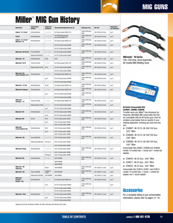
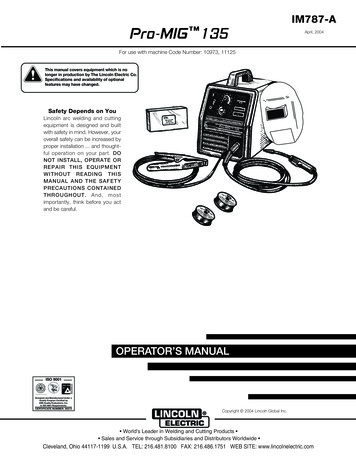
INTRODUTIONSwage autofrettage is an important manufacturing process for high temperature, highpressure vessels. It entails the operation of driving an oversized mandrel through the interiorbore of a cylinder to cause a redistribution of residual stresses within the cylinder. When acylinder is swage autofrettaged, compressive residual stresses are generated near the cylinderbore to counter the high tensile stresses during operation. The residual stress distribution inswage autofrettaged, thick-walled, solid cylinders has been investigated extensively (refs 1-3),resulting in significantly improved fatigue life.To design a cylinder with axial perforations for high temperature pressure vesselapplications, a compound cylinder was constructed. The compound cylinder consisted of a linerand a jacket, both made from A723 steel. The liner, with semi-circular channels cut at the outersurface, was shrunk fit into the jacket. The unit was then subjected to swage autofrettage toinduce favorable residual stresses in order to improve its fatigue life.Figure 1 displays the upper left portion of a cylinder cross section, showing the locationof the mid-wall channels. The "channel root," shown in the figure, is defined as the point on thechannel surface that is closest to the bore of the cylinder. The inside diameter (ID), and outsidediameter (OD) of the cylinder are labeled. Line OAD defines a direction from the origin of thecylinder through the channel root, and line OEF defines a direction from the origin passingthrough the mid-point between two channels.Figure 1. Upper left portion of a cylinder cross section with axial semi-circularchannels, showing channel root, ID, OD, and stress measurement paths.
In this work, x-ray residual stress distribution analysis was performed to characterize theeffects of axial mid-wall channels. Because there were high gradient components in the residualstress distribution, we investigated the effect of spatial resolution on stress determination andobtained x-ray beam images to determine the effective beam spread. An optimized partial beamtechnique was used to take experimental measurements in the channel root areas, where highstress gradients were found.The experimental stress distribution was compared with a model based on Tresca's yieldcriterion for a solid cylinder under internal pressure. The results were also compared to a twodimensional, elastic-plastic, finite element deformation model of a perforated cylinder underinternal pressure (ref 4). Experimental results verified most of the features predicted bymodeling, including the channel root areas where high stress gradients and compressive residualstresses were observed. However, the levels of the hoop compressive stress observed, both nearthe cylinder bore and at the channel roots, were significantly reduced from model predictions.The Bauschinger effect reduces yield strength in compression due to a prior tensile plasticoverload. In swage autofrettaged, solid cylinders, reduced hoop compressive stresses near thebore, characterized by a hook-like stress distribution, were observed experimentally (refs 2,3).Milligan et al. (ref 5) studied the Bauschinger factor dependence on tensile plastic overstrain.Lee et al. (refs 2,3) compared experimental residual stresses in a swage autofrettaged cylinderwith predictions from an ABAQUS finite element, swage autofrettage model, which predicted ahook. Chen (ref 6) developed a one-dimensional analytical model of a solid cylinder,incorporating both the Bauschinger effect and strain-hardening for a solid cylinder under internalpressure. Then Chen et al. (ref 7) made a comparison of this model to the experimental stressdistribution. Currently, no analytic model is available to predict the Bauschinger effect in acylinder of the present geometry, or to determine its effect on the residual stress distribution atthe bore and at the channel roots.The current investigation demonstrated that compared to a solid cylinder, the introductionof mid-wall channels significantly modified the magnitude and location for stress concentrationsand altered the potential sites for cracks and failure. Based on our analysis, both the bore and thechannel roots are potentially critical sites, with the channel roots being the most critical. Whenthe cylinder was subjected to fatigue testing to failure, all cracks initiated at the channel roots.These cracks grew in a direction perpendicular to the channel surface from the channel rootstoward the bore until failure occurred (from point B toward A in Figure 1).EXPERIMENTAL METHODSRings were cut from four autofrettaged cylinders for x-ray evaluation. The cylinders hada ratio of OD to ID of approximately 1.8. Two of the cylinders were fatigue tested and ringswere cut from the chamber section. The other two cylinders were not subjected to fatigue testing,and rings were cut closer to the rifling section.
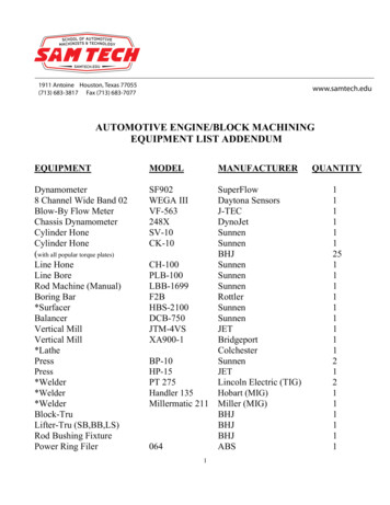
An electropolishing operation was performed using a mixture of sulfuric and phosphoricacids to remove approximately 0.254-mm (10 mils) from the surface of the cross sections. Sincethe most extensive study was performed on a cylinder that was not subjected to fatigue testing,the results from this cylinder will be reported. A TEC portable stress analyzer equipped with aposition-sensitive proportional counter was used to take experimental measurements. ChromiumK-a radiation reflected from the {211} peak of martensitic steel at 156.41 26. This reflectionwas used for x-ray diffraction stress analysis on the cross section of the cylinder. A sample stage,equipped with x and y micrometers, allowed stress measurements at a minimum of 0.025-mmintervals.RESIDUAL STRESS DISTRIBUTION USING TRESCA'S YIELD CRITERIONFor a solid, thick-walled cylinder under internal pressure, residual stress distribution dueto the mechanical overstrain may be evaluated based on Tresca's yield criterion, assuming anopen-ended condition (az 0) (ref 8). The hoop residual stress radial distribution in the plasticregion a r p of a partially overstrained cylinder is given byG,p ay {[a2/(b2 - a2 )](1 b2/r2 )[(p2 - b2 )/2b2 - log (p/a)] [(p2 b2 )/2b2 - log (p/r)]} (1)In the elastic region, p r b, the hoop residual stress distribution is given byste oy (1 b2/r2) {(p2/2b2) [a2/(b2 - a2)] [(p2 - b2 )/2b2 - log (p/a)]}whereOyGtp yield strengthhoop stress in plastic zonedear hoop stress in elastic zonebore radius, b outside radiusvariable radius, p elastic-plastic interface radiusFigure 2 plots the residual stress predictions from Tresca's model for a solid cylinderunder 50, 60, and 70 percent overstrain, assuming a yield strength of 1116 MPa (162 Ksi),showing the elastic and plastic zones.(2)
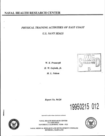
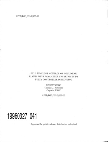
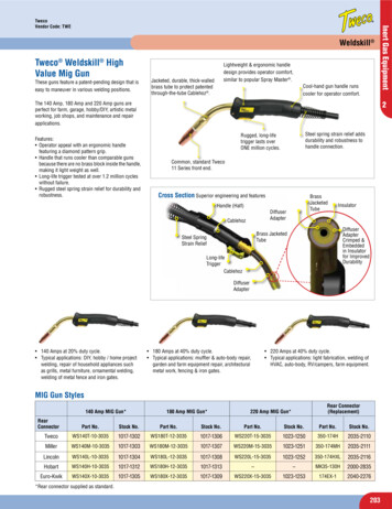
Radial Distance from Bore (mm)10203040506070400A - autofrettage, 35 mmB - autofrettage, 42 mmC - autofrettage, 49 mm-*- 50% Hoop -*- 60% Hoop -*- 70% Hoop- -50% Radial -»-60% Radial -*-70% Radial-800Figure 2. Residual stress distribution using Tresca's yield criterion at 50, 60, 70percent overstrain of a solid cylinder under internal pressure.FINITE ELEMENT MODELINGThe cylinder consisted of 24 evenly spaced axial channels requiring only a l/48th sectionof the cylinder to be modeled by symmetry considerations. A two-dimensional ABAQUSelastic-plastic, quasi-static, finite element model of the perforated cylinder is in progress. Severalloading steps have been taken including the autofrettage process, removal of the autofrettageload, load pressure for firing operation, relaxation of the firing pressure, and final residual stressstate. Results from this ABAQUS modeling and comparison with experimental measurementsare reported in a separate related paper (ref 7).To predict the structure changes due to the introduction of axial channels, Parker et al.(ref 4) performed elastic and elastic-plastic finite element analyses using an alternative mesh,which was biased more toward the channels. This model assumed semi-circular and semielliptical channels for a cylinder of similar geometry but slightly different dimension. Figure 3shows the calculated hoop residual stress radial distribution from the cylinder bore to the channelroot for 20, 40, 60, and 80 percent overstrain.
1500ChannelRootID-COSftoldualSfatn(Soni-cfccle)« lSIra»(SwnMrde)************ **20%RaIdualStnn(Swni-eiicle)«IQIIIIIIH- 80S RMMuaKpmsurt(Swni-clrcl«)-60% ftaidual prawra(S*mi-cirele) ,40% RtsldiHltprtuura(Stmi-drele) 100084.589.594.599.5104.520% Rnidual pntMira(Stmi-eircla)Figure 3. Parker's finite element modeling predictions of hoop residual stressdistribution and hoop stress plus bore pressure at 434 MPa from cylinderbore to channel roots at 20,40,60,80 percent overstrain.High compressive stresses were observed, near the bore, gradually decreasing toward thechannel tip. Near the channel root area, a high positive stress gradient was followed by a highnegative stress gradient. The lower curves in the figure show maximum hoop compressiveresidual stresses of -350 to -700 MPa at the bore, and -600 to -900 MPa at the channel rootsdependent on the percentage overstrain. The upper curves show residual stress plus bore loadingat 434 MPa at various percentages of overstrain. The upper curves also imply that maximumhoop stress occurred at approximately 2-mm from the tip of the channel root, at a magnitude of600 to 1100 MPa. Failure should occur approximately 2-mm beneath the channel roots.SIMULATION OF RESOLUTION EFFECTThe predicted residual stress distribution shown in Figure 3 contains high stress gradientcomponents near the channel root areas. Resolution in the x-ray measurement system cansignificantly affect the accuracy of the measurement of stresses containing high stress gradients.Diffractometer geometry, optical aperture, and range of angles used for the -tilts define theresolution in an Q-diffractometer. X-ray stress analysis is based on a linear variation of thelattice spacing d versus sin2vP utilizing multiple Y-tilts. Due to the finite size of the slits andcollimators, x-ray stress measurement gives the average stress in the irradiated surface areadefined by the x-ray beam.
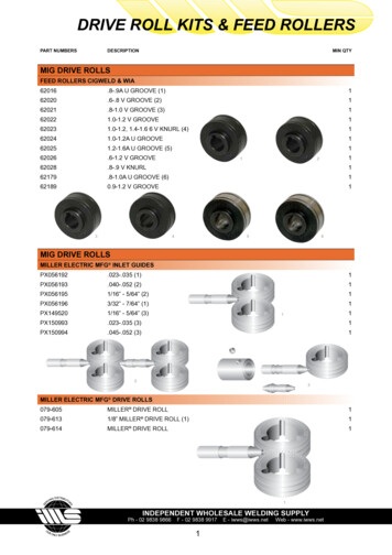
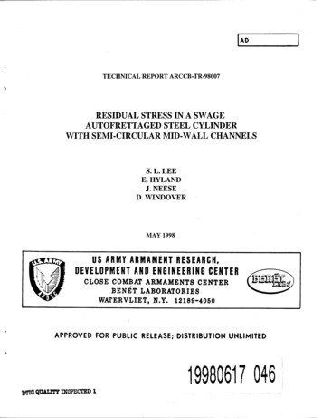
Figure 4 illustrates the effects of three-point averaging and five-point averaging on stressmeasurement using the predicted stress distribution. The model values come from Figure 3 at 60percent overstrain. The three-point averaging corresponds to a lateral resolution of 1.2-mm, andthe five-point averaging corresponds to a lateral resolution of 2.0-mm. The curves show that theaveraging process has a very minor effect on the relatively flat residual stress distribution, but hasa major effect when high stress gradients are present, such as at the channel root areas.Measuring system resolution can affect the magnitude of the stresses, and can shift the maximumstress peaks causing erroneous stress measurements. In this work, optimized collimatordiameters and slit widths were used to perform the measurements.Distance from Bore (mm)80859095100105110105110200Q.5 -20010tos -400re -600a Model Values - 0.4 mm resolution3 point averaging -1.2 mm resolution-800 -1000Distance from Bore (mm)80859095100200IDQ.-200«i: -400(/)751CO -600 UCC-800-Model Values - 0.4 mm resolution5 point averaging - 2.0 mm resolution-1000Figure 4. Simulation of resolution effect in x-ray stress analysis for a residual stressdistribution containing high stress gradients. Top graph illustrates three-pointaveraging of Figure 3 data. Bottom shows five-point averaging.
X-RAY BEAM SPREAD FUNCTIONThe TEC stress analyzer utilizes a divergent beam geometry, with 30-mm longcollimators and slits to define the beam. The x-ray beam can be considered almost parallel. Thebeam-spread function for various diameter collimators and slit widths was investigated byexposing x-ray films under the beam at various F-tilts. Figure 5 shows similar TEC images ofcollimators and slits at *F -45 , 0 , 45 using a cross wire (ref 9). Very slight beam spreadingin the lateral direction was observed. For a 1-mm diameter collimator, lateral resolution stayed at1 to 1.1-mm. In the vertical direction, a slightly larger beam spread can be expected. This spreadis intrinsic to the sin2vF method, and the magnitude of the spread depends on the size of thecollimator, slit, and the *F scan range used. The vertical beam spread would be small comparedto the theoretical stress gradients in the vertical direction near the channel roots. 5 mm45 2 mm4 mm3 mmRound SlitsTip IF\r1 mm 0 -45 Rectangular Slits45 0 »M »I-- —-s -45 Figure 5. Lateral (horizontal) and vertical x-ray beam spread function.X-RAY RESIDUAL STRESS FROM ID TO OD (NO IMMEDIATE CHANNEL ROOTAREAS)A finite element modeling study of the effect due to slicing has been conducted by O'Hara(ref 10). Results showed that the slicing effect decreases with increasing slice thickness. Thiseffect should be small for the slices under investigation due to their thickness. Optimizedcollimators of 0.5-mm and 1-mm diameter were used for data acquisition. A partial beamtechnique described below was necessary to take stress measurements in the channel root areas.
Directions OAD and OEF are defined in Figure 1. Figure 6 depicts the radial distributionof hoop residual stresses, from ID to OD, along these directions. The figure shows thatcompressive residual stresses near the bore at -600 MPa gradually diminished, and turned toslightly tensile at 80 MPa near the channel root. Measured stress abruptly changed tocompressive stress at the channel root with only one data point of -100 MPa. The maximumcompressive stress near the bore was -750 MPa and occurred approximately 3-mm from the bore.The decreased compressive stresses near the bore were similar to stresses observed in solidcylinders. When comparing modeling hoop stresses in Figure 3 to experimental stresses inFigure 6, good agreement was reached. Deviations occurred at the bore and at the channel roots,where reduced compressive stresses were observed. In the outer jacket, residual stress wasmostly tensile, between approximately 100 to 250 MPa.0400-j5Radial Distance from Bore (mm)15 20 25 30 35 40 45 )y. 5-400g -600 MO OEF (Between two channels) OAD (Through a channel)Channel-80029 mmID6.4 mm28.5 mmOD-1000Figure 6. X-ray hoop residual stress distribution along paths OAD and OEF fromcylinder bore to OD (without detailed analysis for the channel root areas).Mid-channel stresses along direction OEF were similar to stresses along OAD, with noteddifferences when approaching the channel root areas. Note also that the mid-channel stresseschanged abruptly at the liner-jacket interface from -300 MPa in the liner to 100 MPa in thejacket. There was a long range of relatively flat compressive stress distribution left of thechannel root, approximately 13 to 25-mm from the bore, which helped to arrest cracks fromfurther growth.
EXPERIMENTAL DATA COMPARED TO TRESCA'S MODELFigure 2 shows the stress distribution predicted from Tresca's yield criterion for a solidcylinder of the same ID and OD dimension under 50, 60 and 70 percent overstrain. Figure 7shows Tresca stresses at 60 percent overstrain compared with experimental stress measurements.The triangles represent raw experimental data, while the solid line is Tresca's curve. Thecomparison shows fairly good agreement except near the bore and the channel roots.040010Radial Distance from Bore (mm)15 20 25 30 35 40 45 50556065TFigure 7. Comparison of experimental residual stress distribution alongOAD from ID to OD with Tresca's solid cylinder 60 percent overstrain.RESIDUAL STRESS BORE TO CHANNEL ROOT USING A PARTIAL BEAMTECHNIQUEFigure 8 shows the residual stress at critical locations A, B, C, and D, representing thebore, the channel root, the channel top, and OD, respectively. The residual stress can bemeasured using an unconventional partial beam technique. However, a full x-ray beam isgenerally recommended to perform x-ray stress analysis. The partial beam technique requiresmonitoring of the reflected beam intensity, overriding the system low-count rate limit; it alsorequires extra shielding for possible stray x-rays due to the vertical surfaces inside the channelwalls. This method is suited for the channel root areas where high stress gradients and highradius of curvature make conventional residual stress measurements difficult. Errors of 100 MPa(15 Ksi) would be expected depending on the percentage of the beam used in the measurement.In normal x-ray analysis, errors of 35 MPa (5 Ksi) would be expected.
Figure 8. Geometry of the experimental set-up for x-ray measurements at cylinder bore A,channel root B, channel top C, and at outside diameter D using a partial beam technique.The open squares in Figure 9 illustrate hoop residual stress from bore to channel rootusing the partial beam technique. The data were taken from a different channel than that used inFigure 6. Compressive stresses of -550 MPa near the bore decreased in magnitude, turningslightly tensile at 100 MPa near the channel root, and then abruptly turning into compressivestresses. The maximum compressive stress measured at the channel root was -200 MPa. Thestress distribution curves from bore to channel root in Figures 6 and 9 were similar. However,Figure 9 shows a less pronounced Bauschinger effect near the bore, with the number ofmeasurement points at the channel root extended. A theoretical ascending slope of 200 MPa/mm(29 Ksi/mm) and a descending slope of -345 MPa/mm (-51 Ksi/mm) were obtained from Figure3. The measured experimental ascending slope was 220 MPa/mm (32 Ksi/mm) and thedescending slope was -282 MPa/mm (-41 Ksi/mm).Radial Distance from the Cylinder Bore (mm)()510152025301500-O/100018 8cnStresses ina.2W ** *" v -'\ftQ.OOX-500 OABAQUS Stresses at 434 Mpa Bore Pressure—D—Measured Residual Stresses— —Residual Stress Bore Pressure-1000 Figure 9. Residual stress from cylinder bore to channel root usingoptimized collimator and slit, and a partial beam technique.10
A comparison of residual stress levels in Figures 3, 6, and 9 showed that observedresidual stresses were much less than predicted at the cylinder bore and at the channel roots. Themeasured reduction in compressive stress at the bore compared to the maximum residual stresswas 200 MPa. The maximum compressive stresses occurred approximately 2 to 3-mm from thebore. This reduced bore stress has been attributed to the Bauschinger effect, not included inParker's model.FATIGUE TEST RESULTSOperational stresses superimpose on the locked-in residual stresses to determine thesafety operation and fatigue life of a component. Current residual stress analysis indicates thatcracks should be expected to initiate at subsurfaces just beneath the channel roots, where residualstress plus bore pressure is the most tensile. However, from experience, cracks always initiate atsurfaces.The cylinder, which was fatigue tested to failure, was cut and examined by magneticparticle inspection and by visual observation. When it was cut into slices, cracks were observed.All of the cracks initiated at or near the center of the channel root areas of the liner. The cracksgrew in a direction perpendicular to the surface of the channel toward the bore, direction BA inFigure 1, until complete failure of the unit.RESIDUAL STRESS EFFECTSFrom a residual stress point of view, the bore and the channel roots are competinglocations of stress concentration. The current investigation determined that compressive stresslevels were much greater at the bore than at the channel roots. The open diamonds in Figure 9are the most recent ABACUS hoop stresses in the perforated cylinder under 434 MPa borepressure (ref 7). The black circles in Figure 9 show combined residual stress with operationalbore pressure. These data show the channel roots are the most critical sites for cracks and failure.Cracks initiated at the channel because residual stress superimposed on the operational stress wastensile. Furthermore, tensile stresses immediately under the channel root surface helped thecracks grow farther, leading to failure of the component.At the channel root, observed stresses of -300 MPa were significantly lower than thepredicted stresses of -800 MPa for 60 percent overstrain. The 500 MPa difference could modifythe upper curves in Figure 3, which represent residual stress plus bore pressure. This changecould make the stress more tensile at the channel roots, and failure would be more likely to occurat the channel roots than at the bore. It could also shift the maximum tensile stress in Figure 3toward the channel root, making failure closer to the surface more likely.11
CONCLUSIONSExperimental residual stress analysis was performed to characterize the effects of axialsemi-circular channels in a swage autofrettaged cylinder.Due to the high stress gradient components at the channel roots, a partial beamtechnique was used to acquire data near the channel root areas.Experimental results showed good comparison with calculated hoop and radial residualstress distribution, assuming Tresca's yield criterion for a solid cylinder under internalpressure.Experimental measurements were also in good agreement with predictions from a finiteelement, elastic-plastic deformation model by Parker. Observed compressive stresslevels were significantly reduced from model predictions at the bore and the channelroots. If the measured reduced compressive levels were not taken into account, theycould lead to an overestimate of fatigue lifetime.A comparison to modeling predictions led to the conclusion that the Bauschinger effectplays an important role near the bore, but its effect at the channel root is unknown.Based on the present analysis, the channel roots and the bore are competing sites forstress concentrations. Residual stress analysis determined that the channel roots are themost critical sites in the design and safety operation of the component.Fatigue test results showed that cracks initiated at the channel roots and grew in the linertoward the bore until failure.12
REFERENCES1.Clark, G., "Residual Stresses in Swage-Autofrettaged Thick-Walled Cylinders," MaterialsResearch Laboratories Report MRL-R-847, 1982.2.Lee, S.L., O'Hara, G.P., Olmstead, V., and Capsimalis, G., "Characterization of ResidualStresses in an Eccentric Swage Autofrettaged Thick-Walled Steel Cylinder," Proceedingsof ASM International Conference on Practical Applications of Residual StressTechnology, 1991, pp. 123-129.3.Lee, S.L., Britt L, and Capsimalis, G., "Comparison of Residual Stress and Hardness in aSymmetric and an Eccentric Swage Autofrettaged Cylinder," NondestructiveCharacterization of Materials VI, Plenum Press, 1994, pp. 425-434.4.Parker, A.P., Endersby, S.N., Bond, T. J., Underwood, J.H., Lee, S.L., and Higgins, J.,"Stress Concentration, Stress Intensity, and Fatigue Lifetime Calculations inAutofrettaged Tubes Containing Axial Perforations Within the Wall," Trans. ASME,Journal of Pressure Vessel Technology, Vol 119, 1997, pp. 488-493.5.Milligan, R.V., Koo, W.H., and Davidson, T.E., "The Bauschinger Effect in a HighStrength Steel," Trans. ASME, Journal of Basic Engineering, Vol. 88, June 1966, pp.480-488.6.Chen, P., "Stress and Deformation Analysis of Autofrettaged High Pressure Vessels,"ASME Pressure Vessels and Piping Conference, PVP Vol 110, 1986, pp. 61-67.7.Chen, P., Leach, M., and Lee, S.L., "Modeling and Measurement of Residual Stresses in aSwage Autofrettaged Cylinder with Axial Perforations," Abstract Proceedings of 1998SEM Spring Conference, 1-3 June 1998.8.Davidson, T.E., Kendall, D.P., and Reiner, A.N., "Residual Stresses in Thick-WalledCylinders Resulting from Mechanically Induced Overstrain," Experimental Mechanics,November 1963.9.TEC Model 1600 Stress Analyzer Systems Acceptance Test Procedure, QCTP-138, 1990.10.O'Hara, P., Private Communication, Benet Laboratories, Watervliet, NY, 1997.13
TECHNICA
X-ray diffraction residual stress distribution analysis was performed for a swage autofrettaged, thick-walled, A723 steel compound cylinder with axial semi-circular mid-wall channels. Because of the existence of high stress gradient components in the stress distribution, the effect