Transcription
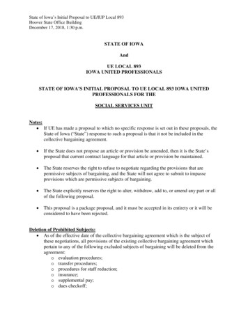
One of the simplest and most useful things we can do in a circuit is toreduce the complexity by combining similar elements that have series orparallel connections. Resistors, voltage sources, and current sources canall be combined and replaced with equivalents in the rightcircumstances.We start with resistors. In many situations, we can reduce complexresistor networks down to a few, or even a single, equivalent resistance.As always, the exact approach depends on what we want to know aboutthe circuit, but resistor reduction is a tool that we will use over and over.To set the stage, consider thecircuit at right. We might like toiSdetermine the power from thesource, which requires knowing V S–the current. Of course, we don’tknow the source currentinitially — we must nd it bynding the current owing inthe resistors.R1R31 kΩ470 ΩR22.2 kΩR41 kΩR5330 Ωseries/parallel combinations – 1fiG. Tuttle – 2022flfiSeries and parallel combinations
In the circuit, iS iR1, so our goaliSis to nd that. Set to work withKirchoff’s Laws. Since we don’t VSknow anything at the outset, we–will have to come up with enoughequations to have a simultaneousset that can be solved. vR1 – vR3 –iR1 iR3iR4vR2–– vR5 iR2 vR4–iR5KCL: iR1 iR2 iR3 ; iR3 iR4 iR5.KVL: VS – vR1 – vR2 0 ; vR2 – vR3 – vR4 – vR5 0.Using Ohm’s Law to write voltages in terms of currents and then ddlingaround to reduce the equations to a manageable set, we arrive at threeequations relating, iR1, iR2, and iR3. (We are skipping all the details here— there will be plenty of time for developing simultaneous equationslater.)iR1 iR2 iR3VS – iR1R1– iR2R2 0iR2R2 – iR1(R3 R4 R5) 0.series/parallel combinations – 2fifiG. Tuttle – 2022
Three equations, three unknowns.iR1 iR2 iR3VS – iR1R1– iR2R2 0iR2R2 – iR1(R3 R4 R5) 0.Soon enough, we will be adept at handling problems like this. For now,we will put our trust in Wolfram-Alpha (or something similar), and let itgrind out the answers.iR1 5.02 mA.iR2 2.26 mA.iR3 2.76 mA.Finally, iR1 iS and the power being delivered by the source isPS VS·iS (10 V)(5.02 mA) 50.2 mW.However, this business of nding three equations in three unknownsand solving all that seems a lot of work to determine one number in arelatively simple circuit. Is there a simpler way? Of course, the answer is“yes”.series/parallel combinations – 3fiG. Tuttle – 2022
Equivalent ResistanceThe original circuit was a singlesource with a network of resistorsiSattached. The resistor currents arerelated to the source current by KCL. VS –The resistor voltages are related to thesource voltage by KVL. The resistorcurrents are related to the resistorvoltages by Ohm’s Law.iSThen it seems reasonable that thesource voltage and source current VS–should be related by Ohm’s Law,meaning that there must be someequivalent resistance that representsthe cumulative effect of resistors inthe network:VSReq iSG. Tuttle – 2022R1R3R2R4R5Reqseries/parallel combinations – 4
The question is how to nd the equivalent resistance of the network.The general approach would be to apply a “test generator” to thenetwork. A test generator is a voltage or current source with a value thatwe can choose. For example, if we apply a test voltage source withvalue Vt, as shown below, then we can calculate the current, it, thatows into the network due to the applied source.R1R3itThe equivalent resistance VtVtR2R4–would then be Req .itR5In lab we could something similar by building the circuit, applying atest voltage, and measuring the result current. In lab, this process goesby a different name — it’s called “using an ohmmeter”.G. Tuttle – 2022series/parallel combinations – 5fiflEquivalent Resistance
Of course, we have already donethis. The earlier calculation isidentical to this test generator ideaif we set Vt 10 V. In thecalculation, we found the current tobe 5.02 mA. Then the equivalentresistance isR1itVt –R3R2R4R5Req 10 V / 5.02 mA 1.99 kΩ.However, this seems a bit pointless, because nding equivalent resistanceusing a test generator was as much work as nding the source current directly.In fact, it took one extra step to nd the equivalent resistance.But fear not. We can start with simple relationships for the equivalentresistance of series and parallel combinations. Then we can use series andparallel combinations to break down complex resistor networks and analyzethem in a piecemeal fashion. We will see that the equivalent resistance idea issimple to implement in most cases and can be a powerful method foranalyzing circuits. We will use it repeatedly as move through EE 201 and 230.fifiseries/parallel combinations – 6fiG. Tuttle – 2022
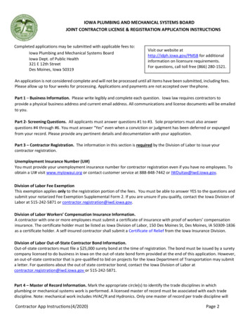
Series combinationResistors are in series, meaning that the same current ows in all. vR1 –R1itiR1Apply test voltage. ReqR2VtiR2De ne voltages–iR3and currents.R3 vR2–– vR3 By KCL: iR1 iR2 iR3 itBy KVL:Expected, since they are in series.Vt – vR1 – vR2 – vR3 0.Use Ohm’s law to write voltages in terms of currents.Vt iR1R1 iR2 R2 iR3R3 0Vt it R1 it R2 it R3 it (R1 R2 R3) 0VtReq R1 R2 R3itseries/parallel combinations – 7flfiG. Tuttle – 2022
Series combinationThe equivalent resistance of resistors in series is simply the sum of theindividual resistance.Req N m 1RmThe calculation is easy.The equivalent resistance is always bigger than any of the individualresistors, Req Rm.In fact, if one resistor is much much bigger than the rest, the equivalentresistance will be approximately equal to the one big resistor. Forexample, in the three-resistor string on the previous page, if R1 10 kΩ,R2 100 Ω, and R3 1 Ω, then Req 10.101 kΩ 10 kΩ.This is why we can ignore the resistance of wires in most cases.Consider a 1-kΩ resistor with its two leads. If the resistor body hasRB 1 kΩ and the wires are each Rw 0.01 Ω, the series equivalentresistance of the whole is resistor is then 1.00002 kΩ. In almost allpractical cases, the wire resistance is negligible.G. Tuttle – 2022series/parallel combinations – 8
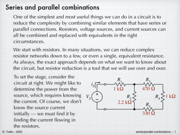
Parallel combinationResistors in parallel –– they all have the same voltage across.itReqR1R2R3Vt –iR1 vR1 iR2– vR2 iR3– vR3–Apply the test voltage.De ne voltages and currents.By KVL: vt vR1 vR2 vR3. Expected, since they are all in parallelBy KCL: it iR1 iR2 iR3.Use Ohm’s law to write iR in terms of vR.vR1 vR2 vR3it R1R2R3vtvtvt111it vt R1 R2 R3( R1 R2 R3 )fiG. Tuttle – 2022it1111 Req vt R1 R2 R3series/parallel combinations – 9
Parallel combinationThe inverse of the equivalent resistance is equal to the sum of theinverses of all the resistance in the parallel combination.N11 RmReq m 1The equivalent resistance will always be smaller than the resistance ofany individual branch: Req Rm for all m.If one resistor is much smaller than all other resistors in the parallelcombination, (so that its inverse is much bigger), then the equivalentresistance will be approximately equal to that of the smallest resistor.For example, if the three parallel resistors from the previous page hadvalues of R1 10 kΩ (1/R1 10–4 Ω–1), R2 100 Ω (1/R2 10–2 Ω–1), andR3 1 Ω (1/R3 1 Ω–1), then Req 0.99 Ω 1 Ω (1/Req 1.0101 Ω–1).In fact, if we place a wire (Rw 0) in parallel with other resistors, theequivalent resistance approximately zero — the wire has shorted outeverything else.G. Tuttle – 2022series/parallel combinations – 10
Since the calculation for parallel resistors, with the need for inverses, canbe a bit messy, there are some short-cuts that can used for special cases.If there are only two resistors in parallel:R2R1R1 R2111 Req R1 R2 R1R2 R1R2R1R2R1R2Req (Product over sum, which might be easier to compute.)R1 R2Two identical resistors, R1 R2 R:R2RReq (e.g. Two 1-kΩ resistors in parallel gives 0.5 kΩ.)R R2N identical resistors in parallel (extending the idea):1RReq 1 1 .N 1RRRIf one resistor is much smaller than the rest (R1 Rm) (to re-emphasize)Req G. Tuttle – 20221R1 1R21 1RN R1 If R1 0 (short circuit), then Req 0.series/parallel combinations – 11
Breaking down networks using series and parallelBut not all circuits are simplecombinations of series or parallelresistors. The initial example circuitclearly has some things that are inseries and some elements that havea parallel-type connection.R1R3470 ΩR41 kΩReqR22.2 kΩ1 kΩR5330 ΩThe trick is to break the circuit into smaller pieces that are purely seriesor parallel, nd the equivalent of that piece and insert that back into theoriginal circuit, which will now be simpler. Then nd another series orparallel combination that can be simpli ed. Through a sequence ofsteps, it may be possible to reduce even complex combinations to asingle equivalent resistance.R3For the circuit above, we can start byrecognizing that the R3 - R4 - R5 seriescombination can be reduced:R345 R3 R4 R5 1.8 kΩ.R345470 ΩR41 kΩR5330 Ωfifiseries/parallel combinations – 12fiG. Tuttle – 2022
R1Insert the single R345 resistor backinto the original circuit. Now, quiteobviously, R2 is in parallel with R345.Calculate the equivalent resistance ofthe parallel combination. Using thetwo-resistor formula:1 kΩReqR2345R2R3452.2 kΩ 1.8 kΩR2R3452.2 kΩ 1.8 kΩR2 R345(2.2 kΩ) (1.8 kΩ)R2345 990 ΩR2 R345 (2.2 kΩ) (1.8 kΩ)Insert the R2345 equivalent back intowhat is left of the original circuit.Now, we easily calculate Req as theseries combined of R1 and R2345.ReqR11 kΩR23450.99 kΩReq R1 R2345 1 kΩ 0.99 kΩ 1.99 kΩ.G. Tuttle – 2022Calculating source power is now trivial.series/parallel combinations – 13
The equivalent resistance “method”So we have a method for trying to nd equivalent resistances withouthaving to resort to messy combinations of Kirchoff’s Laws.1. Identify the pair of nodesbetween which we want to ndequivalent resistance. Peer into itOhm’s eyewith “Ohm’s eye”.2. Starting at the opposite end ofthe network, identify series andparallel combinations that can bereduced using the simple formulas.3. Repeat with another series orparallel combination to furthersimplify the s/parallel combinations – 14fiG. Tuttle – 2022R1
4. Continue the simpli cationprocess, one series or parallelcombination at a time, until thenetwork is reduced to a singleresistor. (Or until the remainingnetwork is trivial.)R1R2345ReqIt is not necessary to insert numbers at each step — we could expressthe results using symbols and then insert numbers at the end, if needed.For the example, the equivalent resistance expressed in symbols:R2 (R3 R4 R5)R2 R345Req R1 R2345 R1 R1 R2 R345R2 R3 R4 R5With practice, many circuits can be simpli ed by inspection (i.e. in ourheads). We might even be able to calculate the values in our heads.Not all resistive networks can be reduced using series / parallelcombinations. Consider the bridge circuit that was one of the Kirchoff’sLaws practice problems — the bridging resistor is not in series orparallel with any other resistors and so there are no simpli cations.fifiseries/parallel combinations – 15fiG. Tuttle – 2022
Example 1Find the equivalentresistance looking intothe indicated port of the“ladder network” shown.Req1. Starting at the “far end”,we see that R5 and R6 arein series.330 Ω330 Ω330 ΩR1R3R5R2680 ΩR4680 Ω330 Ω330 ΩR1R3R2680 ΩR4680 ΩR6680 ΩR561010 ΩR56 R5 R6 1010 Ω.2. R4 is in parallel with R56.R456 (1/R4 1/R56 )–1 407 Ω.G. Tuttle – 2022330 Ω330 ΩR1R3R2680 ΩR456407 Ωseries/parallel combinations – 16
Example 1 (cont.)330 ΩR13. R3 and R456 are in series.R2680 ΩR3456 R3 R456 1010 Ω.R3456737 Ω330 Ω4. R2 is in parallel with R3456.R23456 1R21 1ReqR23456354 Ω 354 ΩR34565. Finally, Req is the seriescombination of R1 and R23456.Req 330 Ω 354 Ω 684 Ω.G. Tuttle – 2022R1Req(OK — thesubscriptingthing is getting abit ridiculous.)684 Ωseries/parallel combinations – 17
Example 2Find the equivalent resistance looking into the indicated port of thecircuit shown below.R547 ΩR6ReqR133 ΩR318 Ω100 ΩR268 ΩR482 ΩR9R7220 ΩR839 Ω68 ΩR1068 ΩAt rst glance, this looks very dif cult, but it’s not so bad. We can pickit apart piece by piece. Start by noting that R7 is in parallel with R8.fiG. Tuttle – 20221R7 1R8 33.1 Ωseries/parallel combinations – 18fiR78 1
Example 2 (cont.)Similarly, R5 is in parallel with R6 and R9 is in parallel with R10.R56 1R51 1R6 32.0 ΩR910 R56R133 ΩR318 ΩR268 ΩR482 Ω1R91 1R10 34 Ω32 ΩR7833 ΩR91034 ΩNext, we note that there are several series combinationsR1 in series with R2 : Ra R1 R2 101 ΩR3 in series with R4 : Rb R3 R4 100 ΩR56, R78, and R910 all in series : Rc R56 R78 R910 99 ΩG. Tuttle – 2022series/parallel combinations – 19
Example 2 (cont.)Finally, we see that the equivalent resistance is just the parallelcombination of Ra, Rb, and Rc.ReqReq Ra101 Ω1RaRb100 Ω1 1Rb 1RcRc99 Ω 33.3 ΩNot that bad.G. Tuttle – 2022series/parallel combinations – 20
Example 3Find the equivalent resistance at the indicated port in the circuit below.R1R31 kΩ10 kΩReqR21.5 kΩR5470 ΩR45.6 kΩThere are a couple of interesting things going on here. First, we see some“diagonal” resistors. Secondly, we see a “dangling” resistor, R5, which is notconnected to anything on one side.First, the diagonal resistors are essentially an optical illusion — current andvoltage do not care about the spatial orientation of the components. We canre-draw the circuit in the more familiar grid-like arrangement, with no changein how the circuit behaves.R1ReqG. Tuttle – 2022R3R2R5R4series/parallel combinations – 21
Example 3 (cont.)Now, about the dangling resistor. Since the right-hand side of R5 is“open circuited”, we can view R5 as being in series with a resistor withvalue approaching in nity. (An open circuit is essentially a resistor withR .) A series combination of any nite resistor in nity is alsoin nity. (Mathematicians are cringing now.) So essentially, the danglingR5 is the same as an open circuit — in principle, we could have left itoff entirely with no change in equivalent resistance. (In the future, wewill see a number of situations where there are dangling componentslike this, and we need to know how to handle them.)R5R5Roc( )Roc R5( )fifiseries/parallel combinations – 22fifiG. Tuttle – 2022
Example 3 (cont.)Now that we straightened out the diagonals and trimmed off thedangler, the circuit looks familiar and simpleReqR1R31 kΩ10 kΩR21.5 kΩR45.6 kΩAnd the calculation is straight-forward:R34 R3 R4 15.6 kΩ1R234 1 1.37 kΩ1 RR234Req R1 R234 2.37 kΩG. Tuttle – 2022series/parallel combinations – 23
Example 3aSame circuit, but now nd the equivalent resistance looking from theother end.R1R3R51 kΩ10 kΩ470 ΩR21.5 kΩThe previous comments aboutthe diagonals and thedangling resistor apply, exceptthat now R1 is the dangler.ReqR45.6 kΩR3R2R5R4We start at the “far end” and work towards the eyeball.R23 R2 R3 11.5 kΩR234 1R23 1R4 3.77 kΩReq R5 R234 4.24 kΩfiG. Tuttle – 20221series/parallel combinations – 24
Voltage sources in series.Consider the simple series circuit at right. We canwrite a KVL equation around the loop:VS1 – vR1 – VS2 – vR2 0.R1VS1 –– vR2 VS1 – VS2 – vR1 – vR2 0. –VS2VS1 –VS1 – VS2 – iR1·R1 – iR2·R2 0.VS12 –R12VS12 VS1 VS2R12 R1 R2series/parallel combinations – 25flG. Tuttle – 2022 vR1–– vR2 Since the same current ows in all components inthe series string, iS1 iS2 iR1 iR2 iS.We know that we can combine series resistors. Itappears that we can also combine series voltagesources: VS12 – iS R12 0.R1R2Now we can use Ohm’s Law to writeVS1 – VS2 – iS (R1 R2) 0. VS2–R2Addition and subtraction are commutative, so wecan re-arrange the ordering in the equation.This would imply that we can re-order thecomponents in the circuit. The re-ordered circuit ismust behave the same as the top circuit. vR1 –
Voltage sources in series.The little exercise on the previous slide show us important ideas aboutseries connections.1. The ordering of components in the series string is irrelevant — we canre-order the voltage sources and resistors to suit our needs.2. Just like resistors in series, we can combine voltage sources in seriesand treat them as a single source.The idea of putting voltage sources in series should be familiar to most —in electronic gadgets it is common to connect several 1.5-V batteries inseries to create 3-V or 4.5-V or 6-V or whatever voltage is needed topower a circuit.When combining series voltage sources, there might some uncertaintyabout whether to add or subtract the values (particularly for neophytes).The ambiguity can always removed by writing a proper KVL equationaround the loop. Kirchoff will make it clear whether to add to or subtract.G. Tuttle – 2022series/parallel combinations – 26
Current sources in parallel.Consider the simple circuit at right. We canIS1write a KCL equation at the top node:IS2R1R2iR1IS1 – iR1 IS2 – iR2 0.iR2Addition and subtraction are commutative, sowe can re-arrange the ordering in the equation.IS1 IS2 – iR1 – iR2 0.This would imply that we can re-order thecomponents in the circuit. The re-orderedcircuit must be identical to the top circuit.We can use Ohm’s Law to writevR1 vR2IS1 IS2 0R1R2IS1IS2R1R2iR1IS12iR2R12All the components have the same voltage across, vIS1 vIS2 vR2 vR2 vS,We know that we can combine the parallel resistors, and it appears that wecan combine the current sources as well. 1vSvSvS11IS1 IS2 0 IS12 0IS12 IS1 IS2 R12 ( R1 R2 )R1 R2R12G. Tuttle – 2022series/parallel combinations – 27
Current sources in parallel.The little exercise on the previous slide show us to important ideas aboutparallel connections.1. The ordering of components in the parallel arrangement is irrelevant— we can re-order the parallel current sources and resistors to suit ourneeds.2. We can combine current sources in parallel and treat them as a singlesource.When combining parallel current sources, there is often some uncertaintyabout whether to add or subtract the values. The ambiguity can alwaysremoved by writing a proper KCL equation at the node where they areconnected. Kirchoff will make it clear whether to add to or subtract.G. Tuttle – 2022series/parallel combinations – 28
Example 4 –Below is a conglomeration of sources and resistors. Simplify the circuitby combining the series and parallel components.10 Ω1.5 VR222 ΩR1 VS1–12 VVS2R447 ΩR30.5 AR515 ΩIS20.25 AIS3R668 Ω 0.75 A –VS3IS16V33 ΩThree resistors in series on the left: RL R1 R2 R3 65 ΩThree sources in series on the left: VL VS3 VS1 – VS2 14.5 VThree resistors in parallel on the right:RR 1R( 4 R5 1 1 1R6 ) 9.74 ΩThree sources in parallel on the right:IR IS1 – IS2 IS3 1 A.G. Tuttle – 2022RLVL14.5 V –65 ΩRR9.7 ΩIR1Aseries/parallel combinations – 29
Voltage sources in parallel, current sources in seriesFrom a theoretical point of view, these combinations are not allowable. Theylead to untenable conundrums with Kirchoff’s Laws. VS1–12 V VS2–6VKVL: VS1 – VS2 6 V 0!! Yikes!IS12AIS2 1 AKCL: IS1 IS2 : In Out!! Yikes!Rw small!So in 201 circuits, we avoid these. However, everyoneknows that sometimes voltage sources are connected to parallel — charging a battery is essentially requiresVS1VS2––connecting one source to another. If there were no otherconsiderations, then the resistance of the wire (which wegenerally ignore in 201) comes into play.VS1 VS2i Rw BIG!If we connect two random batteries together (or short out a battery —VS2 0), bad things may happen. A practical battery charger will have somemeans to limit current. In fact, it may actually be current source.G. Tuttle – 2022series/parallel combinations – 30
G. Tuttle - 2022 series/parallel combinations - 3 Three equations, three unknowns. i R1 i R2 i R3 V S - i R1R 1- i R2R 2 0 i R2R 2 - i R1(R 3 R 4 R 5) 0. Soon enough, we will be adept at handling problems like this.