Transcription
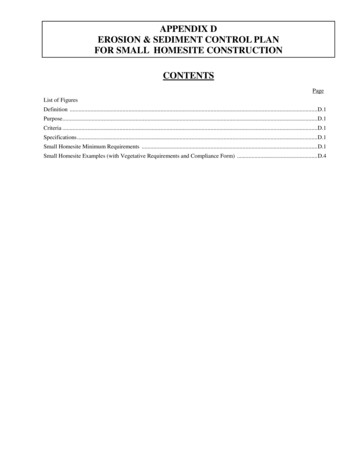
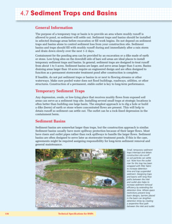
4.7 Sediment Traps and BasinsGeneral InformationThe purpose of a temporary trap or basin is to provide an area where muddy runoff isallowed to pond, so sediment will settle out. Sediment traps and basins should be installedin selected drainage areas before excavation or fill work begins. Do not depend on sedimenttraps and basins alone to control sediment loss from your construction site. Sedimentbasins and traps should fill with muddy runoff during and immediately after a rain stormand drain down slowly over the next 1–2 days.Containment for the ponding area can be provided by an excavation or a dike made of earthor stone. Low-lying sites on the downhill side of bare soil areas are ideal places to installtemporary sediment traps and basins. In general, sediment traps are designed to treat runofffrom about 1 to 5 acres. Sediment basins are larger, and serve areas larger than 5 acres. Basinsdraining areas larger than 10 acres require an engineered design and are often designed tofunction as a permanent stormwater treatment pond after construction is complete.If feasible, do not put sediment traps or basins in or next to flowing streams or otherwaterways. Make sure pooled water does not flood buildings, roadways, utilities, or otherstructures. Construction of a permanent, stable outlet is key to long-term performance.Temporary Sediment TrapsAny depression, swale, or low-lying place that receives muddy flows from exposed soilareas can serve as a sediment trap site. Installing several small traps at strategic locations isoften better than building one large basin. The simplest approach is to dig a hole or builda dike (berm) of earth or stone where concentrated flows are present. This will help todetain runoff so sediment can settle out. The outlet can be a rock-lined depression in thecontainment berm.Sediment BasinsSediment basins are somewhat larger than traps, but the construction approach is similar.Sediment basins usually have more spillway protection because of their larger flows. Mosthave risers and outlet pipes rather than rock spillways to handle the larger flows. Sedimentbasins are often designed to serve later as stormwater treatment ponds. If this is the case,agreements might be required assigning responsibility for long-term sediment removal andgeneral maintenance.Small, temporary sedimenttraps intercept and detainconstruction site runoffso soil particles can settleout. Note how the outletriser for this trap has beenwrapped with filter fabricto increase detentiontime and trap suspendedsediment. Designing trapsand basins with long flowpaths between the inletand outlet also helps toincrease sediment removalefficiency by extending thedetention time. Where spacerestrictions prevent longbasin designs, barriers placedin the basin can lengthendetention times by creatinga serpentine flow pathbetween the inlet and outlet.136Technical Specifications for BMPs
4.7 Sediment Traps and Basins4.7.1 Temporary Sediment (Silt) TrapsSimple traps or “checks” with rock bermcontainment structures can be installedas needed by field personnel with orwithout specific notations on plandocuments. Standard notes on plansshould call for installation of temporarytraps in concentrated flow areas subjectto rutting on an as-needed basis. Makesure containment berms are designed foroverflow in the center of the berm, toprevent sidecutting and bypasses. Installtraps in a series to control sediment fromlarge upland areas.DefinitionA temporary sediment or silt trap is formed by excavation or by constructing a smallembankment of stone, stone-filled bags, or other material to retain sediment. Sedimenttraps are considered temporary structures and often placed at the site on an as needed basisby field personnel. They should not be placed in flowing streams.PurposeSediment traps pond and settle sediment from muddy runoff. Traps are used wherephysical site conditions or other restrictions prevent other erosion control measures fromadequately controlling erosion and sedimentation. Sediment traps can be used downslopefrom construction operations that expose areas to erosion.Design CriteriaBermed sediment traps confined by rock, rock-filled fiber bags, or other material arepreferred over excavated traps or those with soil berms. Traps are placed in converging flowareas (i.e., where ruts or washouts can form) or in ditches, where they are often called ditchchecks or check dams. All traps are sized according to a design volume of 3,600 cubic feetper disturbed acre in the upstream drainage area. Multiple sediment traps constructed in aseries are needed when the storage volume of each cannot meet this design requirement.Sediment traps are generally used to treat a drainage area of 5 acres or less. When thetotal drainage area to a single structure exceeds 10 acres, an engineered sediment basinis necessary. Traps cannot be placed in blue-line streams or other regulated waters unlessspace limitations or design limitations provide no other feasible option. A USACE CleanWater Act (CWA) section 404 permit is required in these cases. Sediment traps must becleaned out before they are half full of sediment.KYTC Silt Trap Types A, B, and CThe KYTC specifies three types of temporary sediment or silt traps. Type A is an excavatedbasin with or without a soil berm constructed in a ditch or drainageway. Type B is oneor more small berms of rock (KYTC No. 2 or shot rock) placed in a drainageway or ditch,with a geotextile underliner covered by 4 inches of KYTC No. 4 stone. A 12-inch overflowdepression appears in the middle of the berm(s). Type C traps are berms constructed ofporous fabric bags filled with crushed aggregate (e.g., KYTC No. 57), placed individually orin a series to create small ponding dams around drop inlets, curb inlets, or to form checkdams in a drainageway or ditch.Kentucky Construction Site BMP Planning and Technical Specifications Manual137
General Construct traps of rock (KYTC No. 2 mixed with smaller stone), rock-filled fiber bags,or use approved commercial sediment trap products installed and spaced accordingto manufacturer’s instructions. Site sediment traps in areas where they can be maintained (i.e., sediment removed). Set traps back from property lines or water bodies as much as possible. Do not site sediment traps at culvert or pipe outlets if possible. Minimum sediment storage capacity is 3600 cubic feet per acre of upland areadrained by the trap. Where space restrictions exist, install multiple traps in a series atleast 50 feet apart. Maximum drainage area is 5 acres. Basin flow length should be at least two times the flow width. Recommended trap depth for open areas is 2 feet at the inlet and 4 feet at the outlet. Trap height must be 1.5 feet minimum in ditches, 3–5 feet in open area drainageways. Trap berm width at base must be sufficient to support 2H:1V berm. Trap length must be sufficient to tie into upper banks in ditches or high enough toprevent side bypasses in drainageways. Overflows must be in the center of the berm. Construct the trap, seed and stabilize before clearing and grading work begins.Embankment requirements Maximum height of 5 feet. Maximum inside and outside slopes of 2:1. Side slopes, containment berms, and inflowing ditches should be seeded andmulched or blanketed as soon as possible after construction.Outlet requirements The outlet must consist of an overflow spillway wide made of stone (KYTC No. 2minimum).Construction Specifications Construct initial series of sediment traps before general site clearing and grading. The area to be excavated or ponded must be cleared of all trees, stumps, roots, brush,boulders, and debris. All topsoil containing excessive amounts of organic matter mustbe removed. Seeding, fertilizing, and mulching of the material taken from the excavation mustcomply with the applicable soil stabilization sections of this manual. Any material excavated from the trap must be uniformly spread to a depth notexceeding 3 feet and graded to a continuous slope away from the trap. Field-approved installations should be noted on weekly inspection reports and onplan documents within 7 days.138Technical Specifications for BMPs
Inspection and MaintenanceThe trap must be inspected weekly and after every rainfall greater than one-half inch.Sediment must be removed from the trap before the capacity is reduced to 50 percent ofthe design volume. Plans for the sediment trap must indicate the methods for disposing ofsediment removed from the pond.Temporary sediment traps are removed upon stabilization or cover of the upland drainagearea with vegetation, pavement, and so on. The trap area should be graded, seeded, andmulched or blanketed. Excess sediment should be spread and stabilized where it will notenter the drainage system.Make sure overflow outlet or riser isdesigned for maximum detention times.Note the rock berm around riser, whichensures maximum detention for muddyflows after small storms.Design sediment traps withlong flow paths if possible.Make sure overflow area isprotected with rock or otherarmoring. For best results,seed trap and upland areasimmediately after construction.Good trap placementand performance; poormaintenance. Removeaccumulated sedimentbefore trap is half full.Spread material removedin a vegetated uplandarea or other site where itwill not wash into nearbysurface waters.In areas where space is restricted, use multiple traps in a series to meet thedesign goal of 3600 cubic ft per acre of upland drainage. Get to final grade,seed and mulch as soon as possible to reduce trap maintenance and upkeep.Kentucky Construction Site BMP Planning and Technical Specifications Manual139
140Technical Specifications for BMPs
Kentucky Construction Site BMP Planning and Technical Specifications Manual141
142Technical Specifications for BMPs
4.7 Sediment Traps and Basins4.7.2 Sediment (Detention) BasinsWell-stabilized detention basin witherosion control blankets protectingsidewalls during grass seed germination.Note the temporary stone berming infront of outlet, which increases detentiontime and promotes maximum settling ofsoil particles. Design of this basin could begreatly improved by adding a temporarybaffle or barrier between the inlet andoutlet, which would force inflows fromthe culvert around the baffle. The longerflow path and settling time wouldimprove soil removal.DefinitionA sediment basin is a pond created by excavation and construction of an embankment anddesigned to retain or detain runoff sufficiently to allow excess sediment to settle out.PurposeThe sediment basin is intended to collect and store sediment from sites that are cleared orgraded during construction or for extended periods of time before permanent vegetationis reestablished or before permanent drainage structures are completed. It is intendedto intercept and trap sediment before it leaves the construction site. Some basins aretemporary, with a design life of 12 to 18 months, and are to be maintained until the sitearea is permanently stabilized. Basins that will serve as permanent stormwater treatmentponds often require modified outlet risers during construction to ensure adequate pondingtimes and sediment removal.Basins should be located at the stormwater outlet from the site, not in any natural orundisturbed stream. Use of temporary dikes, pipes or channels might be necessary to divertrunoff from disturbed areas into the basin and to divert runoff originating from undisturbedareas around the basin.Design CriteriaSediment basins must be designed by a professional engineer licensed in Kentucky. Thebasin should be designed using SEDCAD or other computer program. The design criteriaare listed below:GeneralSite sediment basins where they will provide the best treatment (longest flow path betweeninlet and outlet, longest settling times) for the greatest area of the site. It is recommendedthat dams be located in a natural drainageway in a deep constriction that has a wide areaupstream for ponding detained stormwater. Do not locate dams where a failure would result in severe property damage or dangerto human life. Sediment basins should be designed or modified to drain down slowly for 2–4 daysafter a storm event. Modify the outlet if necessary to achieve the maximum detentiontime.Kentucky Construction Site BMP Planning and Technical Specifications Manual143
Minimum design storage capacity is 3600 cubic feet per acre of upland area drained.The maximum capacity for the impoundment must not exceed 10 acre-feet. If moreimpoundment capacity is needed, install basins in a series or site them to intercepttributary drainage areas. Construction phase performance goal is to reduce the total suspended solids by80 percent for the 10-year, 24-hour storm, or provide a detention time of 24 to 48hours for the 10-year, 24-hour storm. Minimum drainage area is 5 acres; the maximum drainage area is 120 acres. Basin flow length should be at least two times the flow width; the longer, the better.Baffles constructed of filter fabric and metal posts can be used inside the basin tocreate a longer (e.g., serpentine) flow path between inlet(s) and the outlet. Construct the basin before clearing and grading work begins. Basins, side slopes, berms, inlets, and downstream outlet channels must be seededand mulched or blanketed immediately after construction. Basins that drain more than 10 acres can be designed as retention (rather thandetention) basins (i.e., wet ponds). Design outlet to drain top of the pool farthest awayfrom muddy inflows. Incorporating a sediment collection forebay is recommended toaid in maintenance.Embankment requirements Dam height should not exceed 20 feet Maximum inside and outside slopes of the dam must be 3H:1V Minimum 1 foot freeboard during the 100-year, 6-hour storm Antiseep collars around discharge pipe are required Minimum top width of the dam must be 12 feetPrincipal spillway (riser and barrel) requirementsUse a subsurface drain, a solid riser pipe,or both, with sufficient dewatering holes toprovide sufficient detention time. Risers withone-half inch holes every 3 to 6 inches apartare recommended. No large holes or slots should appear inthe lower two-thirds of the riser. Riserswith large openings can be modified asdescribed below or wrapped with filterfabric to cover lower openings during theconstruction period. During construction, risers should bemodified with an inlet protection dike,pile of stone at the riser base, or otherstructure to provide longer ponding timesfor small flow events. Operational design goal is to reduce thepeak flow to predevelopment levels forthe 2-year and 10-year, 24-hour storms.144Technical Specifications for BMPsKY Division of Water DamSafety RequirementsThe sediment basin might haveto be designed in accordancewith dam safety requirements ofthe KY Division of Water. A damis defined as any impoundingstructure that is either 25 feetin height, measured from thedownstream toe to the crest,or has a maximum impoundingcapacity of 50 acre-feet ofwater. Structures that do notmeet these criteria but have thepotential to cause significantproperty damage or pose athreat to loss of life in thedownstream area are regulatedin the same manner as dams.
Minimum diameter of pipe outlet is 12 inches; anti-vortex baffle and trash rack arerequired Minimum one foot freeboard required from top of riser to crest of emergency spillwayEmergency spillway requirements Designed to pass the 100-year, 6-hour post development peak flow Crest elevation at least one foot above the tip of the riser pipe Minimum one foot freeboard during the 100-year, 6-hour storm to the top of theembankment Rock used for the emergency spillway must be KYTC No. 2 or larger, depending onflow volumes and spillway slope (see sections on rock-lined channels and outletstabilization energy dissipator) Emergency spillway energy dissipator must be extended at least 4 feet beyond the toeof the damConstruction Specifications Construct the basin by excavating or building an embankment dike before anyclearing or grading work begins. Areas under the embankment and any structural works must be cleared, grubbed andstripped of any vegetation and rootmat as shown on the erosion and sediment controlplan. To facilitate cleanout and restoration, the basin area must be cleared, grubbed andstripped of any vegetation. A cut-off trench must be excavated along the centerline of the earth fillembankments. The minimum depth must be 2 feet. The cut-off trench must extendup both abutments to the riser crest elevation. Fill material for the embankment must be clean, low-permeability, mineral soil free ofroots, woody vegetation, oversized stones, rocks, or other objectionable material. Fill material must be placed in 6 inch lifts, continuous layers over the entire lengthof the fill. Compacting must be obtained by routing the hauling equipment overthe fill so that the entire surface of each layer of the fill is traversed by at least onewheel or tread track of the equipment or by the use of a compactor. Each layer mustbe compacted to 95 percent of maximum density and /– 2 percent of optimummoisture content. The embankment should be constructed to an elevation of 10 percent higher thanthe design height to allow for settlement if compacting is achieved with haulingequipment. If compactors are used for compacting, the overbuild may be reduced tonot less than 5 percent. The principle spillway riser must be securely attached to the discharge pipe bywelding all around. All connections must be watertight. The pipe and riser must be placed on a firm, smooth soil foundation. The connectionbetween the riser, and the riser base must be watertight. Pervious materials such assand, gravel, or crushed stone must not be used as backfill around the pipe or antiseep collars.Kentucky Construction Site BMP Planning and Technical Specifications Manual145
The fill material around the pipe spillway must be placed in 4-inch layers andcompacted under the shoulders and around the pipe to at least the same density asthe adjacent embankment. A minimum of 2 feet of compacted backfill must be placedover the pipe spillway before crossing it with construction equipment. Risers might require a rock berm or other flow restrictor during the constructionphase to ensure that muddy flows are detained sufficiently to promote settling ofsediment. Steel base plates must have at least 2.5 feet of compacted earth, stone, or gravel overthem to prevent flotation. An emergency spillway is required, and must not be installed in fill. Appropriateoverflow channel lining and energy dissipator must be constructed. Baffles, if used, must be constructed of 4 inch by 4 inch posts and of 4 foot by 8 foothalf-inch exterior plywood. The posts must be set at least 3 feet into the ground, nofarther apart than 8 feet center to center, and must reach a height 6 inches below theriser crest elevation. Silt fencing with metal posts can also be used if flow velocitiesin the basin are low and ponding heights during the 2-year, 24-hour storm will notexceed 5 feet. The embankment, emergency spillway, incoming channels, and other site featuresmust be stabilized with vegetation and mulched or blanketed immediately followingconstruction. Construction operations must be carried out in such a manner that erosion and waterpollution will be minimized. Local and state requirements must be met concerning fencing and signs warning thepublic of hazards of soft sediment and floodwater.Inspection and MaintenanceInspect the sediment basin weekly and after each rainfall greater than one-half inch. Ifincoming flows are exiting the basin quickly because of large holes in the outlet, modify thelower portion of the riser with a stone berm, filter fabric, or other flow restrictor that retainsincoming flows for at least 12–24 hours. All damages caused by soil erosion or construction equipment must be repairedbefore the end of each working day. Remove sediment when the sediment storage zone is half full. This sediment mustbe placed in such a manner that it will not erode from the site. The sediment mustnot be deposited downstream from the embankment or in or adjacent to a stream orfloodplain. When temporary structures have served their intended purpose and the contributingdrainage area has been properly stabilized, the embankment and resulting sedimentdeposit must be leveled or otherwise disposed of according to the approved erosionand sediment control plan. If the sediment basin is designed to function as a permanent stormwater treatmentpond, the basin and riser will be configured to that mode upon stabilization of theupland drainage area. Temporary flow restrictors on risers and other constructionphase modifications must be removed.146Technical Specifications for BMPs
This is a well-constructed sediment basin. Notethe rock flow restricter around outlet riser, whichfilters and detains inflows. Basin sidewalls should beseeded immediately after construction.For best results, seed basin sidewalls and upland drainage areasas soon as possible. Make sure outlet structure does not allowrapid flow through the basin—use a rock berm, filter fabric, orother means to maximize ponding and detention time.The flow path through this basinhas been lengthened by usingfilter fabric baffles constructedto create a serpentine flow path.Note the rock pile around outletriser to maximize detention andgrass on sidewalls.This outlet riser intakehole has been modifiedwith a “half round”section of pipe with1-inch holes on 6-inchcenters and rock berm.This temporary dikeprovides additionaldetention during theconstruction phase, whichimproves soil removal.This shows a very well designeddetention basin, featuring longflow path between inlet and outletand V-notched outlet riser, whichprovides longer detention timesfor low flow events while stillaccommodating larger storms.Operation of this basin during theconstruction phase, however, isvery poor. Note the lack of grasson sidewalls; no temporary dikein front of the outlet. This basinappears to be filling rapidly andrequires sediment removal.Kentucky Construction Site BMP Planning and Technical Specifications Manual147
148Technical Specifications for BMPs
Kentucky Construction Site BMP Planning and Technical Specifications Manual149
4.7 Sediment Traps and Basins4.7.3 Dewatering DevicesThis shows a dewatering sedimentfilter bag (center) in use at residentialconstruction site. Muddy waterpumped into the bag is physicallyfiltered, with clear water passingthrough the bag fabric. Pumpingmuddy, unfiltered water directly intocurb drains (center left) or surfacestreams constitutes a direct KPDESpermit violation.DefinitionDewatering is the pumping of stormwater or groundwater from excavation pits or trenches.The sediment-laden water must be pumped to a dewatering structure for sediment removalbefore it is discharged off-site.PurposeThe purpose of a dewatering device is to remove sediment from the water before it isdischarged off-site.Design CriteriaDewatering operations should not discharge to a ditch, pipe, or other conveyance thatleads to a regulated water body (e.g., stream, river, wetland, lake) except as authorized by aKPDES permit.There are several types of dewatering structures or devices that can be used. A flat, wellstabilized, vegetated area can serve as a filtering structure if it can withstand the velocityof the discharged water and infiltrate or assimilate it without erosion. The minimum filterradius or length must be at least 75 feet.It is recommended that sediment basins or temporary sediment traps receive sedimentladen water from bore pits and trenches. This will ensure that the 80 percent trappingefficiency goal will be upheld. Take special care to ensure that pumping this water does notcause the sediment control structure to fail. Also take care at the outlet of the hose from thepump to ensure that erosion does not occur because of high concentrated flows.Another option is to use an infiltration trench—a shallow, excavated trench back-filledwith stone—to form a reservoir. This reservoir can contain subsurface drainage pipe or juststone. This trench allows water to filter through the stone and then be diverted to a suitabledischarge point. The soils and the depth to the water table must be suitable for this sort ofdewatering. Typical trench depths range from 2 to 8 feet. The stone fill material consists ofwashed aggregate 1.5 to 3 inches in diameter.Other methods that can be used include a portable sediment tank, a silt fence pit, or acommercial sediment filter bag or sock. The structure must be sized to allow pumped waterto flow through the structure without overtopping.150Technical Specifications for BMPs
Construction SpecificationsSee the specifications in this manual for sediment traps and basins. Follow themanufacturer’s recommendations for commercial products.Inspection and MaintenanceInspect the dewatering structure or device frequently to ensure that it is functioningproperly and not overtopping. Accumulated sediment should be spread out on site andstabilized, or disposed of off-site.Silt fence enclosures and commercial sediment filters will likely require cleaning to removefine particles and restore performance. This can be done with a stiff brush when the filter isdry, or via other manufacturer’s recommendations.Containment structuresfor sediment-laden watercan be made of rock orfilter fabric. Standard notesshould require monitoring tomake sure the containmentstructure is not breachedduring dewateringoperations.Large bags or socks made of filterfabric provide excellent sedimentremoval and are extremelyversatile. Site filtration structuresaway from surface waters ifpossible. Dispose of sedimentcollected in a flat vegetated areaor other site where it will notwash into surface waters.Large sediment filter bag in operation.Note the row of straw bales around thebag providing additional treatment forclarified flow oozing out of the bag. Asilt fence could also be used.When dewatering sediment orother ponds, wait until severaldays after the last rain if possibleto allow for settling of sediments.Pump from the upper portion ofpond, where water is clearer.Kentucky Construction Site BMP Planning and Technical Specifications Manual151
checks or check dams. All traps are sized according to a design volume of 3,600 cubic feet per disturbed acre in the upstream drainage area. Multiple sediment traps constructed in a series are needed when the storage volume of each cannot meet this design requirement. Sediment traps are generally used to treat a drainage area of 5 acres or less.