Transcription
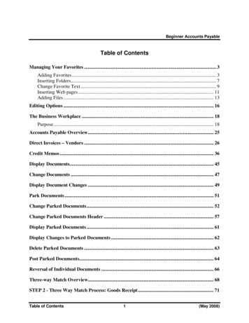
DWIRE HALLUniversity of Colorado at Colorado SpringsTABLE OF CONTENTSDIVISION 15 - MECHANICALSECTION NO.SECTION 15891159101593215933159711597515990Basic Mechanical RequirementsMech/Elec. Requirements for Mechanical EquipmentMechanical Systems Fire StoppingBasic Piping Materials and MethodsValvesPiping SpecialtiesPipe Expansion JointsMeters and GagesSupports and AnchorsMechanical IdentificationVibration ControlMechanical InsulationFire ProtectionWater Distribution PipingDrainage and Vent SystemsPlumbing FixturesWater TreatmentWater HeatersGlycol SystemsRefrigeration SpecialtiesHVAC PumpsBoiler AccessoriesBreechings, Chimneys and StacksCondensing UnitsScroll ChillersTerminal UnitsAir Handling FansAir Handling UnitsAir CleaningMetal DuctworkDuctwork AccessoriesAir Outlets and InletsAir TerminalsDirect Digital ControlsSequence of OperationTesting, Adjusting and BalancingDIVISION 16 - ELECTRICALSECTION NO.SECTION Basic Electrical RequirementsRacewaysWires and CablesCabinets, boxes and EnclosuresElectrical Connections for EquipmentWiring DevicesSupporting DevicesElectrical IdentificationSwitchboards03/29/06
DWIRE HALLUniversity of Colorado at Colorado ardsOvercurrent Protective DevicesTransfer SwitchesPoles and StandardsLightingEmergency LightingDiesel Generator SetsLightning Protection SystemsTransient Voltage Surge Suppression (TVSS)Fire Alarm SystemsLighting Control Equipment03/29/06
DWIRE HALLUniversity of Colorado at Colorado Springs03/29/06SECTION 15010 - BASIC MECHANICAL REQUIREMENTSPART 1 - GENERAL1.1RELATED DOCUMENTS:A.Drawings and general provisions of Contract, including The General Conditions of the Contractfor Construction, General and Supplementary Conditions and Division-1 Conditionsspecification sections apply to the Division 15 specifications and drawings.B.Related Sections: Refer to all sections in Division 15. Refer to Division 16 specification sectionand Division 16 drawings.1.2SUMMARY:A.1.3This Section specifies the basic requirements for mechanical installations and includesrequirements common to more than one section of Division 15. It expands and supplementsthe requirements specified in Division 1.PROJECT CONDITIONS:A.The Contractor shall be required to attend a mandatory pre-bid walk-thru and shall makethemselves familiar with the existing conditions. No additional costs to the Owner shall beaccepted for additional work for these existing conditions.B.Field verify all existing conditions prior to submitting bids.C.Report any existing damaged equipment or systems to the Owner prior to any work.D.Protect all mechanical and electrical work against theft, injury or damage from all causes until ithas been tested and accepted.E.Be responsible for all damage to the property of the Owner or to the work of other contractorsduring the construction and guarantee period. Repair or replace any part of the work whichmay show defect during one year from the final acceptance of all work. Provided such defectis, is in the opinion of the Architect, due to imperfect material or workmanship and not due tothe Owner's carelessness or improper use.1.4ACCESSIBILITY:A.Install equipment and materials to provide required access for servicing and maintenance.Coordinate the final location of concealed equipment and devices requiring access with finallocation of required access panels and doors. Allow ample space for removal of all parts thatrequire replacement or servicing.B.Extend all grease fittings to an accessible location.C.Furnish hinged steel access doors with concealed latch, whether shown on drawings or not, inall walls and ceilings for access to all concealed valves, shock absorbers, air vents, motors,fans, balancing cocks, and other operating devices requiring adjustment or servicing. Refer toDivision 1 for access door specification and Division 15 for duct access door requirements.D.The minimum size of any access door shall not be less than the size of the equipment to beremoved or 12 inches x 12 inches if used for service only.BASIC MECHANICAL REQUIREMENTS15010 - 1
DWIRE HALLUniversity of Colorado at Colorado Springs03/29/06E.Furnish doors to trades performing work in which they are to be built, in ample time forbuilding-in as the work progresses. Whenever possible, group valves, cocks, etc., to permituse of minimum number of access doors within a given room or space.F.Factory manufactured doors shall be of a type compatible with the finish in which they are tobe installed. In lieu of these doors, approved shop fabricated access doors with DuroDynehinges may be used.G.Access doors in fire-rated walls and ceilings shall have equivalent U.L. label and fire rating.1.5ROUGH-IN:A.Verify final locations for rough-ins with field measurements and with the requirements of theactual equipment to be connected.B.Refer to equipment shop drawings and manufacturer's requirements for actual providedequipment for rough-in requirements.1.6REQUIREMENTS OF REGULATORY AGENCIES:A.Refer to Division 1.B.Execute and inspect all work in accordance with all Underwriters, local and state codes, rulesand regulations applicable to the trade affected as a minimum, but if the plans and/orspecifications call for requirements that exceed these rules and regulations, the greaterrequirement shall be followed. Follow recommendations of NFPA, SMACNA, EPA, OSHA andASHRAE.C.Comply with standards in effect at the date of these Contract Documents, except where astandard or specific date or edition is indicated.D.The handling, removal and disposal of regulated refrigerants shall be in accordance with U.S.EPA, state and local regulations.E.The handling, removal and disposal of lead based paint and other lead containing materialsshall comply with EPA, OSHA, and any other Federal, State, or local regulations.F.After entering into contract, Contractor will be held to complete all work necessary to meetthese requirements without additional expense to the Owner.1.7REQUIREMENTS OF LOCAL UTILITY COMPANIES:A.1.8Comply with rules and regulations of local utility companies. Include in bid the cost of allvalves, valve boxes, meter boxes, meters and such accessory equipment which will berequired for the project.PERMITS AND FEES:A.Refer to Division 1.B.Contractor shall arrange for and pay for all inspections, licenses and certificates required inconnection with the work.BASIC MECHANICAL REQUIREMENTS15010 - 2
DWIRE HALLUniversity of Colorado at Colorado Springs1.903/29/06MECHANICAL INSTALLATIONS:A.Drawings are diagrammatic in character and do not necessarily indicate every required offset,valve, fitting, etc.B.Drawings and specifications are complementary. Whatever is called for in either is binding asthough called for in both.C.Drawings shall not be scaled for rough-in measurements or used as shop drawings. Wheredrawings are required for these purposes or have to be made from field measurement, take thenecessary measurements and prepare the drawings.D.Before any work is installed, determine that equipment will properly fit the space; that requiredpiping grades can be maintained and that ductwork can be run as contemplated withoutinterferences between systems, with structural elements or with the work of other trades.E.Coordinate the installation of mechanical materials and equipment above and below ceilingswith suspension system, light fixtures, and other building components.1.Coordinate ceiling cavity space carefully with all trades. In the event of conflict, installmechanical and electric systems within the cavity space allocation in the following orderof priority.a.b.c.d.e.f.Plumbing waste, vent piping and roof drain mains and leaders.Supply, return and exhaust ductwork.Fire sprinkler mains and leaders.Electrical conduit.Domestic hot and cold water, medical gas piping.Fire sprinkler branch piping and sprinkler runouts.F.Verify all dimensions by field measurements.G.Arrange for chases, slots, and openings in other building components to allow for mechanicalinstallations.H.Coordinate the installation of required supporting devices and sleeves to be set in poured inplace concrete and other structural components, as they are constructed.I.Sequence, coordinate, and integrate installations of mechanical materials and equipment forefficient flow of the work. Give particular attention to large equipment requiring positioningprior to closing-in the building.J.Coordinate the cutting and patching of building components to accommodate the installation ofmechanical equipment and materials.K.Where mounting heights are not detailed or dimensioned, install mechanical services andoverhead equipment to provide the maximum headroom possible.L.Install mechanical equipment to facilitate maintenance and repair or replacement of equipmentcomponents. As much as practical, connect equipment for ease of disconnecting, withminimum of interference with other installations.BASIC MECHANICAL REQUIREMENTS15010 - 3
DWIRE HALLUniversity of Colorado at Colorado SpringsM.1.10A.1.11A.03/29/06Coordinate connection of mechanical systems with exterior underground and overhead utilitiesand services. Comply with requirements of governing regulations, franchised servicecompanies, and controlling agencies. Provide required connection for each service.BELTS, SHEEVES, IMPELLERS:The Mechanical Contractor shall coordinate with the Test and Balance Contractor and supplycorrectly-sized drive belts, sheeves, and trimmed impellers.EXCAVATING AND BACKFILLING:General:1.2.Provide all necessary excavation and backfill for installation of mechanical work inaccordance with Division 2.In general, follow all regulations of OSHA as specified in Part 1926, Subpart P,"Excavations, Trenching and Shoring." Follow specifications of Division 15 as they referspecifically to the mechanical work.B.Contact Owners of all underground utilities to have them located and marked, at least 2business days before excavation is to begin. Also, prior to starting excavation brief employeeson marking and color codes and train employees on excavation and safety procedures fornatural gas lines. When excavation approaches gas lines, expose lines by carefully probingand hand digging.C.Provide all necessary pumping, cribbing and shoring.D.Walls of all trenches shall be a minimum of 6 inches clearance from the side of the nearestmechanical work. Install pipes with a minimum of 6 inches clearance between them whenlocated in same trench.E.Pipe Trenching:1.F.Dig trenches to depth, width, configuration, and grade appropriate to the piping beinginstalled. Dig trenches to 6inches below the level of the bottom of the pipe to beinstalled. Install 6inches bed of pea gravel or squeegee, mechanically tamp to provide afirm bed for piping, true to line and grade without irregularity. Provide depressions onlyat hubs, couplings, flanges, or other normal pipe protrusions.Backfilling shall not be started until all work has been inspected, tested and accepted. Allbackfill material shall be reviewed by the soils engineer. In no case shall lumber, metal orother debris be buried in with backfill.1.Provide warning tape for marking and locating underground utilities. Tape shall bespecifically manufactured for this purpose and shall be polyethylene film, 6inches wide,0.004 inches thick and have a minimum strength of 1750' psi. Tape shall carrycontinuous inscription naming the specific utility.a.G.Tape shall have magnetic strip and be used for exterior underground system only.Trench Backfill:1.Backfill to 12 inches above top of piping with pea gravel or squeegee, the same as usedfor piping bed, compact properly.BASIC MECHANICAL REQUIREMENTS15010 - 4
DWIRE HALLUniversity of Colorado at Colorado Springs2.03/29/06Continue backfill to finish grade, using friable material free of rock and other debris.Install in 6 inch layers, each properly moistened and mechanically compacted prior toinstallation of ensuing layer. Compaction by hydraulic jetting is not permissible.H.After backfilling and compacting, any settling shall be refilled, tamped, and refinished at thiscontractor's expense.I.This contractor shall repair and pay for any damage to finished surfaces.J.Complete the backfilling near manholes using pea gravel or squeegee, installing it in 6 inch liftsand mechanically tamping to achieve 95 percent compaction.K.Use suitable excavated material to complete the backfill, installed in 6 inch lifts andmechanically compacted to seal against water infiltration. Compact to 95 percent for the upper30 inches below paving and slabs and 90 percent elsewhere.1.12CUTTING AND PATCHING:A.This Article specifies the cutting and patching of mechanical equipment, components, andmaterials to include removal and legal disposal of selected materials, components, andequipment.B.Refer to Division 1.C.Do not endanger or damage installed work through procedures and processes of cutting andpatching.D.Arrange for repairs required to restore other work, because of damage caused as a result ofmechanical installations.E.No additional compensation will be authorized for cutting and patching work that isnecessitated by ill-timed, defective, or non-conforming installations.F.Perform cutting, fitting, and patching of mechanical equipment and materials required to:1.2.3.4.5.6.G.Uncover work to provide for installation of ill-timed work;Remove and replace defective work;Remove and replace work not conforming to requirements of the Contract Documents;Remove samples of installed work as specified for testing;Install equipment and materials in existing structures;Upon written instructions from the Architect/Engineer, uncover and restore work toprovide for Architect/Engineer observation of concealed work.Cut, remov
DIVISION 16 - ELECTRICAL SECTION NO. SECTION TITLE 16010 Basic Electrical Requirements 16110 Raceways 16120 Wires and Cables 16135 Cabinets, boxes and Enclosures 16142 Electrical Connections for Equipment 16143 Wiring Devices 16190 Supporting Devices 16195 Electrical Identification 16425 Switchboards . DWIRE HALL 03/29/06 University of Colorado at Colorado Springs 16452 Grounding