Transcription
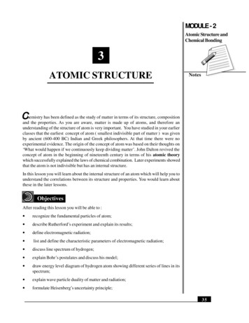
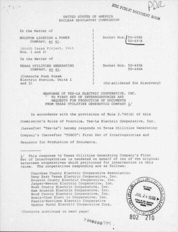
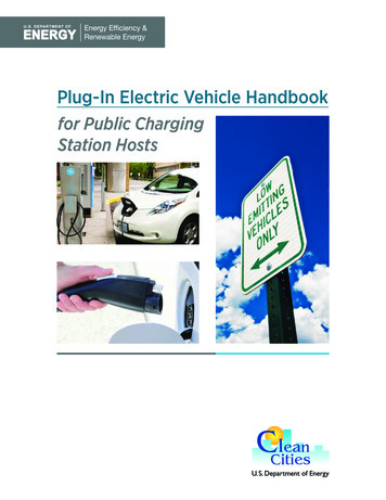
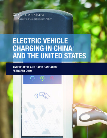
Electric Train ExperimentPurposeTo build an “electric train,” utilizing uninsulated copper wire, a battery, and powerfulmagnets. The result is a fascinating and cheap experiment that displays the basic principles ofelectromagnetism and engineering. This experiment is guided towards STEM education andoutreach, particularly for under funded schools. The end product is a train made of a batteryand magnets that propels itself through a coil of wire using electromagnetic force. Figure 1depicts the final product.Figure 1: Finished Solenoid Track and Battery TrainPrinciples Of OperationWe will put two basic principles of electromagnetics and magnetism to work to create anelectric train. The first is the magnetic field created by a solenoid. A solenoid is simply a coil ofwire wrapped in a tightly packed helix shape as shown by the white lines in Figure 2.Figure 2: Solenoid and its Magnetic Field(Source: c/solenoid.html)When the solenoid is connected to a voltage source, a current (I) is provided along the wire.The current, which is going through this circularly looped wire, results in a constant, (ideally)uniform magnetic field (B) through the center of the coil of wire. The resultant magnetic field
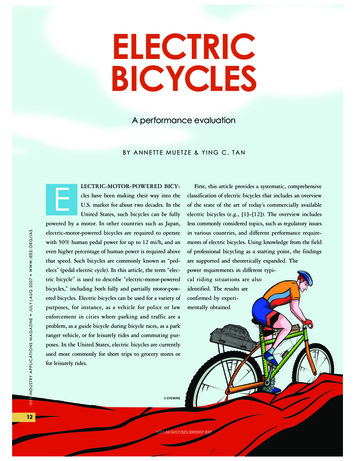
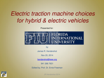
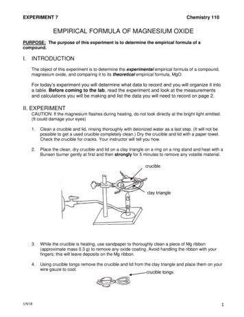
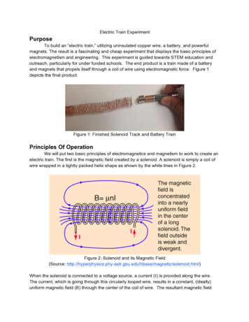
lines are shown by the blue lines in Figure 2. Thus, an electromagnet is created. The strength ofthe magnetic field (B µnI) is proportional to both the number of turns of wire per unit length(n N/L) and the strength of the current passing through.Ampere’s Right Hand Rule, shown in Figure 3, illustrates that a current carrying wiregenerates a magnetic field around the wire. Point the thumb of your right hand in the directionof current along a wire then curl your fingers inward. The direction of your curled fingers givesthe direction of the magnetic field (red lines in Figure 3). The magnetic field radiates outward ina circle, with the magnetic field strength decreasing as you go farther from the current carryingwire. This information can be used to confirm the magnetic field lines for a solenoid depicted inFigure 2. Simply, follow along the curve of the solenoid with your thumb and confirm that thedirection of the magnetic field will always be through the center of the solenoid.Figure 3: Ampere’s Right Hand Rule(Source: http://en.wikipedia.org/wiki/Right-hand rule)The second principle utilized is the premise of magnetic poles. A magnet always has anorth and south pole. Figure 4 shows that if you break a magnet in half, the two halves willcreate new poles such that each magnet still has a North and South pole.
Figure 4: Magnetic DipolesThe opposite North and South poles attract to each other and same poles (N-N and S-S) repel.A magnetic field can also interact with magnets and cause a force upon the magnet inside themagnetic field.How do these two principals connect to create an electric train? The key is that themagnets are Neodymium. Neodymium magnets are man made magnets made up of acombination of iron, boron, and neodymium (these are all located on the periodic table ofelements). These three materials are melted, combined, and then passed through a very strongelectromagnetic field to magnetise them¹. This combination of conducting materials allowsNeodymium magnets to conduct electricity. Most other magnets, such as ceramic magnets, arenon-conducting. Ceramic magnets are also man made, made up of a combination of powderslike iron oxide and strontium carbonite². Based on the materials that make them up, ceramicmagnets do not conduct electricity. Thus, when the neodymium magnets are attached to eitherend of the battery and resting on the uninsulated copper wire, a local circuit is made along thelength of the battery. The circuit is made from the positive terminal of the battery, into themagnets, through the copper wire of the solenoid and back into the magnets on the negativeterminal of the battery. This local circuit provides the current to create the magnetic field withinthe solenoid. Next, the geometry of the battery is such that the magnets are on either end of thebattery. This causes the magnetic poles of the magnets attached to the battery tosimultaneously be pushed in and out of the local circuit (depending on which magnet you’relooking at). This force causes the battery train to move. However, as the train moves it creates anew localized circuit that perpetuates the motion. Note: The magnets must be oriented such thatthe same pole is facing each other. This allows the forces to be in the same direction and tocombine; otherwise, the forces will cancel out and the train will not move. If both magnets flip tohave the other dipole facing out, the force will reverse direction as shown in figure 5.
Figure 5: Depiction of Physics of Electric Train(Source: Dan Zimmerman, e-worldssimplest-electric-toy-train)Parts ListPer group performing experiment: 4 or 6 Neodymium Magnets 1/2 x 1/8 inch Disc N48 6 yard spool of 20 gauge, uninsulated copper wire (5.5m, d .032in .812mm) This must be 1 AAA battery 1 dowel rod (or other long cylinder) of ¾ inch diameterNon-essential items (For an improved experience) Scotch Tape Wire Cutters Small PliersExperimental ProcedureBefore beginning, if you are interested in combining multiple solenoid “tracks” together,make sure to pay attention to Note 1 in the Advanced Procedure section when you start coilingthe copper wire. You may wish to combine multiple “tracks” together to get the most out of theexperiment, as this permits you to create a longer track, to experiment with how powerful the
train propulsion is, and how well the train will follow the track if you add in curves. Follow Note 2in the Advanced Procedure section when you have completed the Experimental Proceduresection and are ready to combine multiple solenoid “tracks.”Creating the track is much easier if done with two people. To start creating a solenoid“track,” one person (person A) should take a strand of copper wire approximately 6 yards inlength and another person (person B) should grab a single 6” dowel rod. While person B holdsthe rod, person A should uncoil 3-4 inches of copper wire from the 6 yard spool. Person Ashould then curl that amount of the wire over the top of the rod and then under and backtowards himself. Then pull that tight and hold that part of the wire with your finger. Then curl therest of the wire. Note: it is easiest to roll the dowel rod to curl the wire rather than trying tophysically curl the wire around the rod. Be EXTREMELY careful to make a very tight, smoothloop around the rod with very little spaces in between the curls, and do not overlap the wire. Ifthe solenoid doesn’t have smooth and well-rounded turns, the train won’t work as well.Figure 6a: Solenoid Curling (note photograph show insulated wire, but you should be using barecopper wire)
Figure 6b: Solenoid CurlingFigure 6c: Solenoid CurlingThe wire cutters and small pliers are very handy here if you mess up and want to uncoila section of wire or simply cut it off and try again for a smoother curve. Continue wrapping the
coil until you finish the spool of wire. This should create, roughly, a 6 inch long solenoid “track.”Carefully push the dowel rod out from within the coil by firmly holding the solenoid and pushingthe dowel rod out with your finger. Be careful not to crush the solenoid. Once the solenoid isfree of the dowel rod, put the solenoid aside.Figure 7: Finished SolenoidNext, take a stack of 2 or 3 magnets (half of what you have), and attach them togetheron one end of the battery (it does not matter which side you choose). Take the other stack of 2or 3 magnets and carefully find the side that repels from the outward face of the magnet stackalready attached to the battery. Attach the stack of magnets in your hand to the opposite side ofthe battery, with the repelling side facing out. This is in order to check the direction of therelative magnetic polarity between this stack and the stack already on the battery. For this towork, you must make sure that the same polarity is facing outwards (so either both N faces ofthe magnets face away from the battery or both S faces face out).Put your newly created electric train inside the solenoid “track” and watch it go. If thebattery repels out of the track instead of going through, simply turn the train around. If the traindoes not move at all, the orientation of the magnets may be incorrect. In this case, take off onestack of magnets, flip them around, reattach to the battery, and try again.Advanced ProcedureThe notes in this section guide you when trying to combine multiple solenoid “tracks” intoone larger track.Note 1: Be careful which way you are looping the coil around the dowel (over and under thedowel rod from left to right vs. under and over the dowel rod from left to right). This will onlyhave an effect when separate solenoid “tracks” are combined. If two solenoid “tracks” arelooped around in opposite directions they will generate magnetic fields in opposite directions.So, if the train goes one way through one of the “tracks,” as soon as it enters the other track itwill be repelled the opposite way.
Note 2: To combine two solenoid tracks that are wrapped the same way, it is best to insert adowel rod into the end of one track and the beginning of the other in order to overlap the ends ofeach “track.” Then, tape the ends together to ensure the battery moves cleanly through bothtracks. Be careful not to deform the circular area of the solenoid too much, or the train might notbe able to pass through.
Sources:http://hyperphysics.phy- .org/wiki/Right- ‐hand rulehttp://thekidshouldseethis.com/post/how- ‐to- ‐make- ‐the- ‐worlds- ‐simplest- ‐electric- ‐toy- /wiki/Electromagnet
Ampere's Right Hand Rule, shown in Figure 3, illustrates that a current carrying wire generates a magnetic field around the wire. Point the thumb of your right hand in the direction of current along a wire then curl your fingers inward. The direction of your curled fingers gives the direction of the magnetic field (red lines in Figure 3).