Transcription
ANALYSIS AND OPTIMIZATION MACHINING PARAMETER BASE ONDIFFERENT TYPE OF MATERIAL IN INCREMENTAL FORMING PROCESS(ALGOR SIMULATION)MOHD HISHAM BIN SIDI AHMADThesis submitted in fulfilment of the requirementsfor the award of the degree ofBachelor of Mechanical EngineeringFaculty of Mechanical EngineeringUNIVERSITI MALAYSIA PAHANGNOVEMBER 2009
iiSUPERVISOR’S DECLARATIONI hereby declare that I have checked this project and in my opinion, this project isadequate in terms of scope and quality for the award of the degree of Bachelor ofMechanical Engineering with Manufacturing Engineering.SignatureName of Supervisor: MR. ROSDI BIN DAUDPosition: SUPERVISORDate:NOVEMBER 2009
iiiSTUDENT’S DECLARATIONI hereby declare that the work in this project is my own except for quotations andsummaries which have been duly acknowledged. The project has not been accepted forany degree and is not concurrently submitted for award of other degree.SignatureName: MOHD HISHAM BIN SIDI AHMADID Number: ME07068Date:NOVEMBER 2009
ivCOPYRIGHT
vDedicated to my beloved father and mother
viACKNOWLEDGEMENTSI would like to express my gratitude and appreciation to all those who gave methe possibility to complete this report. I would also like to acknowledge with muchappreciation the crucial role of the staff in Mechanical Laboratory, who gave me apermission to use all the necessary tools in the laboratory. In preparing my projectresearch and this project report, I was to contact with many people such as researcher,academicians, engineers, practitioners and fellow friend.Special thanks are due to my supervisor En. Rosdi Bin Daud , co-supervisor Dr.Ahmad Syahrizan Bin Sulaiman and Mr. .Fadhlur Rahman Bin Mohd Romlay whosehelp, stimulating suggestions, germinal ideas, invaluable guidance, continuousencouragement and constant support in making this research possible.
viiABSTRACTThis research was carried out to develop and analysis of an incremental formingmachine controlled by personal computer numerical control (PCNC) and ALGORsoftware for simulation. Incremental Sheet Forming (ISF) is one kind of sheet metalforming. It is based on using of simple spherical tool, which is moved along personalcomputer (PC) controlled tool path. Aim of this study is analysis in stepdown for newdevelopment of incremental forming. The paper presents the analyses about theimplication and justification for forming process. Using FE analysis have been achievedwith the purpose to compare between experimental and simulation. The process andanalysis have been use to determine the stepdown in the design phase for continuousoperation. Additionally, this paper also shows investigate the effect different type ofmaterial on yield stress and Springback and investigate the deformation mechanicsunder an optimization with different type of material.Keywords: Incremental Forming; ALGOR; Yield Stress; Springback; ProcessParameters; PCNC
viiiABSTRAKPenyelidikan ini telah dijalankan bagi membangunkan dan analisis satu tokokanmembentuk mesin diawasi oleh kawalan komputer peribadi dan perisian ALGOR untuksimulasi. Kepingan Tokokan Membentuk (ISF) adakah satu jenis mesin untukmembentuk kepingan logam. Ini adalah berasaskan pada penggunaan mata alat spherayang mudah, yang mana digerakan oleh mesin yang dikawal oleh komputer (PC).Matlamat kajian ini ialah analisis dalam langkah turun untuk pembangunan barutokokan membentuk. Kertas ini menunjukan analisis tentang implikasi dan justifikasiuntuk proses membentuk. Menggunakan analisis elemen terhad (FE) telah dicapaidengan tujuan untuk membandingkan antara ekperimen dan simulasi. Proses dananalisis digunakan untuk bagi menentukan langkah turun dalam fasa reka bentuk untukoperasi berterusan. Tambahan pula, kertas ini juga menunjukkan menyiasat kesanmengunakan bahan berbeza pada tegasan alah dan kebolehan logam kembali kebentukasal dan menyiasat kecacatan mekanik-mekanik dibawah satu pengoptimuman denganjenis bahan yang berbeza.
ixTABLE OF CONTENTSPageSUPERVISOR’S DECLARATIONiiSTUDENT’S TviiABSTRAKviiiTABLE OF CONTENTSixLIST OF TABLESxiiLIST OF FIGURESxiiiLIST OF ABBREVIATIONSxvNOMENCLATURExviCHAPTER 1INTRODUCTION1.1Introduction11.2Objective of the study21.3Scope21.4Problem statement3CHAPTER 2LITERATURE REVIEW2.1Introduction42.2Characteristics Of Formability In The Incremental Forming52.3Types Of Incremental Forming72.4Forming Tool Spindle Speeds92.5Springback142.6Limits Diagrams162.72.6.1 The Stress Strain CurveFe Analysis (ALGOR Software)1617
xCHAPTER 3METHODOLOGY3.1Introduction203.2Project Flow Diagram203.3Plan The Experiment233.4Research Procedure233.5Conducting The Experiment And Simulation253.5.1Design product in ArtCAM Pro253.5.2Setting Process Parameter253.5.3Design Sample of Incremental Forming Products Analysisin ALGOR software263.5.4FE Analysis29CHAPTER 4RESULTS AND DISCUSSION4.1Introduction354.2Development Of Fe Model For ISF4.2.1 Model Information36364.3Data Collection And Graph414.3.1414.4Result simulation ALGORDiscussionCHAPTER 549CONCLUSION AND RECOMMENDATIONS5.1Conclusions515.2Recommendations For Future Research52REFERENCES53
xiAPPENDICESA1Gantt chart for PSM 156A2Gantt chart for PSM 257B1Aluminum Properties58B2Zinc Properties59B3General Properties of Steels60
xiiLIST OF TABLESTable No.TitlePage3.1Aluminium Alloy 5052-O273.2Zinc273.3Steel (ASTM - A572)283.4Stainless Steel (AISI 309)283.5Titanium Ti-6Al-4V (Grade 5), Annealed294.1Part Information364.2Instruction for simulation374.3Comparison Theory vs ALGOR (z 0.5 mm)424.4Comparison Theory vs ALGOR (z 1.0 mm)444.5Comparison Theory vs ALGOR (z 1.5 mm)464.6Comparison and Assumption Data for Experimental47
xiiiLIST OF FIGURESFigure No.TitlePage2.1Incremental forming of sheet metal on Incremental formingmachine52.2Comparison of FLCs in both incremental and conventionalforming methods62.3Schematic diagram of incremental forming72.4(a) SPIF, (b) TPIF with partial die and (c) TPIF with full die(Shankar et al., 2005).92.5Tool geometry and spindle speeds.102.6A universal tool head (Allwood et al., 2005)112.7Single Point Incremental Forming of a cone122.8FLDo for different step sizes for AA 1050-0, with upper and lowerbounds, with a 12 mm diameter tool (Micari, 2004).132.9FLD for to 1.5 mm DC04; influence of forming tool size uponforming limits (Hirt et al., 2002). Graph points x1 to x4correspond to positions on the sheet marked by x.132.10Forming of a cone, showing the forming tool inside the cone andthe outside surface of the cone. The steps shown are in sequentialorder and are for incremental, unidirectional steps (Jeswiet andRecent, 2004).142.11Illustration of local springback in ISF (Bambach, 2008; Bambachet al., 2009)163.1Project Flow Chart for FYP 1213.2Overall Project Flow Chart223.3Experimental Procedure243.4Example process Parameter for tool size 6 mm263.5Design of sheet metals for incremental forming test303.6Load Curve Information31
xiv4.1Finite elements modeling of ISF364.2Simulation result for Aluminum and Stainless Steel384.3Simulation result for Steel and Titanium384.4Simulation result for Zinc394.5Simulation Yield Stress result for Aluminum and Stainless Steel394.6Simulation Yield Stress result for Steel, Titanium and Zinc40
xvLIST OF ABBREVIATIONSAISIAmerican Iron & Steel InstituteASTMAmerican Society for Testing and MaterialsCAMComputer Aided ManufacturingCNCComputer Numerical ControlFEFinite ElementFEMFinite Element ModelFLCForming Limit CurveFLDForming Limit DiagramISFIncremental Sheet FormingIFIncremental FormingMESMechanical Event SimulationSMISmall and Medium IndustrySMESmall and Medium EnterpriseSPIFSingle Point Incremental FormingTPIFTwo Point Incremental FormingUTSUltimate Tensile StressYYield Stress
xviNOMENCLATUREAAreaEModulus NNewtontThicknessMPaMega Pascal
CHAPTER 1INTRODUCTION1.1INTRODUCTIONIncremental Sheet Forming (ISF) was first explored at the Institute forManufacturing in 1990 by Colin Andrew, and then taken up in Japan during the 1990s(Allwood et al., 2005). Allwood also said that, many researcher or studies in ISF to datehave been with one indenter only, and based around modified Computer NumericalControl (CNC) milling machines. A new incremental forming machine wascommissioned in October 2004 at the Department’s Institute for Manufacturing, whichis the first dedicated rig to be built outside Japan (Allwood et al., 2005).Nowadays, have a many new incremental forming machine were develop by thecompany, university and other institution. Researchers of Faculty of MechanicalEngineering (FKM) from Universiti Malaysia Pahang (UMP) also develop newincremental forming machine controlled by personal computer – numerical control (PCNC) in March 2008. The incremental forming process which runs without mould can beused to replace stamping applications which is very costly due to the mould application.The application of the machine is for low batch sheet metal manufacturing product. Thisresearch will produce a new concept of forming process which is cheaper, efficient andsuitable for SMI/SME industry, which will benefit the manufacturing industry in ourcountry.As a part of graduation requirements, the final year degree students of Faculty ofMechanical Engineering from Universiti Malaysia Pahang (UMP) will have to submitthe thesis as a final year project for duration of two semesters. These projects propose to
2analysis and optimization machining parameter base on different type of material inincremental forming machine using ALGOR software (simulation).1.2OBJECTIVE OF THE STUDYThe objective that must be carried out by this study in order to get the analysis andoptimization machining parameter of Incremental Forming (IF):1.2.1To study and understanding the concept and principle ofIncremental Forming (IF).1.2.2To investigate the deformation mechanics under an optimizationwith different type of material.(stepdown)1.2.3To investigate the effect different type of material on Springbackin ALGOR Simulation.1.3SCOPE1.3.1Predictable model will be developed using ALGOR software1.3.2This project need to operate the ALGOR software with five ofmaterial and different Nodal Prescribed Displacement Z (-ve) 0.5 mm, 1.0 mm and 1.5 mm. [Aluminum Alloy 5052O,Titanium Ti-6Al-4V , Steel (ASTM - A572), Zinc andStainless Steel (AISI 309)]1.3.3This project needs use same thickness of material is 0.5 mm.1.3.4During the analysis, data must be recorded and the analysis needsto be done on it.1.3.5By analyze and comparison of data, suitable parameter can beselected.
31.4 PROBLEM STATEMENT1.4.1Springback is a very important factor to influence the quality ofsheet metal forming. Springback are main goal that need to bearchive in order to get high accuracy, high productivity and costeffective product in incremental sheet forming (ISF) process.However, as what world cannot deny that, practical is not asperfect as theory which due to large number of variable and theuncertain nature of the process, even highly skilled operator Springback of the workpiece is one of the main problems toachieve since this characteristic is close relation with accuracy.1.4.2ISF not have guideline to form sheet metal especially settingstepdown parameter for different type of material.
4CHAPTER 2LITERATURE REVIEW2.1 INTRODUCTIONIncremental Sheet Forming (ISF) is an alternative to metal stamping or pressing.Pressing requires specialist tooling for each product, which is expensive and difficult todesign because pressing requires large batch volumes to offset tooling costs. ISF is avery promising technology to manufacture sheet metal products by the ComputerNumerical Control (CNC) controlled movement of a simple forming tool. Incrementalforming is one of the technologies that have emerged as an alternative to conventionalsheet metal forming processes for mass customization. Conventionally a sheet-metalcomponent is manufactured by using dies and punches that depend on the dimensions ofthe component. This conventional method is adequate for mass production because thecost of dies and punches can be shared with a large number of products. However, whena short series production is required, the conventional methods based on dies, likestamping or drawing are not usable anymore. Therefore, new production methods haveto be developed in order to fulfill the requirements imposed by the low seriesproduction industries.Due to the recent diversification of the customer’s demand in this field, newmanufacturing methods for a small-size production need to be developed. Among thevarious methods developed over the past few years (Iseki and Kumon, 1994; Mori et al,1996; Otsu et al, 2000) the ISF which utilizes a simple tool has been studied with agreat attention (Matsubara, 1994; Kim and Yang, 2000). ISF is commonly regarded as a
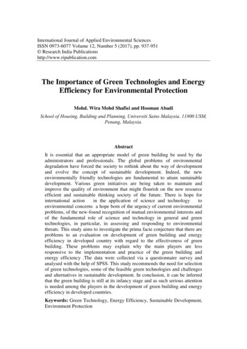
5die-less forming process which can form complex three-dimensional parts usingrelatively simple tools. It has received increasing attention from the engineeringcommunity due to its flexibility and low cost. This unique combination enables therapid prototyping of functional sheet metal parts before mass production. In addition, itoffers a valid manufacturing process to match the need of mass customization.Incremental forming has found numerous applications in automobile, aerospaceindustries, in biomedical applications, such as customized ankle support and bespokearchitectural features.2.2 CHARACTERISTICS OF FORMABILITY IN THE INCREMENTALFORMINGIn the incremental forming (IF) of sheet metal, a simple-shaped tool imposesdeformation locally on the sheet in a consecutive manner. An example of theincremental forming, called the negative forming, is shown in Fig. 2.1. In this example,the ball tool moves on the sheet according to a programmed tool path on an IncrementalForming machine. The sheet is located with the periphery fixed by bolts on a die, whichis hollow and square in cross section.Figure 2.1: Incremental forming of sheet metal on Incremental forming machine.
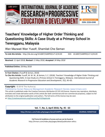
6The tool moves horizontally as well as vertically by a tool-path program, andforms a shape from the sheet. While the tool moves straight on a horizontal plane, thedeformation that occurs at the starting and ending points of the straight line is biaxialstretching. The deformation that occurs between these points is plane-strain stretching.Shown in Fig. 2.2, the forming limit curve (FLC) appears to be a straight line with anegative slope in the positive region of the minor strain and thus the formability can beexpressed as the value of εmax εmin (Iseki, 2001). It is noted that the formability isgreatly enhanced in the case of plane-strain stretching. Therefore, a greater deformationof a sheet metal can be achieved in the incremental forming. The other characteristic isthe formability of the deformation increases as the size of the tool or the magnitude ofthe vertical feed decreases.Figure 2.2: Comparison of FLCs in both incremental and conventional formingmethods.In Fig. 2.3 shown the concept of incremental forming by tool is presentedschematically. The path of the ball is often a closed or near-closed loop on horizontalplane and the forming depth is controlled by tool depth.
7Figure 2.3: Schematic diagram of incremental forming2.3 TYPES OF INCREMENTAL FORMINGThe great interest in this new technique is due to the fact that it allows obtainingcomplex shapes, only using a simple tool, mounted on dedicated equipment (Lamminenet al, 2003; Shankar et al, 2005) or also on a general purpose 3-Axis CNC machine,which follows a path generated by CAM software. Incremental forming processes canbe divided essentially in two families, depending on the number of contact pointsbetween sheet, tool and die (when present).Therefore, it is possible to distinguishbetween single point incremental forming (SPIF), and two point incremental forming(TPIF):2.3.1SPIF (Fig. 2.4a) has been investigated by many researchers, who underlinedits great flexibility, due to the absence of specific dies. Many studies (Kimand Yang, 2000; Shim and Park, 2001; Jeswiet et al., 2005) report theincreased drawing ratio obtainable with this method in comparison withconventional deep drawing processes. SPIF is indicated, and has beenstudied, above all for the realization of simple, nearly symmetric shapes (Daiet al., 2000; Pohlak et al., 2004a,b; Iseki, 2001; Kim and Park, 2002; Parkand Kim, 2003), with few exceptions (Ambrogio et al., 2005; Tanaka et al.,
82005). The limit of this technique is the low geometric accuracy, which oftenmakes the realized objects far from the requested tolerances. Many studies(Hirt et al., 2004, 2003b) have been performed in order to overcome thisproblem some proposed solutions are, for instance, multistage SIF (Kim andYang, 2000; Iseki and Naganawa, 2002; Micari and Ambrogio, 2004) or theuse of an algorithm (Hirt et al., 2003b) for the tool path correction. Thesesolutions lead to a better dimensional accuracy, but they require longerproduction time.2.3.2TPIF is based on the presence of a partial (Fig. 2.4b) or full die (Fig. 2.4c),which supports the sheet during the deformation. When using TPIF (Jeswietet al., 2005), the sheet is contemporarily deformed in two points: the contactpoints between tool and sheet and between sheet and die. This method ofsheet defect could cause sheet reduction formability in comparison withSPIF, but it allows increased reachable geometric accuracy within one singlepass. Use one TPIF process's detail called asymmetric incremental sheetforming (AISF), it was getting acquire a good for complex dimensionaccuracy, not axis of symmetry geometries, characterized by depression andconvex surfaces. This, together with improve dimensional accuracy able, isgreat advantage of TPIF in comparison with SPIF, and it makes TPIF moreattractive of SPIF for application inside industrial realize complex formprototype.
3.5.1 Design product in ArtCAM Pro 25 3.5.2 Setting Process Parameter 25 3.5.3 Design Sample of Incremental Forming Products Analysis in ALGOR software 26 3.5.4 FE Analysis 29 . 1.3.2 This project need to operate the ALGOR software with five of material and different Nodal Prescribed Displacement Z (-ve) 0.5 mm, 1.0 mm and 1.5 mm. [Aluminum .