Transcription
13 SEERP5RD SERIESUSER’S MANUAL & INSTALLATION INSTRUCTIONSSingle Package Air Conditioner - Single Stage, R-410AIMPORTANTPlease read this information thoroughly and become familiar with the capabilities and use ofyour appliance before attempting to operate or maintain this unit. Keep this literature whereyou have easy access to it in the future. If a problem occurs, check the instructions and followrecommendations given. If these suggestions don’t eliminate your problem, call your servicingcontractor.The Installation Instructions are primarily intended to assist qualified individuals experiencedin the proper installation of this appliance. Some local codes require licensed installation/service personnel for this type of equipment. Please read all instructions carefully beforestarting the installation.DO NOT DESTROY. PLEASE READ CAREFULLY ANDKEEP IN A SAFE PLACE FOR FUTURE REFERENCE.
USER INFORMATIONImportant Safety Information .3WARRANTY INFORMATIONOperating Instructions .3Cooling Operation .3Heating Operation .3Turning the Air Conditioner Off .3Operating the Indoor Blower Continuously .3A warranty certificate with full details is included with theAir Conditioner. Carefully review these responsibilities withyour dealer or service company. The manufacturer will notbe responsible for any costs found necessary to correctproblems due to improper setup, improper installation,adjustments, improper operating procedure on the partof the user, etc. Some specific examples of service callswhich are not included in the limited warranty are: Correcting wiring problems in the electrical circuitsupplying the Air Conditioner. Resetting circuit breakers or other switches. Adjusting or calibrating of thermostat.Air Conditioner Maintenance.3Troubleshooting.3INSTALLER INFORMATIONImportant Safety Information .4General Information .5Before You Install this Unit .5Locating the Air Conditioner .5Minimum Clearance Requirements .5Service Access Clearances .5Clearances to Combustible Materials .5Air Duct System .5Air Conditioner Installation .6Unpacking the Unit .6Installing Return & Supply Collars.6Supply Duct .6Return Duct .7Locating & Installing the Return Air Assembly .7Connecting the Return & Supply Air FlexibleDucts .7Locating & Installing the Supply Dampers.7Condensate Drainage .8Electrical Connections .8Pre - Electrical Checklist .8Line Voltage .8Overcurrent Protection .9Grounding.9Thermostat / Low Voltage Connections .9Cooling Thermostat .9Heat/Cool Thermostat .9Blower Speed .10Standard PSC Motor .10High Efficiency ECM Motor .102Startup & Adjustments .10Pre - Start Checklist .10Start - Up Procedure .10System Cooling .10Emergency Heat .11Adjustment of Refrigerant Charge .11Charging an R410A Unit in AC Mode with OutdoorTemperatures above 55 F .12Air Conditioner Maintenance.12Component Functions .12High Pressure Switch .12Low Pressure Switch .12Replacement Parts .12Figures & Tables .13Figure 10 - Phys. Data & Unit Dimensions .13Wiring Diagrams .14Figure 11 - P5RD - w/ ECM Motor .14Figure 12 - P5RD - w/ PSC Motor .15Refrigerant Charging Tables .16Table 4 - P5RD-024K (2 Ton Units) .16Table 5 - P5RD-030K (2.5 Ton Units) .16Table 6 - P5RD-036K (3 Ton Units) .17Table 7 - P5RD-042K (3.5 Ton w/ X-13 Motor) .17Table 8 - P5RD-042KA (3.5 Ton w/ PSC Motor).18Table 9 - P5RD-048K (4 Ton Units) .18Figure 13 - P5RD-048KA (4 Ton w/ TXV Valve) .19Table 10 - P5RD-060K 5 Ton Units .19Installation / Performance Checklist .20
USER INFORMATIONIMPORTANT SAFETY INFORMATIONSafety markings are used to designate a degree or levelof seriousness and should not be ignored. WARNINGindicates a potentially hazardous situation that if notavoided, could result in personal injury or death. CAUTIONindicates a potentially hazardous situation that if notavoided, may result in minor or moderate injury or propertydamage.OPERATING INSTRUCTIONSNOTE: Thermostat styles vary. Some models may notinclude the AUTO mode and others will have the AUTOin place of the HEAT and COOL. Others may include allthree. Please refer to the thermostat manufacturer’s Usermanual for detailed programming instructions.Cooling Operation1. Set the thermostat’s system mode to COOL or AUTOand change the fan mode to AUTO. See Figure 1.2. Set the temperature selector to the desired temperaturelevel.The outdoor fan, compressor, and blower motor willall cycle on and off to maintain the indoor temperatureat the desired cooling level.Heating Operation(if optional heater kit is installed)1. Set the thermostat’s system mode to HEAT or AUTOand change the fan mode to AUTO. See Figure 1.2. Set the temperature selector to the desired temperaturelevel. The outdoor fan, blower motor, and heater kit willcycle on and off to maintain the indoor temperature atthe desired heating level.Turning the Air Conditioner OFFChange the thermostat’s system mode to OFF and the fanmode to AUTO (See Figure 1). NOTE: The system will notoperate, regardless of the temperature selector setting.Operating the Indoor Blower ContinuouslyThe continuous indoor blower operation is typically used tocirculate the indoor air to equalize a temperature unbalancedue to a sun load, cooking, or fireplace operation.Set the thermostat fan mode to ON (Figure 1). The indoorblower starts immediately, and will run continually untilthe fan mode is reset to AUTO.The continuous indoor blower operation can be obtainedwith the thermostat system mode set in any position,including OFF.AIR CONDITIONER MAINTENANCEProper maintenance is most important to achieve the bestperformance from the appliance and should be performedfrequently at the beginning of each air conditioning season.WARNING:Your Air Conditioner contains liquid andgaseous refrigerant under pressure. Installationand servicing should only be attempted byqualified, trained personnel thoroughly familiarwith the equipment and safe responsiblerefrigerant handling procedures. Failure tocomply with this warning could result inequipment damage, personal injury, or death. Keep the unit clean. Hose off periodically and keepunit fins clear of leaves and grass clippings. Keep the unit clear of obstructions. DO NOT obstructairflow with tall plants or shrubs. DO NOT store gasolineor other flammable materials on or near the unit. Never operate the appliance without a filter installed inthe return air duct. Inspect filters frequently and replacewhen necessary with filter of same dimensional size.TROUBLESHOOTINGIf the unit fails to operate, check the following: Check the thermostat setting. Make sure the systemmode and temperature settings are correct. Check the electrical panel for tripped circuit breakers. Check the filters for dust accumulation. Check the unit and make sure it is clean and not coveredwith grass or leaves. If the items above don’t resolve your problems, thencall your nearest service ure 1. Digital Thermostat3
INSTALLER INFORMATIONIMPORTANT SAFETY INFORMATIONPlease read all instructions before servicing this equipment.Pay attention to all safety warnings and any other specialnotes highlighted in the manual. Safety markings areused frequently throughout this manual to designate adegree or level of seriousness and should not be ignored.WARNING indicates a potentially hazardous situation thatif not avoided, could result in personal injury or death.CAUTION indicates a potentially hazardous situation thatif not avoided, may result in minor or moderate injury orproperty damage.WARNING:Shut off all electrical power to the unit beforeperforming any maintenance or service on thesystem. Failure to comply may result in personalinjury or death.WARNING:Unless noted otherwise in these instructions,only factory authorized parts or accessorykits may be used with this product. Improperinstallation, service, adjustment, or maintenancemay cause explosion, fire, electrical shock orother hazardous conditions which may resultin personal injury or property damage.WARNING:P5RD units are fully charged with R-410Arefrigerant and ready for installation. Whena system is installed according to theseinstructions, no refrigerant charging is required.If repairs make it necessary for evacuationand charging, it should only be attemptedby qualified, trained personnel thoroughlyfamiliar with this equipment. Some local codesrequire licensed installation service personnelto service this type of equipment. Under nocircumstances should the equipment ownerattempt to install and/or service this equipment.Failure to comply with this warning could resultin equipment damage, personal injury, or death.4CAUTION:This unit uses refrigerant R-410A. DO NOT useany other refrigerant in this unit. Use of anotherrefrigerant will damage the unit.WARNING:The information listed below must be followedduring the installation, service, and operationof this unit. Unqualified individuals shouldnot attempt to interpret these instructions orinstall this equipment. Failure to follow safetyrecommendations could result in possibledamage to the equipment, serious personalinjury or death. The installer must comply with all local codes andregulations which govern the installation of this typeof equipment. Local codes and regulations takeprecedence over any recommendations contained inthese instructions. Consult local building codes andthe National Electrical Code (ANSI CI) for specialinstallation requirements. All electrical wiring must be completed in accordancewith local, state and national codes and regulationsand with the National Electric Code (ANSI/NFPA 70)or in Canada the Canadian Electric Code Part 1 CSAC.22.1. This equipment contains liquid and gaseous refrigerantunder high pressure. DO NOT USE ANY PORTION OFTHE CHARGE FOR PURGING OR LEAK TESTING.Installation or servicing should only be performed byqualified trained personnel thoroughly familiar with thistype equipment. This unit is designed for outdoor installations only andshould be located in a position as shown on page 5. Follow all precautions in the literature, on tags, andon labels provided with the equipment. Read andthoroughly understand the instructions provided withthe equipment prior to performing the installation andoperational checkout of the equipment.
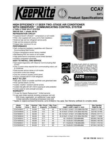
The P5RD packaged air conditioner is designed onlyfor outdoor ground level installations and can be readilyconnected to the high static duct system of a home.This unithas been tested for capacity and efficiency in accordancewith A.R.I. Standards and will provide many years of safeand dependable comfort, providing it is properly installedand maintained. Abuse, improper use, and/or impropermaintenance can shorten the life of the appliance andcreate unsafe hazards.To achieve optimum performance and minimize equipmentfailure, it is recommended that periodic maintenance beperformed on this unit. The ability to properly performmaintenance on this equipment requires certainmechanical skills and tools.Before You Install this Unit The cooling load of the area to be conditioned must becalculated and a system of the proper capacity selected.It is recommended that the area to be conditioned becompletely insulated and vapor sealed. Check the electrical supply and verify the power supplyis adequate for unit operation. If there is any questionconcerning the power supply, contact the local powercompany. All units are securely packed at the time of shipment andupon arrival should be carefully inspected for damageprior to installing the equipment at the job site. Verifycoil fins are straight. If necessary, comb fins to removeflattened or bent fins. Claims for damage (apparent orconcealed) should be filed immediately with the carrier. Please consult your dealer for maintenance informationand availability of maintenance contracts. Please readall instructions before installing the unit.Locating the Air Conditioner Survey the job site to determine the best location formounting the outdoor unit. Select a solid, level position,preferably on a concrete slab, slightly above the gradelevel, and parallel to the home. If possible, select a sitefor the unit that is as close as possible to the proposedreturn grille location. DO NOT PLACE UNIT UNDERTHE HOME. The unit should be located with consideration ofminimizing the length of the supply and return ducts.If practical, place the air conditioner and its ducts inan area where they will be shaded from the afternoonsun, when the heat load is greatest. The length of the supply and return ducts should bekept to a minimum with no sharp radius bends. Overhead obstructions, poorly ventilated areas, andareas subject to accumulation of debris should beavoided. The hot condenser air must be dischargedup and away from the home, and if possible, in adirection with the prevailing wind. Do not place the unitin a confined space. See Figure 10 (page 13) for unitdimensions. Sufficient clearance for unobstructed airflow throughthe outdoor coil must be maintained in order to achieverated performance. Consideration should also be given to availability ofelectric power, service access, noise, and shade.Minimum Clearance RequirementsSufficient clearance for unobstructed airflow through theoutdoor coil must be maintained in order to provide roomfor proper servicing and achieve rated performance. SeeFigure 2 for minimum clearances to obstructions.Service Access ClearancesBlower access panel side .24”Electrical compartment access panel side .12”Clearance between overhang & top of unit.72”Clearance around condenser coil area to wall orshrubs (excludes duct panel side) .12”Clearances to Combustible MaterialsSupply and return air ducts .0”Duct connection side .0”12"24"TOP OF UNITTO BEUNOBSTRUCTEDGENERAL INFORMATION12"0"Figure 2. Minimum Unit ClearancesAir Duct SystemAir ducts must be installed in accordance with the standardsof the National Fire Protection Association “Standard forInstallation of Air Conditioning and Ventilation Systems”(NFPA 90A), “Standard for Installation of Residence TypeWarm Air Heating and Air Conditioning Systems” (NFPA90B), these instructions, and all applicable codes. NFPApublications are available by writing to: National FireProtection Association, Batterymarch Park, Quincy, ME02269 or visit www.NFPA.org on the web. Design the duct work according to methods describedby the Air Conditioning Contractors of America (ACCA). The supply duct system, including the number andtype of registers, will have much more effect on theperformance of the system than any other factor. Theduct must be sufficiently large to conduct an adequateamount of air to each register. See Figure 3 (page 6).5
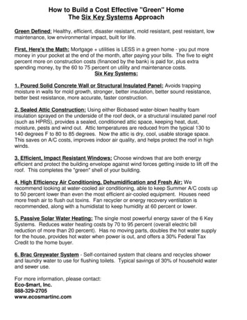
SINGLE DUCT APPLICATIONMULTIPLE DUCT APPLICATIONFigure 3. Single & Multiple Duct Applications Duct work should be attached directly to the unit flangesfor horizontal applications. For highly resistive duct systems it may be necessaryto add an additional return air duct and or supply toachieve maximum performance and prevent coil icingand refrigerant flood back. The heat pump system will not cool or heat the homeif air is lost to the outside through leaks in the ductsystem. Ducts that are collapsed or restricted byforeign objects will also prevent adequate air flow. All duct work passing through unconditioned spacemust be properly insulated to minimize duct lossesand prevent condensation. Use insulation with an outervapor barrier. Refer to local codes for insulation materialrequirements.irSupply AirReturn AFigure 4. Return & Supply Air Collars6CAUTION:Do not tip the unit on its side. Oil may enterthe compressor cylinders and cause startingtrouble. If unit has been set on its side, restoreto upright position and do not run for severalhours. Then run unit for a few seconds. Do thisthree or four times with five minutes betweenruns.1. Remove the bands from around the unit.2. Unfold the top and bottom cap flanges.3. Carefully remove the top cap and tube.DuctDimplesTransitionwsDuct ScreAIR CONDITIONER INSTALLATIONUnpacking the UnitIt is recommended that the unit be unpacked at theinstallation site to minimize damage due to handling.Installing Return & Supply Air CollarsIf the supply and return collars are supplied with the unit,they will be located in the supply duct. They can be easilypositioned over the unit openings (Figure 4) and securedwith sheet metal screws. The diameter of the return duct collar is 14”. The diameter of the supply duct collar is 12”. Before permanently installing the collars, it isrecommended you pre-fit them over the openings firstto determine best fit and alignment.Supply Duct1. Position the supply duct collar so the edge of the unitopening fits between the flange and the bead.2. Overlap the collar ends keeping the small screw holesunderneath.3. Align the holes in the crimped area and install onescrew. NOTE: It may be necessary to loosen the fourscrews that hold the transition duct in order to install thesupply fitting. Re-tighten when installation is complete.
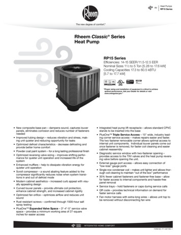
4. Tap collar (if necessary) to ensure engagement withunit opening and install second screw.5. Tighten first screw and rotate collar clockwise so jointis near three o’clock position.Return Duct1. Assemble the collar by overlapping the two ends.NOTE: One end of the collar is slotted and the oppositeend has two small holes. Position the end with smallscrew holes underneath the slotted end.2. Fasten the collar ends with two self drilling sheet metalscrews.3. Position the collar over the unit opening. Align thefour holes in the collar with the four dimples or holes(depending on unit model) in the panel.4. Secure the collar to the rear panel using self drillingscrews (10-16x.5).Locating & Installing the Return Air AssemblyTo simplify installation, locate and install the return airassembly first. If desired, the return opening can belocated inside a closet with louvered doors that has anopen area equal to or greater than a 12” x 20” grille. Thereturn air grille can be placed in the wall of a closet andthe air ducted into the filter box through a boxed-in areaat the closet floor level (Figure 5). Verify the filter isreadily accessible.the floor. However, if the floor is more than ten inchesdeep, it will only be necessary to cut a hole for the collaron the return air box or for the insulated duct.3. Set the box into the opening and fasten with screws ornails.4. Install the filter and return air grille in the air box.Connecting the Return & Supply Air Flexible Ducts Flexible ducts can be connected to the correspondingfittings with the clamps provided with the ducts. SeeFigure 10 (page 13). NOTE: To prevent a loss in coolingcapacity, make sure all connections are tight. The flexible ducts may be cut to the required length,see instructions packed with duct. Keep all ducts asshort and straight as possible. Avoid sharp bends. Ducts may be spliced with sheet metal sleeves andclamps. After the inner duct is connected to the proper fitting,the insulation and plastic sleeve should be pulled overthe connection and clamped. Homes with multiple supply ducts (or specialapplications), a Y fitting is available to divide thesupply air so it can be ducted to different areas of thehome for more efficient cooling. NOTE: For maximumperformance, insulate the Y fitting.Locating & Installing the Supply Damper(s)NOTE: The return air box with grille and filter should notbe located in heavy traffic areas like hallways or centerof rooms. A good spot is in a corner or under a table, if aminimum two inch clearance is available.1. Start the installation from under the home by cutting asmall hole in the subfloor. Determine how the floor joistlocation will affect cutting the opening needed for thereturn air box. NOTE: Floor joists are generally locatedon 16” centers, leaving 14-3/8” between joists.2. After measuring the return air box (approximately 121/4” x 20-1/4”), cut the hole through the floor so thatthe box will fit between the floor joists. Care should betaken when cutting through carpeting to avoid snags.NOTE: In most installations it will be necessary to cut asimilar hole in the fiberboard directly under the hole inCAUTION:If installing this air conditioning system inconjunction with a furnace, a damper mustbe installed in the furnace base assemblyto prevent cold air from being dischargedaround the heat exchanger. Damage to theheat exchanger and asphyxiation may occur ifa damper is not installed.Check with the furnace manufacturer for damperrequirements. Failure to install the requiredfurnace damper may invalidate code agencylisting and limited warranty on the furnace.When locating the supply damper(s), carefully checkfloor joists and frame members that could interfere withthe installation of the damper or flexible duct. Ideally, thedamper (Figure 6, page 8) should be located in the bottomof the main duct, forward of center of the home, at leastthree feet from the nearest register. The round supplyopening in the slanted side of the damper should facethe side of the home where the air conditioner is located.Figure 5. Return Air Box1. Locate the center of the heat duct by cutting a smallhole in the fiberboard below the duct at the desiredlocation.2. Cut a hole approximately 3/4” larger than the damperopening in the fiberboard.7
3. Cut a 9-1/8” x 13-1/8” hole in the duct and bend overall tabs flat on the inside of the heat duct.4. Insert the damper into the duct and bend over all tabsflat on the inside of the heat duct.5. Seal the opening between the fiberboard and damperor flexible duct.ELECTRICAL CONNECTIONSWARNING:To avoid risk of electrical shock, personalinjury, or death, disconnect all electrical powerto the unit before performing any maintenanceor service. The unit may have more than oneelectrical supply.Label all wires prior to disconnection whenservicing the unit. Wiring errors can causeimproper and dangerous operationFigure 6. Supply DamperCondensate DrainageA 3/4” condensate fitting extends out of the side of theunit (Figure 7). The drain trap, shipped in the electricalcompartment, must be installed to prevent water fromcollecting inside the unit.1. Thread the elbow provided with the unit into the drainconnection until hand tight.2. Connect the condensate tubing onto the fitting, forminga trap near the drain connection.3. Route the condensate tube from the trap to a suitabledrain. NOTE: For proper drainage, make sure the trap islevel to the ground and tubing outlet is below trap level.ElbowP-TrapFigure 7. Drain TrapLine VoltageLow VoltageFigure 8. Power Entry8 All electrical connections must be in compliance withall applicable local codes and ordinances, and withthe current revision of the National Electric Code(ANSI/NFPA 70). For Canadian installations the electrical connectionsand grounding shall comply with the current CanadianElectrical Code (CSA C22.1 and/or local codes).Pre-Electrical Checklist Verify that the voltage, frequency, and phase of thesupply source match the specifications on the unitrating plate. Verify that the service provided by the utility is sufficientto handle the additional load imposed by this equipment.Refer to the unit wiring label for proper high and lowvoltage wiring. Verify factory wiring is in accordance with the unit wiringdiagram (Figures 11 or 12, pages 14 - 15). Inspect forloose connections.Line Voltage A wiring diagram is located on the inside cover of theelectrical box of the unit. The installer should becomefamiliar with the wiring diagram before making anyelectrical connections to the unit. An electrical disconnect must be located withinsight of and readily accessible to the unit. Thisswitch shall be capable of electrically de-energizingthe unit. Line voltage to the unit should be supplied from adedicated branch circuit containing the correct fuseor circuit breaker for the unit. Incoming field wiringand minimum size of electrical conductors and circuitprotection must be in compliance with information listedon the unit data label. Any other wiring methods mustbe acceptable to authority having jurisdiction. Provide power supply for the unit in accordance with theunit wiring diagram, and the unit rating plate. Connectthe line-voltage leads to the terminals on the contactorinside the control compartment. Extend leads throughpower wiring hole (Figure 8). Connect L1 & L2 directlyto the contactor.
The unit requires both power and control circuit electricalconnections. Refer to the wiring diagram / schematic(Figures 11 & 12, pages 14 & 15) for identification andlocation of unit field wiring interfaces. Make all electricalconnections in accordance with all applicable codesand ordinances. Overcurrent protection must be provided at the branchcircuit distribution panel and sized as shown on the unitrating label and according to applicable local codes.See the unit rating plate for minimum circuit ampacityand maximum overcurrent protection limits. Use only copper wire for the line voltage power supplyto this unit as listed in Table 1. Use proper code agencylisted conduit and a conduit connector for connectingthe supply wires to the unit. Use of rain tight conduit isrecommended. 208/230 Volt units are shipped from the factory wiredfor 230 volt operation. For 208V operation, remove thelead from the transformer terminal marked 240V andconnect it to the terminal marked 208V. Optional equipment requiring connection to the poweror control circuits must be wired in strict accordance ofthe NEC (ANSI/NFPA 70), applicable local codes, andthe instructions provided with the equipment.Overcurrent ProtectionGenerally, the best fuse or breaker for any air conditioneris the smallest size that will permit the equipment to rununder normal usage and provide maximum equipmentprotection. Properly sized fuses and breakers also preventnuisance trips during unit startup. If a fuse blows or abreaker trips, always determine the reason. Do notarbitrarily install a larger fuse or breaker and do not,in any case, exceed the maximum size listed on thedata label of the unit.COPPER WIRE SIZE — AWG(1% Voltage Drop)Supply Wire 35014121010886664Supply CircuitAmpacity15202530354045505560Wire Size based on N.E.C. for 60 type copper conductors.Table 1. Copper Wire SizeGroundingWARNING:The unit cabinet must have an uninterruptedor unbroken electrical ground to minimizepersonal injury if an electrical fault should occur.Do not use gas piping as an electrical ground!This unit must be electrically grounded in accordancewith local codes or, in the absence of local codes, with theNational Electrical Code (ANSI/NFPA 70) or CSA C22.1Electrical Code. Ground the air conditioning unit usingthe green grounding screw provided in the control panel.Thermostat / Low Voltage Connections The unit is designed to operate from a 24 VAC ClassII control circuit. The control circuit wiring must complywith the current provisions of the NEC (ANSI/NFPA70) and with applicable local codes having jurisdiction.Thermostat connections should be made in accordancewith the instructions supplied with the thermostat andthe indoor equipment. The low voltage wires must be properly connected. Route24V control wires through the sealing grommet (Figure8, page 8) near the power entrance. Recommendedwire gauge and wire lengths for typical thermostatconnections are listed in Table 2 (page 10). Single stage or two-stage thermostats can be usedwith this equipment depending on optional accessories(
TROUBLESHOOTING If the unit fails to operate, check the following: Check the thermostat setting. Make sure the system mode and temperature settings are correct. Check the electrical panel for tripped circuit breakers. Check the fi lters for dust accumulation. Check the unit and make sure it is clean and not covered