Transcription
GSJ: Volume 8, Issue 3, March 2020ISSN 2320-9186831GSJ: Volume 8, Issue 3, March 2020, Online: ISSN 2320-9186www.globalscientificjournal.comDesign and Simulation of a Multi Tank Water LevelControllerSunny Orike ; Folorunsho M. Odeyemi and Magnus E. Obasi.magem2all@gmail.com,ABSTRACT:In this study, a multi-tank water level controllerwas developed using the Arduino Nanomicrocontroller board as the PLC of the system.The use of this PLC allowed for flexibility ofcontrol, display and reduction of human inferencein operating the system. A hydrostatic pressurebased approach was adopted in measuring thevolume of liquid in each of the six tanks. SixMPX4115 pressure sensors were used in obtainingthe pressure in the tanks. The outputs of thesesensors are fed to the analog input of the ArduinoNano (PLC). These inputs are calibrated to a scaleof 100% to give the volume of liquid in the tanks.The volume of liquid in each individual tank isused in controlling the supply valve of that tankwhen filling. When the volume of liquid in a tank isless than 80%, the valve is opened to allow forfilling, and closed at 80% full. The volume of eachof the six tanks is summed to give the volume ofliquid in the entire system. This volume controlsthe borehole pumping machine.Keywords: Programmable Logic Controller (PLC),Arduino Nano, Multi tank, Water level controller,MPX 4115.1.INTRODUCTION:Basic tank water level control utilizes 2 controlcircuit switches; one low water level switches thatmakes to ON the filling borehole pump and onehigh water level switch that breaks contact to shutOFF the borehole pump power source. With thiscontrol, the level and volume of water in the tankbetween these two control points is not known.This simple design is ideal for a one-water Tanksystem, consequently, this water tank must besufficiently big to meet the estate or building’swater demand.Because conventional storage waterlevel control assumes that the storage unit is ONEtank, most estate now resort to manual operation inrefilling of the water in a multi-tank utility system.This project aims to control the water inflow andstorage in 2-8 tanks using one Arduino Nanoprogrammable logic controller.The level in eachtank is calculated by sensing the pressure due tothe height of water column, that is, the hydrostaticpressure head of the water column. Each tank willhave a 0 -3psig MPX4115 pressure sensor attachedto it at the base to sense the hydrostatic pressuredue to the water height within the tank.With thepressure sensed and inputted as a voltage signalinto the analogue input of the Programmable LogicController (PLC), the height of water in thatGSJ 2020www.globalscientificjournal.com
GSJ: Volume 8, Issue 3, March 2020ISSN 2320-9186832particular tank and hence its volume is calculatedand displayed as a percentage.Several attempts have been made by previousresearchers in developing tank water level controlsystems.Anyanwu (2012) in his work used MC14066integrated circuit to realize automatic regulatorsuitable for water level sensing and control. Thiswater level sensor was tested in real timeapplication by using it to control the level of waterin a tank fed by a single phase 0.5 HP AC pump.This system recorded inaccurate volumecalculation and display due to limited sensorcapabilities.Again, it is still limited to one tank persensor per Arduino.In the works of Asaad et al. (2013), Arduino wasused in automating the process of water pumpinginto a tank by detecting the level of water in thetank per time using a floating water level sensor.This sensor was designed out of a floating materialattached to the arm of a potentiometer. The systemhad the ability to detect the level of water in a tank,switch on or off the pump accordingly and displaythe status on an LCD screen.This system waslimited to 12v pumps therefore making itunsuitable for industrial or domestic application.Erua & Anyasi (2014), developed a closed loopautomatic water level controller using a mercuryfloat sensor. Their system incorporates two mainscontactors which are energized to provide a directonline start of the motor. An over load relay whichsenses the presence of excess current anddisconnect the supply and a mercury flood switchwhich uses the Archimedes principle of floatationto provide the electrical contact to switch ON orOFF supply to the motor when the tank is empty orfull respectively. This was capable of providing aseamless utilization of water at domestic andindustrial level without causing spillage. Thiscontroller is not feasible for application inresidential homes as the mercury float sensor usedis expensive and not readily available.Yuriy et al. (2015) designed a PLC based system tocontrol liquid level by using Radar sensorremotely. This system measures the liquid level,volume, temperature, and pressure and controlsthese measurements remotely. The system consistsof the Radar sensor, temperature sensors, discretelevel sensors and a programmable logic controller.Alam (2016), developed an Automated WaterPump Controller (AWPC). This system used threewater level sensors to monitor the water level ofboth the ground-level water reservoir and therooftop residential water tank. Once the supply ofwater decreases down to a point of concern,roughly 10% of the tank capacity, the controllerturns off the water pump. This prevented the waterpump from siphoning air which can result in thewater pump’s malfunction or complete breakdown.Similarly, the controller turned off the water pumpwhen the rooftop tank reached a water level ofgreater than or equal to 95%. This prevented thetank from overflowing and wasting water.Considering the works of previous researchersreviewed in this chapter, the automatic water levelcontroller and pump controllers developed thus farfail to address the issues of presenting a graphicindication or display of the volumetric amount ofwater present in the tank being studied orcontrolled per time. They also failed to developwater level controller systems which could beapplied in a multi-tank system where the pump andfilling of the different tanks is dependent on thecollective average volume of water in all tanks andindependent of the level of water in another tankrespectively.This project looks at automating the water fillingand availability aspect. It provides a system thatcan measure, to reasonable accuracy, the quantityof water used by a small community.The systemdesigned in this work is one which intends to solvethe afore mentioned challenges by developing amulti-tank water level controller, which caneffectively control the pump (supply) of water tosix tanks. This is to be based on the cumulativeaverage volume of water in all six tanks. Also, inthis system, filling of each tank is independent ofanother tank as separate valves are to be used incontrolling the supply of water into each tank. Thiswork intends to achieve this using an ArduinoNano, six MPA4115 pressure sensors, a pump, andsix/eight valves. This work is to be designed andsimulated on the Proteus professional Suiteenvironment, with the program governing thesystem developed on the Arduino IDE.2.MATERIALS AND METHODS:The volume of liquid in a vessel of measure leveldepends solely on the shape of the vessel. For theGSJ 2020www.globalscientificjournal.com
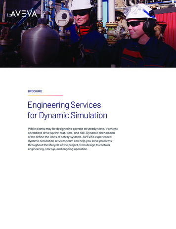
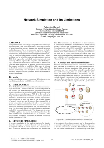
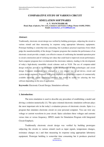
GSJ: Volume 8, Issue 3, March 2020ISSN 2320-9186833proposed study, cylindrical water Tank is assumedto be used. A typical tank used for water storage inNigeria is cylindrical in shape and has height of upto 8 feet.Considering a typical tank as shown in Fig 1,Mathematically, therefore, the volume of water Vin the tank will be𝑉𝑉 ℎ 𝜋𝜋 R2(1)Where h is the height/level of water in tank, π is3.142 and R is the Radius of the cylindrical tank.Since R, radius of tank and π are constants, thevolume therefore varies directly with theheight/level.Putting ℎ 𝑝𝑝/ρ𝑔𝑔 in equation 3.3 will give𝑉𝑉 𝑝𝑝 𝜋𝜋 R2 /𝑔𝑔(2)Fig 1:Pressure Exacted at the Base of a Containerwith Liquid Level h.2.1 Mathematical Model for Tank waterinflow/outflow.Modeling of a real time cylindrical tank whichexhibit non linearity property will be considered inthis research work.This mathematical model of a cylindrical tank isgotten by considering two variables namely; thecontrol variable and the manipulated variable.While our desired level will be the controlvariable, the manipulated level is the inflow to thetank. We can get this by controlling the input flowsto the tank.Fig 2:Pressure due to liquid column of height HGiven;A πr 2 cross sectional area of our cylindricaltankV πr 2 ℎ volume f the tankQ1 Input flow rateQ2 outlet flow rate.H Height of water in the tank.h Desired height of water in the tank.g Acceleration due to gravity.C1 Valve coefficientCA coefficient of desired height.From the law of conservation of matter, we can saythat;Rate of accumulation of mass in the tank massinflow – mass outflow.𝑑𝑑𝑑𝑑 𝑄𝑄1 �� 𝑑𝑑𝑑𝑑 𝑄𝑄1 𝑄𝑄2(4)The outlet flow rate of the cylindrical tank is givenby the Torricelli’s law which states that the speedor the outflow of a fluid through an edge hole atthe bottom of a tank filled to a depth is the same asthe speed that a body would acquire in fallingfreely from a height ‘h’.HenceQ 2gh(5)With respect to the size and shape of the valve, theoutflow is given by𝑄𝑄2 C2 2gh(6)Putting equation 3.6 into 3.4 gives𝑑𝑑𝑑𝑑𝐴𝐴 𝑑𝑑𝑑𝑑 𝑄𝑄1 C2 2gh(7)In steady state, we know that𝑑𝑑𝑑𝑑 0(8)𝑑𝑑𝑑𝑑Q1 Q 2(9)That is that inlet flow outlet flowGSJ 2020www.globalscientificjournal.com
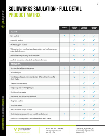
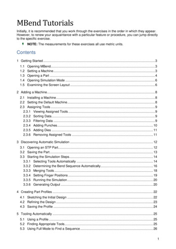
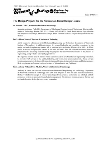
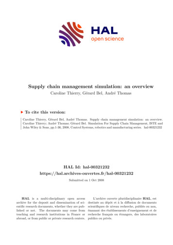
GSJ: Volume 8, Issue 3, March 2020ISSN 2320-9186834To linearize equation 3.4, around the desiredheight, the out-flow equation can be linearized.And equation 3.6 is rewritten approximately as:𝑄𝑄2𝐶𝐶 𝑎𝑎 2 𝑐𝑐1(10)2gH 2𝑔𝑔ℎ𝑄𝑄2 𝑐𝑐1 2𝑔𝑔𝑔𝑔(11)𝑑𝑑𝑑𝑑𝐴𝐴 𝑑𝑑𝑑𝑑 𝑄𝑄1 𝐶𝐶1 2𝑔𝑔𝑔𝑔Dividing through by A𝑑𝑑𝑑𝑑𝑄𝑄𝐶𝐶 2𝑔𝑔𝑔𝑔 𝐴𝐴1 1 𝐴𝐴𝑑𝑑𝑑𝑑Where𝐶𝐶 𝑎𝑎𝐶𝐶1 1 ��2 𝐼𝐼𝑚𝑚𝑚𝑚𝑚𝑚2p pressure in liquid (N/m , Pa, lbf/ft , psi)ρ density of liquid (kg/m3, slugs/ft3)g acceleration of gravity (9.81 m/s2, 32.17405ft/s2)(12)h height of fluid column - or depth in the fluidwhere pressure is measured (m, ft).For the purpose of this work, a MPX4115 pressuresensor is used.(13)MPX4115 pressure Sensor(14)This is an integrated Silicon Pressure Sensordesigned to sense pressure in an altimeter orbarometer (BAP) application. In interfacing thesensor to the Arduino Nano, only three pins arerequired. Pins 1, 2, and 3. Pin 1 is connected to anADC pin of the Arduino Nano, pin 2 connected tothe common GND and pin 3 to the 5V output ofthe Arduino Nano. In this work, six of this sensorare required to determine the pressure in all sixtanks. The connection of the six sensors to theArduino ADC pins is shown in Fig 3.(15)𝐼𝐼𝑎𝑎𝑎𝑎𝑎𝑎 ���𝑚𝑚 ��𝑚𝑚𝑚𝑚Substituting C1 and C2 into equation 3.13𝑑𝑑𝑑𝑑𝑄𝑄a 𝐼𝐼𝑎𝑎𝑎𝑎𝑎𝑎 2𝑔𝑔𝑔𝑔 𝐴𝐴1 (16)𝑑𝑑𝑑𝑑 2𝑔𝑔ℎ 𝐴𝐴 𝐼𝐼𝑚𝑚𝑚𝑚𝑚𝑚2.2 Circuit Components and DesignThe multi tank water level controller designed inthis work consists of an Arduino Nano PLC board,a MA4115 pressure sensors, a 16 X 2 LCD screen,six 5V DC low trigger relays, 2N3904 NPNtransistors, IN4007 diodes and a 5V DC powersource. This design was executed on the Proteus 8professional design suit.i.Pressure Sensors/Transducers.A Transducer is a device that converts variations ina physical quantity, such as pressure or brightness,into an electrical signal. This study is aim atmeasuring Tank volume by it liquid level/heightand this height is calculated based on the pressurea known column height of liquid will exert at thetank base.Consequently, the Transducer chosen for thisproject is a differential pressure transducer.Considering Fig 1 and relating to storage tankliquid (water) level measurement, Hydrostaticpressure p can be calculated asp ρghWhere2Fig 3: MPX 4115 Arduino Connection.ii.RelayIn order to effectively control the filling of the sixtanks, relays are used in cutting off voltage supplyto the supply valves of the tanks and also incontrolling the switching ON and OFF of the pumpbased on the average percentage water volume inall six tanks. A total of seven relays are used. Sixfor controlling the valves of the tanks and one forcontrolling the pump actuation. These relaysrequire a driver circuit in order to operate thus,IN4007 diodes and 2N3904 NPN transistors areused in driving/controlling the relays from theGSJ 2020www.globalscientificjournal.com
GSJ: Volume 8, Issue 3, March 2020ISSN 2320-9186835Arduino digital output pins. The relay/Valve drivercircuit is shown in Fig 4.The Arduino Nano is a Programmable logiccontroller with an onboard ATMega 328microcontroller IC chip. The Arduino Nano servesas the main processor in this design. It isresponsible for interpreting and calibrating analoginputs from the pressure sensors, performing theactuations on the valve and pump and alsocontrolling the Display of the LCD.v.Proteus 8.7 SP3 ProfessionalThis is a version of the Proteus Design suitedeveloped by Labcenter Electronics. It is widelyused for electrical schematic design, PCB layoutdesign and Virtual simulation. This softwareapplication is chosen for the purpose of this workdue to its user friendly interface, vast Library ofcomponents, Virtual Terminal display and realtime simulation. The entire circuit is designed onthis platform. With each individual componentpicked form the component library. The completecircuit designed on Proteus can be seen in Fig. 6.Fig 4: Valve Control Circuitiii.16 x 2 Liquid Crystal Display ScreenThis is a Liquid Crystal Display (LCD) screenconsisting of two rows and sixteen columns. TheLCD is used in displaying combined average waterlevel in all six tanks. The LCD has 16 pins and isconnected to the Arduino Nano as shown in Fig 5.Fig 6.Multi-Tank Water Level Controller Circuit.Fig 5Display Circuit Connectioniv.Arduino Nanovi.Arduino IDE and Software DesignThe program which governing the entire system isdeveloped on the Arduino IDE (IntegratedDevelopment Environment) in the form of sketcheswritten in C programming language. Thecomplete Sketch is compiled using the AVRISPmkii programmer in the IDE. The compiled codewhich is then uploaded to the ATmega 328 throughthe Arduino Nano.In developing the program, pins are first declaredfor the Pressure sensors with storage memoryGSJ 2020www.globalscientificjournal.com
GSJ: Volume 8, Issue 3, March 2020ISSN 2320-9186836locations assigned to each pin these locations areused in storing the analog data from the pressuresensors. A maximum integer size is set at 1023 anda minimum set at 0, the LCD library is called 67810826.278.50.7850.77511.4Pressureand pins assigned to the LCD. Other memorylocations are assigned and the valve pins assigned.The valve pins are set on OUTPUT mode(pinMode, valvepin, OUTPUT) and serialcommunication is initiated at 9600Bps. The analoginput from the pressure sensor is calibrated from 01023 to 0-100%. The flow structure is designedsuch that the for tank level less than 80%, the tankvalves are left open otherwise they are closed. Thewater level in all six tanks are averaged anddisplayed on the LCD screen. If this average fallsbelow 20%, the water pump is turned ON andpumped till the average is at 80%.Fig 7: Block Diagram of Water Tank LevelControl System.3.RESULTS AND DISCUSSION:The result of the calculated hydrostatic pressurecalculated for water up to 8meters is shown intable 4.1.Table 1: Hydrostatic pressure for water column upto 8meters.Having designed the multi-tank water level circuiton Proteus and the program file uploaded to theArduino Nano in the worksheet, the worksheet isrun and the characteristics behaviour of the systemGSJ 2020www.globalscientificjournal.com
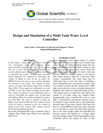
GSJ: Volume 8, Issue 3, March 2020ISSN 2320-9186837observed. The results of this simulation arepresented in Fig. 8,9,10, and 11Fig 10: Virtual Terminal Display of Water Levelin Each Tank.Fig 8: Simulation of Multi-Tank Water LevelControllerFig 11: Pressure Sensor showing the Pressure(KPa) in each TankFig 9: LCD showing Cumulative Average waterlevel.From the results obtained from the simulation ofthe multi-tank water level controller, it can beobserved that the pressure measured in each tankby the pressure sensors is converted to a scale of100%. When the pressure in Tank 1 is increased byclicking the arrow key pointing upwards in Fig 11,the percentage water level in tank 1 is increased ascan be observed on the virtual terminal as shown inFig 10. Thus, any change in the pressure in thetank results in an equivalent change in the tankwater level on the virtual terminal. Thus, thepressure sensors are able to accurately measure anddisplay the volume of water per time in the storagetanks.In Fig 9, the LCD is observed to display“SUMTOTAL 78%”, and “SUMTOTAL 81%.GSJ 2020www.globalscientificjournal.com
GSJ: Volume 8, Issue 3, March 2020ISSN 2320-9186838PUMP OFF”. This percentage value is thecumulative average of the water levels in all sixtanks. It is observed that, when the water level inany of the tanks is less than 80%, the valvecontrolling the supply of water to that tank isswitched to the NO (Normally Open) configurationotherwise. When the cumulative pressure in all sixtanks drop to or falls below 20%, the water pumpis turned ON until the average is back to 80%.Thus, through the use of the Arduino Nano, analoginputs from the different pressure sensors on thedifferent tanks are able to calculate the individualvolume of each tank and sum the total cumulativeaverage volume of all the tanks. This cumulativeaverage is used in initiating a START and STOPsignal to the borehole pumps.4.CONCLUSIONAutomatic water level controllers are devices thatare used in controlling the volume of water ofliquid in a tank. These devices make use of variousmethods in determining the volume of water orliquid in the tank. In this study, a multi-tank waterlevel controller was developedusing the ArduinoNano microcontroller board as the PLC of thesystem. The use of this PLC allowed for flexibilityof control, display and reduction of humaninference in operating the system. A pressure basedapproach was adopted in measuring the volume ofliquid in each of the six tanks. Six MPX4115pressure sensors were used in obtaining thepressure in the tanks. The outputs of these sensorsare fed to the analog input of the Arduino Nano(PLC). These inputs are calibrated to a scale of100% to give the volume of liquid in the tanks.The volume of liquid in each individual tank isused in controlling the supply valve of that tank.When the volume of liquid in a tank is less than80%, the valve is opened to allow for supply, andclosed at 80% full. The volume of each of the sixtanks is summed to give the volume of liquid in theentire system. This volume controls the boreholepumping machine.The system was able to satisfy all of its intendedaim and objectives as can be seen in the resultsobtained when the system is RUN.5.ACKNOWLEDGEMENT:The acknowledgments of people who providedassistance in manuscript preparation, funding forresearch etc., should be listed in this section. Allsources of funding should be declared as anacknowledgement. Authors should declare the roleof funding agency.REFERENCESAjinkya, K., & Milind, R. (2017). AutomaticWater Level Indicator & Controller (Tocontrol water level of overhead tank). csandCommunication Engineering (IJARECE),1289-1290.Alam, D., Salguero, G., & Kyle, R. M. (2016).Automatic Water Pump Controller . SanLuis Obispo: California Polytechnic StateUniversity.Anyanwu , C. N., Mbajiorgu, C. C., & Anoliefo, E.C. (2012). Design And Implementation OfA Water Level Controller. Nigerian Journalof Technology (NIJOTECH) Vol. 31, No.1.Anyanwu, C., Mbajiorgub, C., & Anoliefod, E.(2012). Design and Implementation of aWater Level Controller, 31(1). NigerianJournal of Technology (NIJOTECH). 30(1),89-92.Asaad, A., Mohammed, A. E., & Zhang, J. M.(2013). Automatic Water Level ControlSystem. . International Journal of Scienceand Research (IJSR) ISSN (Online): 23197064, 5.Bossart, E. (2014, December 11). Fundamentals ofhydrostatic level measurement. d/TA 1114 IDM en co 63032.pdfErua, J., & Anyasi, F. I. (2014). Design of anAutomatic Water Level Controller UsingMercury Float Switch. IOSR Journal ofGSJ 2020www.globalscientificjournal.com
GSJ: Volume 8, Issue 3, March 2020ISSN 2320-9186839ElectronicsandCommunicationEngineering (IOSR-JECE) 9(2), 22782834.Ishwar, C. M., & Laloo, K. Y. (2013). Low CostAutomatic Water Level Control forDomestic Application. Rourkela: NationalInstitute of Technology .Mashud, M., Hoque, E., & Serajul, I. (2011).Design and Implementation of a SinglePhase Water-Pump Controller . Dhaka,Bangladesh: Institute of Electronics,Atomic Energy Research Establishment,.Oyndrila, R., Aranyak, R., & Debasis, R. (2016).AUTOMATICWATERLEVELINDICATOR. . International Journal ofEmerging Trends in Engineering andDevelopment Issue 6(2, 2249-6149.GSJ 2020www.globalscientificjournal.com
programmable logic controller.The level in each tank is calculated by sensing the pressure due to the height of water column, that is, the hydrostatic pressure head of the water column. Each tank will have a 0 -3psig MPX4115 pressure sensor attached to it at the base to sense the hydrostatic pressure due to the water height within the tank.With the