Transcription
Research Articlewww.acsami.orgLight-Directed Self-Assembly of Robust Alginate Gels at PreciseLocations in Microfluidic ChannelsHyuntaek Oh,† Annie Xi Lu,† Vishal Javvaji,† Don L. DeVoe,‡ and Srinivasa R. Raghavan*,††Department of Chemical and Biomolecular Engineering and ‡Department of Mechanical Engineering, University of Maryland,College Park, Maryland 20742, United StatesS Supporting Information*ABSTRACT: Recently there has been much interest in usinglight to activate self-assembly of molecules in a fluid, leading togelation. The advantage of light over other stimuli lies in itsspatial selectivity, i.e., its ability to be directed at a preciselocation, which could be particularly useful in microfluidicapplications. However, existing light-responsive fluids are notsuitable for these purposes since they do not convert intosufficiently strong gels that can withstand shear. Here, weaddress this deficiency by developing a new light-responsivesystem based on the well-known polysaccharide, alginate. Thefluid is composed entirely of commercially availablecomponents: alginate, a photoacid generator (PAG), and achelated complex of divalent strontium (Sr2 ) cations. Upon exposure to ultraviolet (UV) light, the PAG dissociates to release H ions, which in turn induce the release of free Sr2 from the chelate. The Sr2 ions self-assemble with the alginate chains to give astiff gel with an elastic modulus 2000 Pa and a yield stress 400 Pa (this gel is strong enough to be picked up and held by one’sfingers). The above fluid is sent through a network of microchannels and a short segment of a specific channel is exposed to UVlight. At that point, the fluid is locally transformed into a strong gel in a few minutes, and the resulting gel blocks the flow throughthat channel while other channels remain open. When the UV light is removed, the gel is gradually diluted by the flow and thechannel reopens. We have thus demonstrated a remote-controlled fluidic valve that can be closed by shining light and reopenedwhen the light is removed. In addition, we also show that light-induced gelation of our alginate fluid can be used to depositbiocompatible payloads at specific addresses within a microchannel.KEYWORDS: photorheological fluid, photoresponsive self-assembly, microfluidic valve, photodeposition, ionic cross-linking within a network of fluidic channels can be closed andreopened as needed.Despite many recent advances, PR fluids are not used inapplications such as the one described above. There are manyreasons for this. One major bottleneck that used to exist withPR fluid formulations is that they used to be based on complexphotoresponsive molecules that needed to be synthesized forthe purpose. Examples of such molecules include surfactants,8 12 salts,13 15 polymers,16 18 or small-molecule gelators19 21 that contain photoresponsive azobenzene, stilbene, orspiropyran moieties. In the past few years, however, ourlab22 29 and others30 32 have developed PR fluids basedentirely on simple, commercially available components (nosynthesis required). For example, we recently demonstrated asurfactant-based PR fluid that shows a million-fold increase inits zero-shear viscosity under ultraviolet (UV) light and adecrease back to its original viscosity under visible light.29INTRODUCTIONFluids whose rheological properties can be remotely controlledby external fields have fascinated scientists and engineers. Thefirst examples of such fluids date back to the 1940s and focusedon rheology modulation via electric or magnetic fields, with thecorresponding fluids being termed electrorheological (ER) andmagnetorheological (MR) fluids, respectively.1 4 Since thattime, a wide range of applications have been envisioned for ERand MR fluids in mechanical devices such as dampers, clutches,and valves, some of which have been practically realized.4,5Recently, light has emerged as a different remote trigger forrheology modulation. Fluids with light-tunable rheology aretermed photorheological (PR) fluids.6 Light as an externaltrigger has many advantages over other fields or stimuli: it canbe directed from a distance at a precise location with aresolution of few microns, and a wide range of light sources areavailable with distinct wavelengths and intensities. A potentialapplication of PR fluids that would leverage the spatialselectivity of light is in making a light-activated valve for flowcontrol within microfluidic or nanofluidic devices.7 The idea isthat, by using light as an external switch, specific flow paths 2016 American Chemical SocietyReceived: March 30, 2016Accepted: June 9, 2016Published: June 27, 201617529DOI: 10.1021/acsami.6b03826ACS Appl. Mater. Interfaces 2016, 8, 17529 17538
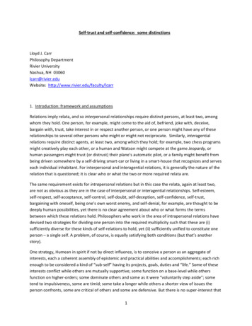
Research ArticleACS Applied Materials & InterfacesFigure 1. Comparing the rheology of two types of PR fluids. In both cases, initially, i.e., before UV irradiation, the sample is a low-viscosityNewtonian fluid. (a) Upon exposure to UV light, the sample attains a high, but finite low-shear viscosity followed by a decrease in viscosity underhigher shear (shear-thinning). Thus, the ratio of viscosities at a stress σ 50 Pa is only 100 . (b) Upon exposure to UV light, the sample becomesa gel with a yield stress σy 100 Pa, i.e., the viscosity is practically infinite for σ σy. As a result, at σ 50 Pa, the sample does not flow at all. Theresponse in (b) is desirable for flow-blocking applications.These simpler systems have made PR fluids accessible to manymore researchers, which is expected to facilitate applications.While the accessibility problem has been potentially solved,other issues remain. One issue for applications in microscaledevices is that fluids in these devices can be subjected to veryhigh shear rates (due to the small dimensions of thechannels).33,34 At these high shear rates, the PR effect isreduced, i.e., the light-induced change in viscosity tends to beinsufficient to affect the flow. The problem arises because thehigh-viscosity state of all PR fluids relies on physical(noncovalent) bonds, i.e., on self-assembly.11,19 These physicalbonds tend to get disrupted when the fluid is sheared and reform when shear is ceased. For this reason, PR fluids tend toshow significant shear-thinning, i.e., a sharp decrease in theirviscosity as a function of shear rate or shear-stress (Figure1a).35,36 Consequently, the light-induced change in viscosity athigh shear may be small (only a factor of 10 to 100) eventhough this change is substantial (factor of 1000 or more) atlow shear, as shown in Figure 1a.A further issue has to do with the time scale of light-inducedrheological changes, i.e., the response time. Most PR fluidsrequire relatively long irradiation times (more than 10 min) toinduce a large change in viscosity, even when a high-power UVlamp ( 100 W) is used. The response time is shorter forsmaller sample volumes, i.e., it seems to depend mainly on thepath length traversed by the light.22,26 Thus, the response timesfor samples in microchannels (nL volumes) is expected to bemuch less than that for macroscopic samples in vials (mLvolumes). However, if the fluid in the microchannel is flowingwhile being irradiated at a specific point, the response timebecomes even more critical. That is, the sample rheology mustbe transformed quickly before fresh sample is brought to theirradiation point by the flow. Also, the pressure exerted by theflow will counteract the buildup of a viscoelastic plug. Thus, inorder to block the flow and withstand the pressure buildup,there must be a rapid and substantial change in the fluidrheology.In this paper, we develop a new PR fluid that can be used in alight-activated fluidic valve. Our new formulation addresses theissues detailed above. The fluid is converted by UV light from athin liquid (sol) into a strong gel, and this conversion occursrelatively quickly. When this fluid flows through a network ofmicrochannels, we can block the flow through a specificchannel by irradiating a point in that channel with UV light for 3 min. We show that the key to blocking the flow is the elasticcharacter of the gel, as measured by its elastic modulus G′ andits yield stress σy. Note that the viscosity of a gel, i.e., a materialwith a yield stress, is essentially infinite below the yieldstress.34,35 That is, a gel has an infinite relaxation time andviscosity, whereas these are both finite in the case of aviscoelastic fluid.34,35 The importance of the yield stress isindicated by Figure 1b, i.e., for a fluid to block the flow, itshould have a sufficient yield stress. Indeed, this point is wellknown to scientists working on ER and MR fluids, who thusseek to maximize the yield stress under an electric or magneticfield.4,37 Likewise, PR fluids need to exhibit substantial σy valuesin their gel state to be usable in flow-blocking applications (i.e.,valves, clutches, and dampers).How does one create a PR fluid that is based on simplecomponents and yet gives a strong gel with a high yield stress?We ruled out micellar PR fluids because these generally formviscoelastic fluids and not gels.11,29 Small-molecule gelatorswith PR properties can exhibit yield stresses,19 21 but most ofthese systems require synthesis38 40 and the yield stresses arenot that high either. This leaves us with two candidates: PRfluids based either on nanoparticles24 or on polymers.26 Boththese have been developed in our lab and both form gels withyield stresses when irradiated with UV light, but the σy valuesare not that high ( 10 Pa). To provide a practical analogy,these were paste-like gels akin to ketchup; they were not freestanding solids, i.e., they could not be removed from theircontainer and gripped by tweezers or one’s fingers.In order to increase the yield stress, we turn to a polymericsystem based on sodium alginate. Alginate is a naturallyoccurring polysaccharide that is extensively used for cellencapsulation and other biomedical studies.41,42 Typically,alginate solutions are cross-linked into gels by adding divalentcations like calcium (Ca2 ) or strontium (Sr2 ). Recently,several researchers have devised strategies to induce gelation ofalginate by light.43 48 This has been done either by attachingphoto-cross-linkable groups to the alginate backbone43,44 or byphotoinduced release of divalent ions.45,46 Here, to make17530DOI: 10.1021/acsami.6b03826ACS Appl. Mater. Interfaces 2016, 8, 17529 17538
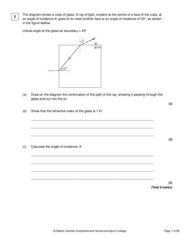
Research ArticleACS Applied Materials & Interfacesalginate solutions light-responsive, we use a class of moleculescalled photoacid generators (PAGs).49,50 The idea of usingPAGs to create light-responsive self-assemblies was firstreported by our lab24,26 and since then has been used byseveral researchers in a variety of systems.51 53 In our currentsystem, we combine alginate, a PAG, and a chelated complex ofSr2 ions to form a PR fluid. All these components arecommercially available. The concept is shown in Figure 2 and isdiscussed further below. The net result upon shining UV light isto form an alginate gel cross-linked by Sr2 ions, which is shownto exhibit σy 100 Pa. This gel is strong enough to be lifted offthe benchtop and held by one’s fingers (Figure 2c). Becauseour system offers simplicity (using only common chemicals), adramatic PR effect (from thin sol to strong gel), and a fastresponse (within a few minutes), we believe it will have wideutility. In addition to the fluidic valve, we also show a differentapplication with this system involving the use of light to depositpayloads at specific addresses along the walls of microchannels. EXPERIMENTAL SECTIONMaterials. Sodium alginate from brown algae (product number 400005) was purchased from Carbomer. The molecular weight wasspecified by the manufacturer to be around 500 kDa. Alginateextracted from algae usually contains impurities, and therefore itssolution is slightly turbid. To purify the alginate, it was dissolved inwater at 1 wt % and the solution pH was adjusted to around 10 withNaOH. Suspended impurities in the solution were removed byfiltration with Fisherbrand Glass Fiber Circles, grade G6, followed byprecipitation with acetone. The final purified alginate gave a clearsolution that was free of suspended impurities. The photoacidgenerator (PAG), diphenyliodonium nitrate, and methyl-β-cyclodextrin (m-β-CD) were purchased from TCI. The chelating agent,ethylene glycol tetraacetic acid, tetrasodium salt (EGTA), strontiumchloride (SrCl2), D-glucono-δ-lactone (GdL), and phenol red wereobtained from Sigma-Aldrich. Aqueous solutions of green fluorescentbeads (Fluoresbrite YG, 0.10 μm) and red fluorescent beads(Fluoresbrite Polychromatic Red, 0.5 μm) were purchased fromPolysciences. For all samples, deionized (DI) water was used.Sample Preparation. All samples were prepared by mixing stocksolutions of alginate, Sr-EGTA, and the PAG-CD complex. Thepurified alginate was dissolved at a concentration of 5 wt % in DI waterto make its stock solution. The Sr-EGTA solution was prepared bydissolving desired amounts of SrCl2 and EGTA at a EGTA:SrCl2molar ratio of 1.25. To prepare the solution of the PAG-CD complex,weighed amounts of PAG and m-β-CD were dissolved in DI water,and this solution was sonicated for 5 min. The molar ratio of m-βCD:PAG was fixed at 3. To make the PR fluids, equal volumes of theSr-EGTA and the PAG-CD stock solutions were first mixed, and tothis an equal volume of the alginate stock solution was added, followedby vortex mixing. The final concentration of alginate in the PR fluidswas 2.5 wt %. The pH of these fluids before light irradiation wasaround 8.0.Sample Response Before and After UV Irradiation. Sampleswere irradiated with UV light from an Oriel 200 W mercury arc lamp.A dichroic beam turner with a mirror reflectance range of 280 to 400nm was used to access the UV range of the emitted light. A filter forbelow 400 nm light was used to eliminate the undesired visiblewavelengths. Samples (2.5 mL) were placed in a Petri dish of 60 mmdiameter with a quartz cover, and irradiation was done for a specificduration without stirring.Rheological Studies. A TA Instruments AR2000 stress-controlledrheometer was used to perform steady and dynamic rheologicalexperiments. Samples were run at 25 C on a cone-and-plate geometry(40 mm diameter and 2 cone angle) or a parallel plate geometry (20mm diameter). A solvent trap was used to minimize drying of thesample during measurements. Dynamic frequency spectra wereFigure 2. Working principle of the PR fluid developed in this study.(a) The components are the biopolymer alginate, the Sr-EGTAchelate, a photoacid generator (PAG), viz., diphenyliodonium nitrate,and a type of cyclodextrin (mβ-CD). When exposed to UV light, thefollowing events occur at the molecular scale: (b) the PAG getsphotolyzed, releasing acid (H ), which induces the Sr-EGTA todissociate and release free Sr2 . Byproducts of PAG photolysis aresequestered within the binding pockets of mβ-CDs. The effects on thestructure and rheology are shown in (c): free Sr2 ions cross-link thealginate chains to form a strong gel that is rigid enough to be lifted byone’s fingers, as shown by the photo.conducted in the linear viscoelastic regime of the samples, asdetermined by prior dynamic strain sweeps.Microfluidic Chip Fabrication and Operation. A plastic chipmade from poly(methyl methacrylate) (PMMA) was used in thisstudy. PMMA sheets (FF grade; 4 in. 4 in. 1/16 in.) werepurchased from Piedmont Plastics and cut into two pieces to form the17531DOI: 10.1021/acsami.6b03826ACS Appl. Mater. Interfaces 2016, 8, 17529 17538
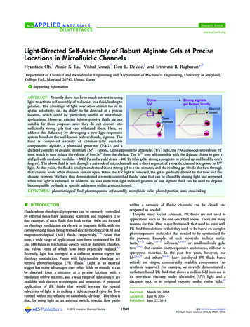
Research ArticleACS Applied Materials & InterfacesFigure 3. Rheology of PR fluids before and after exposure to UV light. Data from dynamic rheology for the elastic modulus G′ and the viscousmodulus G″ as functions of frequency ω are shown in (a) and (b) for a sample of 2.5 wt % alginate, 40 mM Sr-EGTA, and 30 mM PAG-CD. BeforeUV, the sample is a thin, viscous liquid (Photo A). After UV, the sample is a strong gel that can be lifted by one’s fingers (Photo B). In (c) and (d),data from steady-shear rheology for the viscosity as a function of shear-stress are shown. Data before UV are represented as unfilled circles while thatafter UV is shown by filled circles. Before UV, all samples exhibit Newtonian behavior, i.e., a constant, low viscosity. After UV, all samples display ayield-stress, which is the shear-stress at which the viscosity rapidly plummets from a near-infinite value. In (c), the Sr-EGTA concentration is variedwhile the alginate is held constant at 2.5 wt % and the PAG-CD at 30 mM. In (d), the PAG-CD concentration is varied while the alginate is again at2.5 wt % and the Sr-EGTA is at 40 mM.to control the infusion of fluids into the chip. Optical detection wasdone by a fluorescence microscope (Olympus MVX10 Macroview) at2 magnification.milled channel substrate and the cover piece. The microchannels werefabricated by mechanical milling using an end mill on a CNC millingmachine. Holes for the needle interface were drilled into the substrateplate using a 650 μm drill bit. The machined PMMA plate wassequentially cleaned by DI water and isopropyl alcohol to remove themilling debris, followed by a 24 h degassing step in a 40 C vacuumoven to remove the residual solvents. After vacuum drying, both theprocessed PMMA and a raw PMMA chip were oxidized by 8 min ofexposure to UV light in the presence of ozone. The oxidized PMMAwafers were immediately mated together and thermally bonded at 85 C in a hot press under a pressure of 3.45 MPa for 15 min. The worldto-chip interfaces were established by inserting hypodermic stainlesssteel needles into the 650 μm mating holes, with an additional 30 minof annealing at 85 C to release the residual stresses from the fittingprocess. The needle ports on the PMMA chip were connected tosyringes with Teflon tubing (I.D. 650 μm). Two different chips wereprepared to test different aspects pertaining to the PR fluids. The chipfor fluidic valve studies had several channels, each with a rectangularcross section (200 μm height and 300 μm width). The chip for sitespecific deposition studies had a single channel with a rectangular crosssection (200 μm height and 350 μm width) and this also had threewells (600 μm depth and 500 μm length) separated by 500 μm.Precision syringe pumps (PHD 2000, Harvard Apparatus) were used RESULTS AND DISCUSSIONThe PR fluids described here have three major components:linear alginate chains as a matrix for a 3-D network, Sr-EGTA asa source of divalent ions (Sr2 ) that can cross-link the alginatechains, and the PAG-CD complex as a phototrigger. The role ofeach component in our scheme is shown in Figure 2. Alginate isa copolymer of α-L-guluronate (G) and β-D-mannuronate (M)units.41,42 The G-blocks on two chains provide chelating sitesto divalent cations, resulting in “egg-box” junctions between thechains.42,54,55 The higher the ratio of G to M units, the morethe cross-links and the stronger the gel. In this study, thealginate used has a relatively high G content ( 51%),28 whichfacilitates the development of a strong gel.As a source of divalent cations, we used the Sr-EGTA chelate.Sr-EGTA is highly soluble in water and gives a clear solutionwhen mixed with alginate. Previously, nanoparticles of CaCO3have been used as a source of divalent cations for alginate17532DOI: 10.1021/acsami.6b03826ACS Appl. Mater. Interfaces 2016, 8, 17529 17538
Research ArticleACS Applied Materials & Interfacesprotonation capability of its moieties (four acetate groups andtwo nitrogen atoms) at the chelating site. Indeed, the chelatingefficiency of EGTA toward Sr2 ions drops sharply around a pHof 7.5, which implies a surge of free Sr2 just below this pH, asshown in the Supporting Information (SI), Figure S1.59,60 Notethat this plot of %released Sr2 vs pH has an inverse sigmoidalshape, indicating a cooperative process. This implies a switchlike response, i.e., a small drop in pH around the threshold pHof 7.5 causes a rapid and appreciable release of free Sr2 into thesolution.We then combined Sr-EGTA (40 mM) with alginate (2.5 wt%) and studied gelation of this mixture in response to pHwithout using light (Figure S2, SI). As an acid source, Dglucono-δ-lactone (GdL) was added. When GdL is dissolved inwater, it is gradually hydrolyzed and decreases the pH of thesolution.61,62 To visualize the pH change, 0.05 mM of phenolred was added. Solutions at various GdL concentrations are allinitially nonviscous and exhibit a dark pink color. Thereafter,the color and viscosity change depending on the concentrationof GdL. The photos in Figure S2 were acquired 5 h after addingGdL, which is enough time for the complete hydrolysis of GdL.Sample vials are shown inverted to visually indicate the sol togel transition.63 The sample at pH 8.0 (10 mM GdL) is pink incolor and is a low-viscosity sol. On the other hand, when thesample pH drops below 7.0 (60 and 80 mM GdL), the colorturns yellow (due to the colorimetric response of phenol red)and the samples hold their weight in the inverted vials,indicating that they are gels. Thus, the sol gel transition occursaround a pH 7.5, which is to be expected since this is thethreshold pH in Figure S1, below which free Sr2 ions areFigure 4. Rate of UV-induced gelation. A quiescent sample of 2.5 wt %alginate, 40 mM Sr-EGTA, 60 mM PAG-CD, and 0.05 mM phenol redis placed in the cuvette and exposed to UV from the top. As thesample gels, its color changes from pink to yellow due to the phenolred. The photos show the gel growing from top to bottom withincreasing time. The height of the gel region is marked on each photo.gelation;26 however, the particles make the sample turbid andinhomogeneous. If light is used as the trigger for gelation, itspenetration depth into such a sample will be low (due to lightscattering from the CaCO3 particles). Also, compared to Ca2 ions, Sr2 ions bind stronger to alginate chains, resulting in astronger gel.56,57 Consequently, using soluble Sr-EGTA insteadof suspended CaCO3 particles is better for PR fluids since itleads to a faster response as well as stronger PR effects. EGTAis a widely used chelating agent.58 The chelating capacity ofEGTA for divalent cations is highly pH-sensitive because of theFigure 5. Demonstration of localized flow-blocking using PR fluids. The setup has a main microchannel that branches into three side channelsmarked A, B, and C. The fluid used here is composed of 2.5 wt % alginate, 40 mM Sr-EGTA, 60 mM PAG-CD, and 0.5 mM phenol red. (a) Initially,all three channels are open and the fluid flows freely out of each. (b) The flow is stopped and a photomask is placed over the setup. (c) A specificportion of channel A (3 mm length) is exposed to UV light for 2 min. (d) When the flow is restarted, it is clear that flow through channel A isblocked. Note that a yellow gel (indicated by arrow) is formed in channel A over the region exposed to UV light. Also, note that channels B and Care still open, i.e., the flow-blocking is done locally and selectively. (e) Next, the same procedure is repeated with channel B, and as a result, flowthrough channel B is also blocked (but not through channel C). (f) Finally, the procedure is repeated with channel C, and thereby this channel isalso blocked. Scale bars in all images correspond to 3 mm. Movie 1 also shows the overall process.17533DOI: 10.1021/acsami.6b03826ACS Appl. Mater. Interfaces 2016, 8, 17529 17538
Research ArticleACS Applied Materials & InterfacesFigure 6. Deposition of payloads at specific addresses within a microchannel. Two PR fluids (composition: 2.5 wt % alginate, 40 mM Sr-EGTA, 60mM PAG-CD) are prepared with red- and green-fluorescent beads as model payloads. The microchannel is engineered with three wells, marked A,B, and C. (a) First, the fluid with red beads is passed through the channel, and UV light is irradiated for 2 min at the locations of wells A and C. (b)The channel is then flushed with water. At this stage, a gel with red beads is deposited in wells A and C. (c) Next, the fluid with green beads is passedthrough the channel and UV light is irradiated for 2 min at well B. (d) The channel is again flushed with water, whereupon green beads are localizedin a gel in well B. (e) The fluorescence micrograph confirms the site-selective deposition of red and green beads at their respective addresses. (f)Deposited green beads are shown to be released by a flow of EGTA solution through the channel. The decrease in green fluorescence reflects thedissolution of the gel in the wells due to the chelation of Sr2 ions by the EGTA.a mixture of x mM of PAG with 3 times that concentration ofm-β-CD.We now proceed to study the response to UV light of our PRfluids. The typical fluid contains 2.5 wt % alginate, 40 mM SrEGTA, and 30 mM PAG-CD complex. As shown by Photo Aof Figure 3a, this mixture is initially a thin solution that flowsfreely in the tilted Petri dish. Upon exposure to UV light for 20min, the solution is converted into a solid gel, and this gel isstrong enough that it can be lifted from the Petri dish and heldby one’s fingers (Photo B). Note that the gel is transparent andhomogeneous. Dynamic rheology was then used to quantifygelation. Figure 3 presents plots of the elastic modulus G′ andthe viscous modulus G″ as a function of the frequency ω for thesample before and after 20 min of UV irradiation. The initialdata before UV exposure (Figure 3a) represents a purelyviscous response, i.e., G″ is a strong function of ω (G″ ω1)while G′ is negligible and hence not seen on the plot.34,35 Incontrast, after 20 min of UV irradiation (Figure 3b), the sampleshows the response of an elastic gel, i.e., G′ G″ with bothmoduli being independent of ω.34,35 The gel modulus (value ofG′) is about 2000 Pa, which is among the highest reported inthe literature for PR fluids (as noted earlier, all PR fluids arebased on self-assembly, i.e., noncovalent bonds). In fact, thismodulus is comparable to that of chemically cross-linkedalginate bearing methacrylate groups, where covalent bonds areinduced between the chains.43released from the Sr-EGTA chelate. Figure S2 shows that thecolor change of phenol red can be used to visualize the sol geltransition, and we will employ this property later.The final element in our PR formulation is a PAG that can betriggered by light. As illustrated in Figure 2c, PAGs typicallydissociate under UV light to release H ions, with hydrophobicbyproducts also being formed.49,50 The byproducts are ofteninsoluble, which makes the sample turbid. This turbidity is aproblem for our current purpose since it hinders thepenetration of light into the sample, thus slowing down thegelation. To solve this problem, we incorporated a cyclodextrin(CD) into our sample. CDs are molecules with hydrophobiccavities that can sequester hydrophobic species,64,65 such as thebyproducts of PAG dissociation. While many types of CDs areavailable, we chose a methylated β-CD (m-β-CD) due to itshigh water solubility ( 300 mM at 25 C).65 The structure ofthis molecule is shown in Figure S3, and this figure alsoconceptualizes how the CD captures hydrophobic moieties.Various molar ratios of m-β-CD to the PAG used here(diphenyliodonium nitrate) were examined, and the sampleswith a molar ratio 3 remained transparent during the entireduration of UV exposure. The transparency indicated that therewas sufficient m-β-CD to completely sequester the hydrophobic byproducts of PAG photolysis. For this reason, wechose a m-β-CD to PAG molar ratio of 3 for our studies. Thus,in the experiments below, x mM of PAG-CD complex refers to17534DOI: 10.1021/acsami.6b03826ACS Appl. Mater. Interfaces 2016, 8, 17529 17538
Research ArticleACS Applied Materials & Interfacescm in the first 10 min, an additional 0.5 cm between 10 and 20min, and a further 0.3 cm between 20 and 30 min. The reasonfor this is that the UV light is being directed from the top andits intensity is attenuated as the path length increases. It isimportant to note that the above response is relatively fastcompared to previous PR fluids. Also, PR fluids are typicallystirred while being irradiated, which speeds up the response;here, quick gelation is achieved even with the sample in aquiescent state. Overall, it is noteworthy that the current fluidcan be converted within 10 min by UV light into a strong gelmore than 1 cm thick (i.e., a volume 1 mL).Having created PR fluids that quickly transform into stronggels, we proceed to test their flow-blocking ability inmicrochannels. The fluid we used is composed of 2.5 wt %alginate, 40 mM Sr-EGTA, 60 mM PAG-CD, and with 0.5 mMphenol red added for colorimetric observations. This fluid wassent at a flow rate of 5 μL/min through a microchannel thatbranches into three side channels (Figure 5). Each channel hasa rectangular cross section of 200 μm height and 300 μm width.Initially, all channels are open, and the fluid flows out of thethree outlets at the end of each branch (Figure 5a). Next, westopped the flow and placed a photomask to expose a specificregion (3 mm long) of Channel A to UV light (Figure 5b,c).After 2 min of UV irradiation, the flow was started again. Asshown by Figure 5d, flow through Channel A is now blockeddue to the formation of a stong alginate gel in the exposedregion. The gel again has a yellow color, as seen earlier inFigures 4 and S2. Note that Channels B and C are still open atthis stage. We then repeat the above procedure with Channel Band show that this can be selectively blocked as well (Figure5e). Lastly, we repeat the same for Channel C (Figure 5f). Amovie showing selective closure of a channel is also provided aspart of the SI (Movie 1). Note that the channel remains closedfor at least 2 h after the light is removed. However, this closureis not permanent. As time progresses, the gel is graduallydissolved by the flow, causing the channel to eventually reopen.We have thus demonstrated a fluidic valve that can be closed byshining light and reopened when the light is removed.We now briefly discuss the mechanism behind flow-blocking.To a first approximation, flow-blocking req
Light-Directed Self-Assembly of Robust Alginate Gels at Precise Locations in Microfluidic Channels Hyuntaek Oh,† Annie Xi Lu,† Vishal Javvaji,† Don L. DeVoe,‡ and Srinivasa R. Raghavan*,† †Department of Chemical and Biomolecular Engineering and ‡Department of Mechanical Engineering, University of Maryland, College Park, Maryland 20742, United States