Transcription
Neuman, M. R. “Biopotential Electrodes.”The Biomedical Engineering Handbook: Second Edition.Ed. Joseph D. BronzinoBoca Raton: CRC Press LLC, 2000
48Biopotential ElectrodesMichael R. NeumanJoint Program in BiomedicalEngineering, The Universityof Memphis and Universityof Tennessee, Memphis48.148.248.3Sensing Bioelectric SignalsElectrical CharacteristicsPractical Electrodes for Biomedical MeasurementsBody-Surface Biopotential Electrodes Intracavity andIntratissue Electrodes Microelectrodes ElectrodesFabricated Using Microelectronic Technology48.4Biomedical ApplicationsBiologic systems frequently have electric activity associated with them. This activity can be a constantdc electric field, a constant flux of charge-carrying particles or current, or a time-varying electric fieldor current associated with some time-dependent biologic or biochemical phenomenon. Bioelectric phenomena are associated with the distribution of ions or charged molecules in a biologic structure and thechanges in this distribution resulting from specific processes. These changes can occur as a result ofbiochemical reactions, or they can emanate from phenomena that alter local anatomy.One can find bioelectric phenomena associated with just about every organ system in the body.Nevertheless, a large proportion of these signals are associated with phenomena that are at the presenttime not especially useful in clinical medicine and represent time-invariant, low-level signals that are noteasily measured in practice. There are, however, several signals that are of diagnostic significance or thatprovide a means of electronic assessment to aid in understanding biologic systems. These signals, theirusual abbreviations, and the systems they measure are listed in Table 48.1. Of these, the most familiar isthe electrocardiogram, a signal derived from the electric activity of the heart. This signal is widely usedin diagnosing disturbances in cardiac rhythm, signal conduction through the heart, and damage due tocardiac ischemia and infarction. The electromyogram is used for diagnosing neuromuscular diseases,and the electroencephalogram is important in identifying brain dysfunction and evaluating sleep. Theother signals listed in Table 48.1 are currently of lesser diagnostic significance but are, nevertheless, usedfor studies of the associated organ systems.Although Table 48.1 and the above discussion are concerned with bioelectric phenomena in animalsand these techniques are used primarily in studying mammals, bioelectric signals also arise from plants[1]. These signals are generally steady-state or slowly changing, as opposed to the time-varying signalslisted in Table 48.1. An extensive literature exists on the origins of bioelectric signals, and the interestedreviewer is referred to the text by Plonsey and Barr for a general overview of this area [2].48.1 Sensing Bioelectric SignalsThe mechanism of electric conductivity in the body involves ions as charge carriers. Thus, picking upbioelectric signals involves interacting with these ionic charge carriers and transducing ionic currentsinto electric currents required by wires and electronic instrumentation. This transducing function iscarried out by electrodes that consist of electrical conductors in contact with the aqueous ionic solutions 2000 by CRC Press LLC
TABLE 48.1 Bioelectric Signals Sensed by Biopotential Electrodesand Their SourcesBioelectric SignalAbbreviationBiologic SourceECG—EMGEEGEOGERG—EGGGSRHeart—as seen from body surfaceHeart—as seen from withinMuscleBrainEye dipole fieldEye retinaNerve or muscleStomachSkinElectrocardiogramCardiac rooptigramElectroretinogramAction potentialElectrogastrogramGalvanic skin reflexof the body. The interaction between electrons in the electrodes and ions in the body can greatly affectthe performance of these sensors and requires that specific considerations be made in their application.At the interface between an electrode and an ionic solution redox (oxidation-reduction), reactionsneed to occur for a charge to be transferred between the electrode and the solution. These reactions canbe represented in general by the following equations:C 1C n ne (48.1)Am 1A me (48.2)where n is the valence of cation material C, and m is the valence of anion material, A. For most electrodesystems, the cations in solution and the metal of the electrodes are the same, so the atoms C are oxidizedwhen they give up electrons and go into solution as positively charged ions. These ions are reduced whenthe process occurs in the reverse direction. In the case of the anion reaction, Eq. (48.2), the directionsfor oxidation and reduction are reversed. For best operation of the electrodes, these two reactions shouldbe reversible, that is, it should be just as easy for them to occur in one direction as the other.The interaction between a metal in contact with a solution of its ions produces a local change in theconcentration of the ions in solution near the metal surface. This causes charge neutrality not to bemaintained in this region, causing the electrolyte surrounding the metal to be at a different electricalpotential from the rest of the solution. Thus, a potential difference known as the half-cell potential isestablished between the metal and the bulk of the electrolyte. It is found that different characteristicpotentials occur for different materials, and some of these potentials are summarized in Table 48.2. Thesehalf-cell potentials can be important when using electrodes for low frequency or dc measurements.The relationship between electric potential and ionic concentrations or, more precisely, ionic activitiesis frequently considered in electrochemistry. Most commonly two ionic solutions of different activity areseparated by an ion-selective semipermeable membrane that allows one type of ion to pass freely throughTABLE 48.2 Half-cell Potentials for Materialsand Reactions Encountered in Biopotential Measurement 2000 by CRC Press LLCMetal and ReactionHalf-cell Potential, VAl Al3 3e–Ni Ni2 2e–H2 2H 2e–Ag Cl – AgCl e–Ag Ag e–Au Au e––1.706–0.2300.000 (by definition) 0.223 0.799 1.680
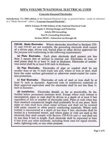
the membrane. It can be shown that an electric potential E will exist between the solutions on either sideof the membrane, based upon the relative activity of the permeable ions in each of these solutions. Thisrelationship is known as the Nernst equationE RT a1 ln nF a2 (48.3)where a1 and a2 are the activities of the ions on either side of the membrane, R is the universal gasconstant, T is the absolute temperature, n is the valence of the ions, and F is the Faraday constant. Moredetail on this relationship can be found in Chapter 49.When no electric current flows between an electrode and the solution of its ions or across an ionpermeable membrane, the potential observed should be the half-cell potential or the Nernst potential,respectively. If, however, there is a current, these potentials can be altered. The difference between thepotential at zero current and the measured potentials while current is passing is known as the over voltageand is the result of an alteration in the charge distribution in the solution in contact with the electrodesor the ion-selective membrane. This effect is known as polarization and can result in diminished electrodeperformance, especially under conditions of motion. There are three basic components to the polarizationover potential: the ohmic, the concentration, and the activation over potentials. Of these, the activationover potential is of greatest concern in bioelectric measurements. More details on these over potentialscan be found in electrochemistry or biomedical instrumentation texts [4].Perfectly polarizable electrodes pass a current between the electrode and the electrolytic solution bychanging the charge distribution within the solution near the electrode. Thus, no actual current crossesthe electrode-electrolyte interface. Nonpolarized electrodes, however, allow the current to pass freelyacross the electrode-electrolyte interface without changing the charge distribution in the electrolyticsolution adjacent to the electrode. Although these types of electrodes can be described theoretically,neither can be fabricated in practice. It is possible, however, to come up with electrode structures thatclosely approximate their characteristics.Electrodes made from noble metals such as platinum are often highly polarizable. A charge distributiondifferent from that of the bulk electrolytic solution is found in the solution close to the electrode surface.Such a distribution can create serious limitations when movement is present and the measurementinvolves low frequency or even dc signals. If the electrode moves with respect to the electrolytic solution,the charge distribution in the solution adjacent to the electrode surface will change, and this will inducea voltage change in the electrode that will appear as motion artifact in the measurement. Thus, for mostbiomedical measurements, nonpolarizable electrodes are preferred to those that are polarizable.The silver–silver chloride electrode is one that has characteristics similar to a perfectly nonpolarizableelectrode and is practical for use in many biomedical applications. The electrode (Fig. 48.1a) consists ofa silver base structure that is coated with a layer of the ionic compound silver chloride. Some of the silverchloride when exposed to light is reduced to metallic silver, so a typical silver–silver chloride electrodehas finely divided metallic silver within a matrix of silver chloride on its surface. Since the silver chlorideis relatively insoluble in aqueous solutions, this surface remains stable. Because there is minimal polarization associated with this electrode, motion artifact is reduced compared to polarizable electrodes suchas the platinum electrode. Furthermore, due to the reduction in polarization, there is also a smaller effectof frequency on electrode impedance, especially at low frequencies.Silver–silver chloride electrodes of this type can be fabricated by starting with a silver base andelectrolytically growing the silver chloride layer on its surface [4]. Although an electrode produced inthis way can be used for most biomedical measurements, it is not a robust structure, and pieces of thesilver chloride film can be chipped away after repeated use of the structure. A structure with greatermechanical stability is the sintered silver–silver chloride electrode in Fig. 48.1b. This electrode consistsof a silver lead wire surrounded by a sintered cylinder made up of finely divided silver and silver-chloridepowder pressed together. 2000 by CRC Press LLC
FIGURE 48.1 Silver–silver electrodes for biopotential measurements: (a) metallic silver with a silver chloride surfacelayer and (b) sintered electrode structure. The lower views show the electrodes in cross-section.In addition to its nonpolarizable behavior, the silver–silver chloride electrode exhibits less electricalnoise than the equivalent polarizable electrodes. This is especially true at low frequencies, and so silver–silver chloride electrodes are recommended for measurements involving very low voltages for signalsthat are made up primarily of low frequencies. A more detailed description of silver–silver chlorideelectrodes and methods to fabricate these devices can be found in Janz and Ives [5] and biomedicalinstrumentation textbooks [4].48.2 Electric CharacteristicsThe electric characteristics of biopotential electrodes are generally nonlinear and a function of the currentdensity at their surface. Thus, having the devices represented by linear models requires that they be operatedat low potentials and currents. Under these idealized conditions, electrodes can be represented by anequivalent circuit of the form shown in Fig. 48.2. In this circuit Rd and Cd are components that representthe impedance associated with the electrode-electrolyte interface and polarization at this interface. Rs is theseries resistance associated with interfacial effects and the resistance of the electrode materials themselves.FIGURE 48.2 2000 by CRC Press LLCThe equivalent circuit for a biopotential electrode.
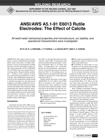
FIGURE 48.3 An example of biopotential electrode impedance as a function of frequency. Characteristic frequencieswill be somewhat different for electrode different geometries and materials.TABLE 48.3The Effect of Electrode Properties on Electrode ImpedancePropertySurface areaPolarizationSurface roughnessRadius of curvatureSurface contaminationChange in PropertyChanges in Electrode Impedance At low frequencies The battery Ehc represents the half-cell potential described above. It is seen that the impedance of thiselectrode will be frequency dependent, as illustrated in Fig. 48.3. At low frequencies the impedance isdominated by the series combination of Rs and Rd , whereas at higher frequencies Cd bypasses the effect ofRd so that the impedance is now close to Rs . Thus, by measuring the impedance of an electrode at high andlow frequencies, it is possible to determine the component values for the equivalent circuit for that electrode.The electrical characteristics of electrodes are affected by many physical properties of these electrodes.Table 48.3 lists some of the more common physical properties of electrodes and qualitatively indicateshow these can affect electrode impedance.48.3 Practical Electrodes for Biomedical MeasurementsMany different forms of electrodes have been developed for different types of biomedical measurements.To describe each of these would go beyond the constraints of this article, but some of the more commonlyused electrodes are presented in this section. The reader is referred to the monograph by Geddes formore details and a wider selection of practical electrodes [6].Body-Surface Biopotential ElectrodesThis category includes electrodes that can be placed on the body surface for recording bioelectric signals.The integrity of the skin is not compromised when these electrodes are applied, and they can be usedfor short-term diagnostic recording such as taking a clinical electrocardiogram or long-term chronicrecording such as occurs in cardiac monitoring. 2000 by CRC Press LLC
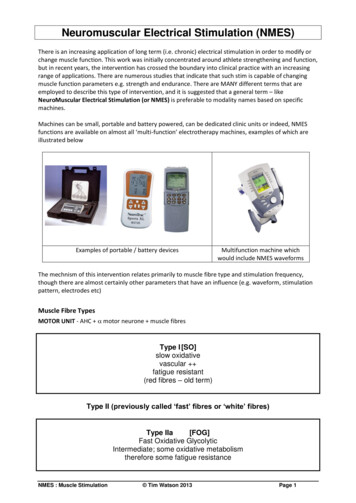
Metal Plate ElectrodesThe basic metal plate electrode consists of a metallic conductor in contact with the skin with a thin layerof an electrolyte gel between the metal and the skin to establish this contact. Examples of metal plateelectrodes are seen in Fig. 48.4a. Metals commonly used for this type of electrode include German silver(a nickel-silver alloy), silver, gold, and platinum. Sometimes these electrodes are made of a foil of themetal so as to be flexible, and sometimes they are produced in the form of a suction electrode (Fig. 48.4b)to make it easier to attach the electrode to the skin to make a measurement and then move it to anotherpoint to repeat the measurement. These types of electrodes are used primarily for diagnostic recordingsof biopotentials such as the electrocardiogram or the electroencephalogram. Metal disk electrodes witha gold surface in a conical shape such as shown in Fig. 48.4c are frequently used for EEG recordings. Theapex of the cone is open so that electrolyte gel or paste can be introduced to both make good contactbetween the electrode and the head and to allow this contact medium to be replaced should it dry outduring its use.FIGURE 48.4 Examples of different skin electrodes: (a) metal plate electrodes, (b) suction electrode for ECG,(c) metal cup EEG electrode, (d) recessed electrode, (e) disposable electrode with electrolyte-impregnated sponge(shown in cross-section), ( f ) disposable hydrogel electrode (shown in cross-section), (g) thin-film electrode for usewith neonates (shown in cross-section), (h) carbon-filled elastomer dry electrode. 2000 by CRC Press LLC
FIGURE 48.4 (continued) 2000 by CRC Press LLC
Electrodes for Chronic Patient MonitoringLong-term monitoring of biopotentials such as the electrocardiogram as performed by cardiac monitorsplaces special constraints on the electrodes used to pick up the signals. These electrodes must have astable interface between them and the body, and frequently nonpolarizable electrodes are, therefore, thebest for this application. Mechanical stability of the interface between the electrode and the skin can helpto reduce motion artifact, and so there are various approaches to reduce interfacial motion between theelectrode and the coupling electrolyte or the skin. Figure 48.4d is an example of one approach to reducemotion artifact by recessing the electrode in a cup of electrolytic fluid or gel. The cup is then securelyfastened to the skin surface using a double-sided adhesive ring. Movement of the skin with respect tothe electrode may affect the electrolyte near the skin-electrolyte interface, but the electrode-electrolyteinterface can be several millimeters away from this location, since it is recessed in the cup. The fluidmovement is unlikely to affect the recessed electrode-electrolyte interface as compared to what wouldhappen if the electrode was separated from the skin by just a thin layer of electrolyte.The advantages of the recessed electrode can be realized in a simpler design that lends itself to massproduction through automation. This results in low per-unit cost so that these electrodes can be considered disposable. Figure 48.4e illustrates such an electrode in cross section. The electrolyte layer nowconsists of an open-celled sponge saturated with a thickened (high-viscosity) electrolytic solution. Thesponge serves the same function as the recess in the cup electrodes and is coupled directly to a silver–silverchloride electrode. Frequently, the electrode itself is attached to a clothing snap through an insulatingadhesive disk that holds the structure against the skin. This snap serves as the point of connection to alead wire. Many commercial versions of these electrodes in various sizes are available, including electrodeswith a silver–silver chloride interface or ones that use metallic silver as the electrode material.A recently developed modification of this basic monitoring electrode structure is shown in Fig. 48.4f.In this case the metal electrode is a silver foil with a surface coating of silver chloride. The foil gives theelectrode increased flexibility to fit more closely over body contours. Instead of using the sponge, ahydrogel film (really a sponge on a microscopic level) saturated with an electrolytic solution and formedfrom materials that are very sticky is placed over the electrode surface. The opposite surface of the hydrogellayer can be attached directly to the skin, and since it is very sticky, no additional adhesive is needed.The mobility and concentration of ions in the hydrogel layer is generally lower than for the electrolyticsolution used in the sponge or the cup. This results in an electrode that has a higher source impedanceas compared to these other structures. An important advantage of this structure is its ability to have theelectrolyte stick directly on the skin. This greatly reduces interfacial motion between the skin surface andthe electrolyte, and hence there is a smaller amount of motion artifact in the signal. This type of hydrogelelectrode is, therefore, especially valuable in monitoring patients who move a great deal or during exercise.Thin-film flexible electrodes such as shown in Fig. 48.4g have been used for monitoring neonates. Theyare basically the same as the metal plate electrodes; only the thickness of the metal in this case is less thana micrometer. These metal films need to be supported on a flexible plastic substrate such as polyester orpolyimide. The advantage of using only a thin metal layer for the electrode lies in the fact that theseelectrodes will then become x-ray transparent. This is especially important in infants where repeatedplacement and removal of electrodes, so that x-rays may be taken, can cause substantial skin irritation.Electrodes that do not use artificially applied electrolyte solutions or gels and, therefore, are oftenreferred to as dry electrodes have been used in some monitoring applications. These sensors as illustratedin Fig. 48.4h can be placed on the skin and held in position by an elastic band or tape. They are madeup of a graphite or metal-filled polymer such as silicone. The conducting particles are ground into a finepowder, and this is added to the silicone elastomer before it cures so to produce a conductive materialwith physical properties similar to that of the elastomer. When held against the skin surface, theseelectrodes establish contact with the skin without the need for an electrolytic fluid or gel. In actualitysuch a layer is formed by sweat under the electrode surface. For this reason these electrodes tend toperform better after they have been left in place for an hour or two so that this layer forms. Someinvestigators have found that placing a drop of physiologic saline solution on the skin before applying 2000 by CRC Press LLC
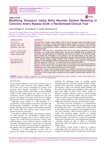
the electrode accelerates this process. This type of electrode has found wide application in home infantcardiorespiratory monitoring because of the ease with which it can be applied by untrained caregivers.Intracavitary and Intratissue ElectrodesElectrodes can be placed within the body for biopotential measurements. These electrodes are generallysmaller than skin surface electrodes and do not require special electrolytic coupling fluid, since naturalbody fluids serve this function. There are many different designs for these internal electrodes, and onlya few examples are given in the following paragraphs. Basically these electrodes can be classified as needleelectrodes, which can be used to penetrate the skin and tissue to reach the point where the measurementis to be made, or they are electrodes that can be placed in a natural cavity or surgically produced cavityin tissue. Figure 48.5 illustrates some of these internal electrodes.A catheter tip or probe electrode is placed in a naturally occurring cavity in the body such as in thegastrointestinal system. A metal tip or segment on a catheter makes up the electrode. The catheter or, inthe case where there is no hollow lumen, probe, is inserted into the cavity so that the metal electrodeFIGURE 48.5 Examples of different internal electrodes: (a) catheter or probe electrode, (b) needle electrode,(c) coaxial needle electrode, (d) coiled wire electrode. (Reprinted with permission from Webster JG (ed). 1992.Medical Instrumentation: Application and Design, Houghton Mifflin, Boston.) 2000 by CRC Press LLC
makes contact with the tissue. A lead wire down the lumen of the catheter or down the center of theprobe connects the electrode to the external circuitry.The basic needle electrode shown in Fig. 48.5b consists of a solid needle, usually made of stainlesssteel, with a sharp point. An insulating material coats the shank of the needle up to a millimeter or twoof the tip so that the very tip of the needle remains exposed. When this structure is placed in tissue suchas skeletal muscle, electrical signals can be picked up by the exposed tip. One can also make needleelectrodes by running one or more insulated wires down the lumen of a standard hypodermic needle.The electrode as shown in Fig. 48.5c is shielded by the metal of the needle and can be used to pick upvery localized signals in tissue.Fine wires can also be introduced into tissue using a hypodermic needle, which is then withdrawn.This wire can remain in tissue for acute or chronic measurements. Caldwell and Reswick have used finecoiled wire electrodes in skeletal muscle for several years without adverse effects [7].MicroelectrodesThe electrodes described in the previous paragraphs have been applied to studying bioelectric signals atthe organism, organ, or tissue level but not at the cellular level. To study the electric behavior of cells,electrodes that are themselves smaller than the cells being studied need to be used. Three types ofelectrodes have been described for this purpose: etched metal electrodes, micropipette electrodes, andmetal-film-coated micropipette electrodes. The metal microelectrode is essentially a subminiature versionof the needle electrode described in the previous section (Fig. 48.6a). In this case, a strong metal suchas tungsten is used. One end of this wire is etched electrolytically to give tip diameters on the order of afew micrometers. The structure is insulated up to its tip, and it can be passed through the membrane ofa cell to contact the cytosol. The advantage of these electrodes is that they are both small and robust andFIGURE 48.6 Microelectrodes: (a) metal, (b) micropipette, (c) thin metal film on micropipette. (Reprinted withpermission from Webster JC (ed). 1992. Medical Instrumentation: Application and Design, Houghton Mifflin, Boston.) 2000 by CRC Press LLC
can be used for neurophysiologic studies. Their principal disadvantage is the difficulty encountered intheir fabrication and their high source impedance.The second and most frequently used type of microelectrode is the glass micropipette. This structure,as illustrated in Fig. 48.6b consists of a fine glass capillary drawn to a very narrow point and filled withan electrolytic solution. The point can be as narrow as a fraction of a micrometer, and the dimensionsof this electrode are strongly dependent on the skill of the individual drawing the tip. The electrolyticsolution in the lumen serves as the contact between the interior of the cell through which the tip hasbeen impaled and a larger conventional electrode located in the shank of the pipette. These electrodesalso suffer from high source impedances and fabrication difficulty.A combined form of these two types of electrodes can be achieved by depositing a metal film over theoutside surface of a glass micropipette as shown in Fig. 48.6c. In this case, the strength and smallerdimensions of the micropipette can be used to support films of various metals that are insulated by anadditional film up to a point very close to the actual tip of the electrode structure. These electrodes havebeen manufactured in quantity and made available as commercial products. Since they combine thefeatures of both the metal and the micropipette electrodes, they also suffer from many of the samelimitations. They do, however, have the advantage of flexibility due to the capability of being able tomake films of different metals on the micropipette surface without having to worry about the strengthof the metal, as would be the case if the metal were used alone.Electrodes Fabricated Using Microelectronic TechnologyModern microelectronic technology can be used to fabricate many different types of electrodes for specificbiomedical applications. For example, dry electrodes with high source resistances or microelectrodes withsimilar characteristics can be improved by incorporating a microelectronic amplifier for impedance conversion right on the electrode itself. In the case of the conventional-sized electrodes, a metal disk 5–10 mmin diameter can have a high input impedance microelectronic amplifier configured as a follower integratedinto the back of the electrode so that localized processing of the high source impedance signal can produceone of lower, more practical impedance for signal transmission [8]. Single- and multiple-element electrodescan be made from thin-film or silicon technology. Mastrototaro and colleagues have demonstrated probesfor measuring intramyocardial potentials using thin, patterned gold films on polyimide or oxidised molybdenum substrates [9]. When electrodes are made from pieces of micromachined silicon, it is possible tointegrate an amplifier directly into the electrode [10]. Multichannel amplifiers or multiplexers can be usedwith multiple electrodes on the same probe. Electrodes for contact with individual nerve fibers can befabricated using micromachined holes in a silicon chip that are just big enough to pass a single growingaxon. Electrical contacts on the sides of these holes can then be used to pick up electrical activity from thesenerves [11]. These examples are just a few of the many possibilities that can be realized using microelectronicsand three-dimensional micromachining technology to fabricate specialized electrodes.48.4 Biomedical ApplicationsElectrodes can be used to perform a wide variety of measurements of bioelectric signals. An extensivereview of this would be beyond the scope of this chapter, but some typical examples of applications arehighlighted in Table 48.4. The most popular application for biopotential electrodes is in obtaining theelectrocardiogram for diagnostic and patient-monitoring applications. A substantial commercial marketexists for various types of electrocardiographic electrodes, and many of the forms described in theprevious section are available commercially. Other electrodes for measuring bioelectric potentials forapplication in diagnostic medicine are indicated in Table 48.4. Research applications of biopotentialelectrodes are highly varied and specific for individual studies. Although a few examples are given inTable 48.4, the field is far too broad to be completely covered here.Biopotential electrodes are one of the most common biomedical sensors used in clinical medicine.Although their basic principle of operation is the same for most applications, they take on many forms 2000 by CRC Press LLC
TABLE 48.4Examples of Applications of Biopotential ElectrodesApplicationBiopotentialCardiac monitoringECGInfant cardiopulmonary monitoringECG impedanceSleep encephalographyEEGDiagnostic muscle activityCardiac electrogramsImplanted telemetry of biopotentialsEMGElectrogramECGEMGEOGEye movementType of ElectrodeAg/AgCl with spongeAg/AgCl with hydrogelAg/AgCl with
involves low frequency or even dc signals. If the electrode moves with respect to the electrolytic solution, the charge distribution in the solution adjacent to the electrode surface will change, and this will induce a voltage change in the electrode that will appear as motion artifact in the measurement. Thus, for most