Transcription
Introduction toSS7 SignalingThis tutorial provides an overview of Signaling SystemNo. 7 (SS7) network architecture and protocolsSS7 is a set of telephony signaling protocols that areused to set up most of the world’s public switched telephone network (PSTN) telephone calls. SS7 primarilysets up and tears down telephone calls, but other usesinclude number translation, prepaid billing mechanisms, local number portability, short message service(SMS), and a variety of mass-market services.
CopyrightCopyright 2012, Patton Electronics Company. All rights reserved.Printed in the USA.2
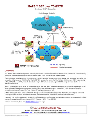
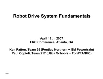
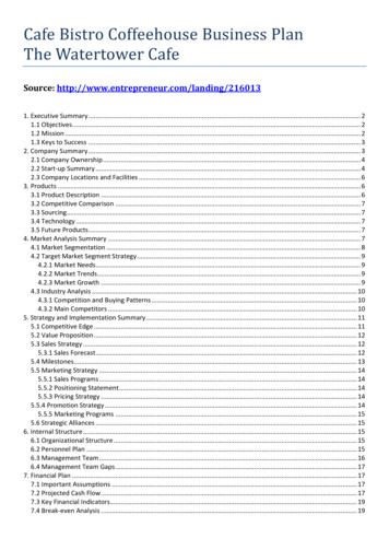
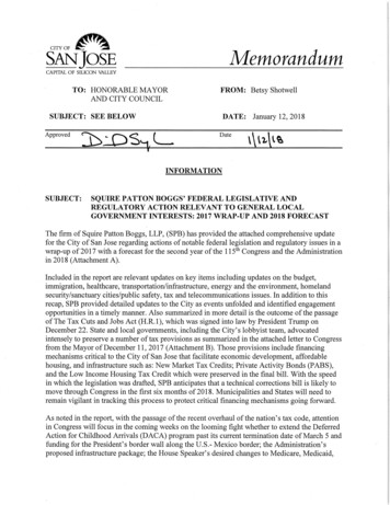
SS7: Common Channel Signaling SystemNo. 7 (SS7 or C7)Figure 1. CAS: ESF, SF, RBS, MFR2A worldwide standard for telecommunications definedby the International Telecommunication Union (ITU)Telecommunication Standardization Sector (ITU-T).The SS7 standard defines the procedures and protocol by which network elements in the public switchedtelephone network (PSTN) exchange information overa digital signaling network to enable wireless (cellular)and wireline call setup, routing, and control.Variants of SS7American National Standards Institute (ANSI) and BellCommunications Research (Telcordia Technologies)standards used in North America and the EuropeanTelecommunications Standards Institute (ETSI) standard used in Europe.and billing. The two forms of signaling that you aremost familiar with used by Patton products are: Channel Associated Signaling (CAS) RBS orMFR2 are examples of CAS signaling (seeFigure 1). Common Channel Signaling (CCS) ISDN-PRI(see Figure 2).Figure 2. CCS: PRI-ISDNThe SS7 network and protocol are used for: Basic call setup, management, and tear down Wireless services such as personal communications services (PCS), wireless roaming, andmobile subscriber authentication Local number portability (LNP) Toll-free (800/888) and toll (900) wireline services Enhanced call features such as call forwarding,calling party name/number display, and threeway calling Efficient and secure worldwide telecommunications SMS (Short Message Service)SignalingEverything in the telecommunications network isbased on signaling—call setup, connection, teardown,You already know ISDNIntegrated Services Digital Network—Primary RateInterface (ISDN-PRI) divides digital transport servicesinto bearer channels (B-channels) for voice and datatransmission and data channels (D-channels) for signaling data.In North America T1-PRI employs 24 channels(23B 1D at 64 Kbps per PCM channel) with an aggregate bandwidth of 1.536 Mbps. In Europe E1-PRIemploys 32 channels (30B 2D at 64 Kbps per PCMchannel) with an aggregate bandwidth of 2.048 Mbps.However the principal disadvantage of ISDN-PRI is itsuse of Associated Signaling mode, which only workswith directly trunked switches.3
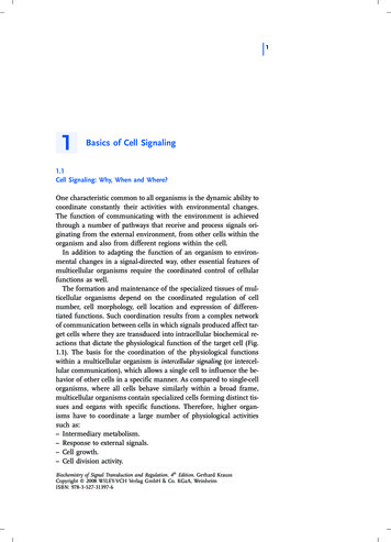
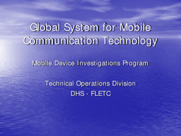
SS7 like ISDN uses a form of CCSSignaling ModesWhile similar to ISDN-PRI, Signaling System NumberSeven (SS7) uses different messaging for call setupand teardown. SS7 lets any SS7-enabled node to talkto any other, regardless of whether they have directtrunk connections between them. Associated Signaling—Uses one dedicatedpath between switches as the signaling link.Examples: ISDN-PRI and E1-CAS. Non-Associated Signaling—Uses separate logical paths and multiple nodes. Quasi-Associated Signaling—Uses a minimalnumber of nodes (preferred for SS7, causesless delay).The preferred mode of signaling for SS7 networks isQuasi-Associated, whereas ISDN-PRI uses theAssociated Signaling mode.Signaling Links (Commonchannel signaling)SS7 messages are 56 or 64 kbps bidirectional channels called (signaling links) exchanged between network elements. Signaling occurs out-of-band on dedicated channels rather than in-band on voice channels.Associated SignalingWith this type of signaling, the signaling link directlyparallels associated voice trunks. Thus, dedicatedlinks must be provisioned between every interconnected switch. (See Figure 1-3.)Figure 1-3. Associated SignalingSS7 is a form of common channel signaling, that provides intelligence to the network, and allows quickercall setup and teardown—saving time and money.Compared to in-band signaling, out-of-band signaling provides: Faster call setup times (compared to in-band signaling using multi-frequency (MF) signaling tones) More efficient use of voice circuits Support for Intelligent Network (IN) serviceswhich require signaling to network elements without voice trunks (e.g., database systems) Improved control over fraudulent network usage Lowering network operating costs by reducingSS7 links.Non-Associated SignalingWith this type of signaling, voice/data and signalingare carried on separate, logical paths. Multiple nodesin the signaling path to the final destination can cause4
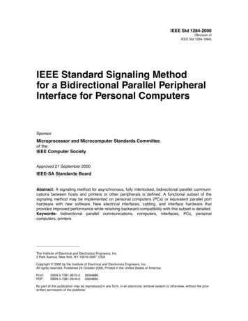
delays. Although used in the SS7 network, it is not preferred. (See Figure 1-4.)ty to read a Point Code and determine if the messageis for that node and the ability to route SS7 messagesto another SP.Figure 1-4. Non-Associated SignalingEach signaling point in the SS7 network is uniquelyidentified by a numeric point code. Point codes are carried in signaling messages exchanged between signaling points to identify the source and destination of eachmessage. Each signaling point uses a routing table toselect the appropriate signaling path for each message.There are three kinds of signaling points in the SS7network (see Figure 6): SSP (Service Switching Point or SignalSwitching Point)Quasi-Associated Signaling STP (Signal Transfer Point)This type of signaling employs a minimal number ofnodes, thus minimizing delays. Quasi-associated signaling is the preferred signaling mode for SS7. (SeeFigure 1-5.) SCP (Service Control Point)Figure 1-6. SS7 Signaling PointsFigure 1-5. Quasi-Associated SignalingService Switching Point (SSP)Signaling PointsAll nodes in the SS7 network are called SignalingPoints (SPs). Each SP is identified by a uniqueaddress called a Point Code (PC). SPs have the abili-SSPs are switches, for example, Class 5 (local) andClass 4 (tandem) with SS7 interfaces.SSPs convert global title digits (i.e. a dialed number)from a subscriber line to SS7 signaling messages.5
SSPs setup, manage and release voice circuitsSS7 Signaling Links:required to make a call.All SPs (signaling points) are connected using (typically) pairs of Links. Each Link type is identified with aletter as defined below:SSPs send messages using the ISDN User Part(ISUP) and Transaction Capabilities Application Part(TCAP) protocolsTo summarize, an SSP’s function is to use a global titleto determine how to connect a call using itsrouting table.Type A—Access Links (used to connectSSPs to STPs or STPs to SCPs)Signal Transfer Point (STP):An “A” (access) link connects a signaling end point (forexample, an SCP or SSP) to an STP. Only messagesoriginating from or destined to the signaling end pointare transmitted on an A link.An STP is a router and/or a gateway in the SS7 network.Messages are not originated by an STP.STPs switch SS7 messages between signaling points.If an originating SSP does not know the address of adestination SSP, the STP must provide it using GlobalTitle Translation.Gateway STPs serve as the interface into another network and they can provide protocol conversion .STPs also provide traffic and usage measurements.Service Control Point (SCP)An SCP provides application access. It is an interfaceto applications such as databases.Type B—Bridge Links (used to connectpaired STPs to other paired STPs).A “B” (bridge) link connects an STP to another STP.Typically, a quad of “B” links interconnect peer (or primary) STPs (for example, the STPs from one networkto the STPs of another network). The distinctionbetween a B link and a D link is rather arbitrary. Forthis reason, such links may be referred to as B/D links.An SCP communicates with applications using primitives. A primitive is an interface that provides accessfrom one level of a protocol to another level.The protocol used to access and interface a databaseapplication is TCAP.6
Type C—Cross Links (used to connectpaired STPs)A “C” (cross) link connects STPs performing identicalfunctions into a mated pair. A C link is used only whenan STP has no other route available to a destinationsignaling point due to link failure(s). Note that SCPsmay also be deployed in pairs to improve reliability;unlike STPs, however, mated SCPs are not interconnected by signaling links.Type D—Diagonal Links (used to connect paired STPs at one in the hierarchy to paired STPs at another level inthe hierarchy)A “D” (diagonal) link connects a secondary (local orregional) STP pair to a primary (for example, inter-network gateway) STP pair in a quad-link configuration.Secondary STPs within the same network are connected via a quad of D links. The distinction betweena B link and a D link is rather arbitrary. For this reason,such links may be referred to as B/D links.Type E—Extended Links (connectsSSPs to alternate or remote STPs forincreased resiliance and load sharing)An “E” (extended) link connects an SSP to an alternateSTP. E links provide an alternate signaling path if anSSP’s home STP cannot be reached via an A link. Elinks are not usually provisioned unless the benefit ofa marginally higher degree of reliability justifies theadded expense.Type F—Fully Associated Links (usedto connect SSPs when significant traffic flows between them)An “F” (fully associated) link connects two signalingend points (i.e., SSPs and SCPs). F links are not usually used in networks with STPs. In networks withoutSTPs, F links directly connect signaling points.7
All links use the same physical connections, typicallyDS0A—56 kbps or DS1 (T1). The letter designationallows differing congestion and recovery treatment.SS7 Protocol LayersThe SS7 protocol is designed to both facilitate thesefunctions and to maintain the network over which theyare provided. Like most modern protocols, the SS7protocol is layered.Physical Layer MTP Layer 1This defines the physical and electrical characteristicsof the signaling links of the SS7 network. Signalinglinks utilize DS–0 channels and carry raw signalingdata at a rate of 56 kbps or 64 kbps (56 kbps is themore common implementation).Data Link Layer MTPThe layer 2 portion provides link-layer functionality. Itensures that the two end points of a signaling link canreliably exchange signaling messages. It incorporatessuch capabilities as error checking, flow control, andsequence checking.Network Layer MTPThe layer 3 portion extends the functionality providedby MTP level 2 to provide network layer functionality. Itensures that messages can be delivered between signaling points across the SS7 network regardless ofwhether they are directly connected. It includes suchcapabilities as node addressing, routing, alternaterouting, and congestion control8
Signaling Connection ControlPart (SCCP)The signaling connection control part (SCCP) providestwo major functions that are lacking in the MTP. Thefirst of these is the capability to address applicationswithin a signaling point. The MTP can only receive anddeliver messages from a node as a whole; it does notdeal with software applications within a node.While MTP network-management messages and basiccall-setup messages are addressed to a node as awhole, other messages are used by separate applications (referred to as subsystems) within a node.Examples of subsystems are 800 call processing, calling-card processing, advanced intelligent network (AIN),and custom local-area signaling services (CLASS) services (e.g., repeat dialing and call return). The SCCPallows these subsystems to be addressed explicitly.Enhanced routing is called global title (GT) routing. Itkeeps SPs from having overly large routing tables thatwould be difficult to provision and maintain. A GT is adirectory number that serves as an alias for a physicalnetwork address. A physical address consists of apoint code and an application reference called a subsystem number (SSN). GT routing allows SPs to usealias addressing to save them from having to maintainoverly large physical address tables. Centralized STPsare then used to convert the GT address into a physical address; this process is called Global TitleTranslation (GTT). This provides the mapping of traditional telephony addresses (phone numbers) to SS7addresses (PC and/or SSN) for enhanced services.GTT is typically performed at STPs.ISDN User Part (ISUP)ISUP user part defines the messages and protocolused in the establishment and tear down of voice anddata calls over the public switched network (PSN), andto manage the trunk network on which they rely.Despite its name, ISUP is used for both ISDN andnon–ISDN calls. In the North American version of SS7,ISUP messages rely exclusively on MTP to transportmessages between concerned nodesDefinitionsAIN—Advanced Intelligent NetworkANSI—American National Standards InstituteCAS—Channel Associated SignalingCCS—Common Channel SignalingCLASS—Custom Local-Area Signaling ServicesDPC—Destination Point Code is used to identify themessage destination (this is key for the routing of themessage on the SS7 network)ETSI—European TelecommunicationsStandards InstituteGT—Global Title used as a directory number used asan alias for a physical network.GTT—Global Title Translation is the conversion of theGT address into a physical addressISDN—Integrated Services Digital NetworkISDN-PRI—Integrated Services Digital NetworkPrimary Rate Interface9
ISUP—ISDN User PartITU—International Telecommunication UnionITU-T—Telecommunication Standardization SectorLinkset—Links between two SPs are logicallygrouped for administrative and load-sharing reasons.A logical group of links between two SP is calleda linksetMFR2—Multi-frequency R2MTP—Message Transfer PartOPC—Originating Point Code is used to identifywhich node originated the messageLinkset—Links between two SPs are logicallygrouped for administrative and load-sharing reasons.A logical group of links between two SP is calleda linkset.SCP—Service Control PointSMS—Short Message ServiceSP—Signaling PointSS7—Signaling System No. 7SSN—Subsystem NumberSSP—Service Switching Point or SignalSwitching PointPC—Point CodeSTP—Signal Transfer PointPCS—Personal Communications ServicesTCAP—Transaction Capabilities Application PartPSTN—Public Switched Telephone NetworkRBS—Robbed-bit-signaling refers to CAS signalingon a T1T1-PRI—T-carrier 1-Primary Rate InterfaceSCCP—Signaling Connection Control Part7622 Rickenbacker Drive, Gaithersburg, MD 20879 USAphone: 1-301-975-1007 fax: 1-301-869-9293web: www.patton.com email: marketing@patton.comdocument: 07MDSS7INTRO-TU
address called a Point Code (PC). SPs have the abili-ty to read a Point Code and determine if the message is for that node and the ability to route SS7 messages to another SP. Each signaling point in the SS7 network is uniquely identified by a numeric point code. Point codes are car-ried in signaling messages exchanged between signal-