Transcription
802.11ac TechnologyIntroductionWhite PaperLisa WardMarch 2012 7e1MA192This white paper provides a brieftechnology introduction on the 802.11acamendment to the successful 802.112007 standard. 802.11ac providesmechanisms to increase throughput anduser experience of existing WLAN and willbuild on 802.11n-2009.
Table of ContentsTable of Contents1MA192 7e1Introduction . 32802.11ac Core Documents . 33802.11ac Key Requirements. 44802.11ac PHY. 54.1Channelization .54.2From Bandwidth to OFDM Subcarriers .74.3Frame Format.84.3.1VHT Preamble fields in detail .104.3.1.1VHT SIG-A .104.3.1.2VHT STF.124.3.1.3VHT LTF.134.3.1.4VHT SIG-B .144.4802.11ac Data Field for Single User with BCC .154.5802.11ac Transmitter Specification .164.5.1Transmit Spectrum Mask.164.5.2Transmit Spectral Flatness .184.5.3Transmit Center Frequency and Symbol Clock Tolerance .204.5.4Transmitter Modulation Accuracy .214.5.4.1Transmitter Center Frequency Leakage .214.5.4.2Transmitter Constellation Error .224.6802.11ac Receiver Specification .234.6.1Receiver Minimum Input Sensitivity.234.6.2Adjacent and Nonadjacent Channel Rejection.244.6.3Receiver Maximum Input Level.254.6.4Clear Channel Assessment (CCA).265Literature. 265.1References .266Abbreviations/Acronyms/Initialisms . 27Rohde & Schwarz802.11ac Technology Introduction 2
IntroductionChannelization1 IntroductionIEEE 802.11 is the IEEE working group developing Wireless Local Area Networkspecifications. The group began work in the late 1990s and since then has createdseveral successful standards/amendments including 802.11a, b and g. WLAN is nowubiquitous, with one or more of these WLAN technologies included as standardcapabilities on most laptops and many smartphones. The IEEE 802.11 group hascontinued to build and improve on the earlier a/b and g with the official approval of802.11n in 2009 and other enhancements such as 802.11w, 11k, etc. An IEEEStandards in Communications and Networking article, "The IEEE 802.11 Universe" [1]provides a very good overview of past and current 802.11 projects. For more insightinto 802.11 technology and test solutions, please see application note “WLAN 802.11n:From SISO to MIMO” [2] and application note “Measurement of WLAN 802.11 acsignals” [15].Late in 2008, two new task groups, TGad for the 802.11ad amendment and TGac forthe 802.11ac amendment, were started with the goal of significantly improving the datathroughput of 802.11 so that performance of a wireless network can be equivalent to awired network. 802.11ad will use very wide bandwidths in the 60GHz band and802.11ac will use frequencies in the 5GHz. Both amendments are scheduled forcompletion at the end of 2012.This technology introduction paper covers the 802.11ac (also known as VHT, VeryHigh Throughput) amendment and is divided into several main topics: important802.11ac documents, key requirements, and the 802.11ac PHY which is further brokeninto sections describing the channel structure, frame formats, preamble fields, and datafields. This is followed by a description of PHY layer test specifications.2 802.11ac Core Documents 1MA192 7eTGac Usage Models R2 [4], approved during May 2010 802.11 working groupmeeting. This document contains 6 usage models that are expected to beused for 11ac.TGac Feature Requirements and Evaluation Methodology Document v16[5], approved during the January 2011 meeting: The main purpose is to definethe functional requirements that the 802.11ac amendment must meet.TGac Channel Model Addendum v12 [6], approved during the March 2010meeting: This document defines the channel models that 11ac will use. Theyare primarily modifications to the 802.11n channel models. These models areused in simulations (along with other parameters specified in the EvaluationMethodology Document) to show that inputs to the 802.11ac amendment meetthe feature requirements.Specification Framework Document, currently at v21 [7]. ApprovedJanuary, 2011. Members of TGac have developed the higher levelrequirements in this document and it is used as the ‘framework’ or outline ofthe 802.11ac amendment.Rohde & Schwarz802.11ac Technology Introduction 3
802.11ac Key RequirementsChannelization TGac Draft Amendment v1.1 [16]. Draft version 1.1 of the 11ac amendment.This document contains the necessary changes to 802.11mb draft v9 to meetthe 802.11ac requirements. (802.11mb is the revision project of the 802.112007 standard. It incorporates all approved 802.11 amendments since therelease of 802.11-2007 and fixes any ambiguities found since the release ofthese standards.) These changes include a new clause for the PHYspecifications and modifications to the 802.11 MAC specifications. P802.11acDraft Version 1.1 was released August, 2011. The expected completion datefor the final amendment version is in early to mid 2012.3 802.11ac Key RequirementsThe main requirements/goals for the 802.11ac amendment are (see [5]): Backwards Compatibility: 11ac shall provide backwards compatibility with802.11a and 802.11n devices operating in the 5GHz band. This means that11ac must interwork with 11a and 11n and care is being taken in the 11ac todefine frame structures to accommodate the 11a and 11n devices.Coexistence: 11ac will provide mechanisms to ensure coexistence with 11aand 11n devices operating in the 5GHz band.Single-STA (station) throughput: A station (a device compliant with802.11ac PHY and MAC) shall be capable of throughput greater than500Mbps as measured at the MAC Service Access Point (SAP) while using nomore than an 80 MHz channel.Multi-STA throughput (measured at the MAC SAP): The throughput when the11ac system has multiple stations shall be greater than 1Gbps while using nomore than an 80 MHz channel.802.11ac will use the higher throughput and data rates to address several categoriesof usage models (see [4]):1.2.3.4.5.6.Wireless displayIn home distribution of HDTV and other contentRapid upload/download of large files to/from serversBackhaul traffic (mesh, point to point, etc.)Campus and auditorium deploymentsManufacturing floor automationIt is anticipated that the top three markets/usage models of very high throughputdevices shipping in 2012 will be: In room gaming (category 1), Rapid sync-n-go filetransfer (category 3) and Projection to TV or projector in conference room (category 1).1MA192 7eRohde & Schwarz802.11ac Technology Introduction 4
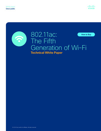
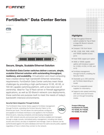
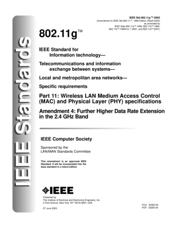
802.11ac PHYChannelization4 802.11ac PHY802.11ac plans to re-use 11n (&11a) details where possible. This is advantageous forensuring backwards compatibility and co-existence and also allows the 11acdevelopers to focus on the new features that are needed to achieve the throughputrequirements. For example, the 11ac PHY is based on the well known OFDM(Orthogonal Frequency Division Multiplexing) PHY used for 11a and 11n and willmaintain the same modulation, interleaving and coding architecture of 11n. However,some modifications and new 11ac features/parameters are necessary to meet 11ac’sgoals.802.11ac (aka VHT, Very High Throughput) devices are required to support 20, 40,and 80 MHz channels and 1 spatial stream. Several optional features are also definedin 802.11ac: Wider channel bandwidths (80 80 MHz and 160 MHz)Higher modulation support (optional 256QAM)2 or more spatial streams (up to 8)MU-MIMO (Multi-User MIMO)400 ns short guard intervalSTBC (Space Time Block Coding)LDPC (Low Density Parity Check)An 11ac device making use of only the mandatory parameters (80 MHz bandwidth, 1spatial stream, and 64 QAM 5/6) will be capable of a data rate of 293 Mbps while adevice that implements all optional parameters (8 spatial streams and 256 QAM 5/6with a short guard interval) will be able to achieve almost 3.5Gbps.4.1 ChannelizationWhen the OFDM PHY was introduced to 802.11, the channel bandwidth was 20MHzwith later amendments adding support for 5 and 10MHz bandwidths. The 802.11namendment added support for an optional 40MHz channel. 802.11ac will includesupport for 80MHz bandwidth as well as an optional 160MHz bandwidth. The 11acdevice is required to support 20, 40, and 80 MHz channel bandwidth reception andtransmission. The 80MHz channel will consist of two adjacent, non-overlapping 40MHzchannels. The 160MHz channels will be formed by two 80MHz channels which maybe adjacent (contiguous) or non-contiguous.“Channelization for 11ac” (See [8]) provides a nice background of the 11ac channelallocation for the US (Figure 1) and for Europe and Japan (Figure 2). Since therelease of that contribution, the FCC has approved the use of channel 144 in the US.(See Annex E of [16].) Figure 1 reflects this additional 20 MHz channel and theresulting additional 40 MHz channel and 80 MHz channel for 11ac for US and for theglobal operating class.1MA192 7eRohde & Schwarz802.11ac Technology Introduction 5
802.11ac PHYChannelizationFigure 1: US and Global Operating Class Channel IEEE channel #20 MHz5330 5490MHz MHz36404448525660645170MHz40 MHz80 MHz160 MHzFigure 2: Europe and Japan Class Channel AllocationTo signal the VHT bandwidth and operating frequencies 4 fields are used: Current Channel Bandwidth: Provides the channel bandwidth and could be20MHz, 40 MHz, 80 MHz, 160 MHz, and 80 80 MHz.Current Channel Center Frequency Index 1:o For 20, 40, 80 or 160 MHz bandwidths, this provides the channelcenter frequencyo For 80 80 MHz, this provides the center frequency of the primarysegment.Current Channel Center Frequency Index 2:o For 20, 40, 80 or 160 MHz bandwidths, this is undefined.o For 80 80 MHz, this provides the center frequency of the secondarysegment.Current Primary 20 MHz Channel: Provides the location of the primary 20MHzchannel. All channel bandwidths will have a primary 20 MHz channelassigned.These parameters are sent in the PLME MIB (Physical Layer Management EntityManagement Information Base) and are used along with the channel startingfrequency given in the Country Information and Regulatory Classes Annex of the802.11 standard [13] in the following equations to determine channel center frequencyand the frequency for the 20MHz primary subchannel:Channel center frequency [MHz] Channel starting frequency 5 * Current Channel Center Frequency IndexPrimary 20 MHz channel center frequency [MHz] Channel starting frequency 5 * Current Primary 20 MHz Channel1MA192 7eRohde & Schwarz802.11ac Technology Introduction 6
802.11ac PHYFrom Bandwidth to OFDM SubcarriersA few examples (from [9]) will help to illustrate how these parameters work to providethe center frequency and bandwidth: (Since a VHT STA operates in 5GHz band, theexamples will assume a regulatory class that has a channel starting frequency 5GHz.)Example 1:A channel specified byCurrentChannelBandwidth 80 MHzCurrentChannelCenterFrequencyIndex1 42CurrentPrimary20MHzChannel 36is an 80 MHz channel withChannel center frequency 5 GHz 5 * 42 5210 MHzPrimary 20 MHz center freq 5 GHz 5 * 36 5180 MHzExample 2:A channel specified byCurrentChannelBandwidth 80 80 MHzCurrentChannelCenterFrequencyIndex1 155CurrentChannelCenterFrequencyIndex2 106CurrentPrimary20MHzChannel 161is an 80 80 MHz channel withChannel center freq (Primary) 5 GHz 5 * 155 5775 MHzChannel center freq (Secondary) 5 GHz 5 * 106 5530 MHzPrimary 20 MHz channel center freq 5 GHz 5 * 161 5805 MHz4.2 From Bandwidth to OFDM Subcarriers802.11ac uses OFDM (Orthogonal Frequency Division Multiplexing) just as 802.11aand 802.11n do. (In fact 11ac ‘reuses’ much of the existing (legacy) 802.11a and802.11n specifications modifying where necessary to achieve the 11ac goals.) OFDMuses equally spaced subcarriers to transmit data, and the number of subcarriers in the11ac signal depends on the bandwidth as shown in Table 1. The subcarriers that arenot used for transmitting the signal are null subcarriers which are used for DCsubcarrier(s) or guard subcarriers. The DC subcarrier (subcarrier 0) is nulled to reduceproblems from analog/digital converters and carrier feedthrough.1MA192 7eRohde & Schwarz802.11ac Technology Introduction 7
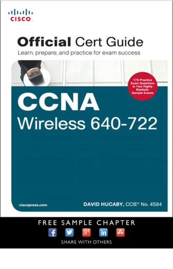
802.11ac PHYFrame FormatTable 1: Subcarriers per 11ac Transmission BandwidthBandwidth (MHz)204080160Number of Subcarriers6412825651280 80256 per 80MHz ChanSubcarriers Transmitting Signal-28 to -1 and 1 to 28-58 to -2 and 2 to 58-122 to -2 and 2 to 122-250 to-130, -126 to -6,6 to 126 and 130 to 250-122 to -2 and 2 to 122Because VHT devices are required to co-exist with existing legacy devices (e.g. 11aand 11n) and because 11ac devices will support 20, 40, and 80 MHz bandwidths, VHTwill send the same preamble in each 20 MHz sub band so that all 802.11 devices willbe able to synchronize to the packet. (See 4.3.1 for more information on thepreambles.) This introduces a problem of high PAPR (Peak to Average Power Ratio)which reduces the efficiency of power amplifiers. To mitigate this effect, thesubcarriers of the upper 20 MHz subbands are rotated as shown in Table 2:Table 2: Subcarrier Rotation per Signal BandwidthBandwidth (MHz)20408016080 80Rotated SubcarriersN/A³0³-64-192 to -1 and ³64Same as 80 MHz for each 80 MHz segmentRotation Value90 degrees (j)180 degrees (-1)180 degrees (-1)Same as 80MHzThose familiar with the 802.11n-2009 will recognize the 40 MHz subcarrier rotation asthe same as the 11n 40MHz bandwidth case.4.3Frame FormatFigure 3: VHT Mixed Format PPDUThe 802.11ac frame format is shown in Figure 3 and begins as expected with apreamble. The first 3 fields are L-STF (Short Training Field), L-LTF (Long TrainingField) and L-SIG (Signal). The L-STF and L-LTF contain information that allows thedevice to detect the signal, perform frequency offset estimation, timing synchronization,etc. The 'L-' stands for 'legacy' and the details of the sequences used in these fields forthe 20 MHz signals are the same as the legacy 11a and 11n preamble fields whichallows for all 802.11 devices to synchronize to the signal. In addition, the L-SIG fieldincludes information regarding the length of the rest of the packet. This means that all1MA192 7eRohde & Schwarz802.11ac Technology Introduction 8
802.11ac PHYFrame Formatdevices including the legacy devices will know that a packet of a given length is beingtransmitted.The next fields in the packet beginning with VHT are new to 11ac. (VHT 11ac andstands for Very High Throughput.) The VHT-SIG-A field contains two OFDM symbols.The first symbol is modulated using BPSK, so any 11n device listening will think thatthe packet is an 11a. The second symbol uses a 90 degree rotated BPSK whichallows the VHT device to know that this is an 11ac packet. Important information iscontained in the bits of these two symbols such as bandwidth mode, MCS (Modulationand Coding Scheme) for the single user case, number of space time streams, etc.The legacy fields and the VHT-SIG-A fields are duplicated over each 20 MHz of thebandwidth and the appropriate phase rotation is applied (see 4.2)After the VHT-SIG-A, the VHT-STF is sent. The primary function of the VHT-STF is toimprove automatic gain control estimation in a MIMO transmission.The next 1 to 8 fields of the packet are the VHT-LTFs. These are used for estimatingthe MIMO channel and then equalizing the received signal. Because the number ofLTFs sent is greater than or equal to the number of spatial streams per user, they arecalled ‘resolvable LTFs’.The VHT-SIG-B is the last field in the preamble before the data field is sent. VHT-SIGB is BPSK modulated and provides information on the length of the useful data in thepacket and in the case of MU-MIMO provides the MCS. (The MCS for single usercase is transmitted in VHT-SIG-A.)Appropriate phase rotation is applied to each 20 MHz subband in the VHT-STF, VHTLTF, and VHT-SIG-B. (See 4.2)Following the preamble, the data symbols are transmitted. These, too, implement thephase rotation in the upper 20 MHz subbands.1MA192 7eRohde & Schwarz802.11ac Technology Introduction 9
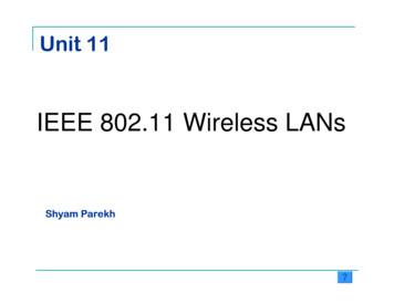
802.11ac PHYFrame Format4.3.1 VHT Preamble fields in detail4.3.1.1VHT SIG-AVHT auto-detectionFigure 4: VHT SIG-A symbols modulationThe VHT SIG A symbols immediately follow the legacy portion of the preamble andcontains information needed by all STAs (stations) and for the 11ac devices to decodethe rest of the VHT packet. The SIG-A symbols use the long GI (Guard Interval) andare BCC encoded with R 1/2 The first symbol is BPSK modulated and means that an11n receiver will think that the packet is an 11a packet and will ignore. The secondsymbol is BPSK rotated by 90 degrees (QBPSK) (as shown in Figure 4) and allows forauto-detection of VHT packet by the VHT STA (because the VHT device will know thatit is an 11ac packet based on the QBPSK dbit 8bit 9VHTSIG-A2Codingbits 2,3bits4.7Short GIbits 0,1bit 22bit 23bits13.21bits10.12VHTSIG-A1bits4.9bit 2bit 3bits 0,1ReservedSTBCTXOP PSReservedThe VHT-SIG-A symbols contain 24 bits each. 8 bits are used for CRC (CyclicRedundancy Check) and 6 bits are tail bits for the encoder. The information providedin the remaining 34 bits of the VHT-SIG A are needed for VHT devices to read the VHTpacket. Figure 5 shows the VHT-SIG-A format for the single user case with thenumber of bits used for each of the fields and Table 3 describes the field values.Figure 5: VHT SIG-A Format (Single User)1MA192 7eRohde & Schwarz802.11ac Technology Introduction 10
802.11ac PHYFrame FormatTable 3: VHT SIG-A Fields (Single User)VHT-SIG-A1 Fields (Single User)FieldBWVHT-SIG-A2 Fields (Single User)Description/ValueFieldDescription/ValueShort GIBit 0 (B0) 0: Data Field does not use short guard intervalPPDU Bandwidth00: 20 MHz01: 40 MHz1: Data Field uses short guard intervalBit 1 (B1) 1: short GI is uses and number of symbols mod 10 910: 80 MHz11: 160 MHz or 80 80 MHzReservedSTBC0: otherwiseCodingSet to 1.Bit 2 (B2) 0: BCCSpace Time Block Coding1 if all streams use STBC1: LDPCBit 3 (B3) 1: if LDPC encoding results in extra OFDM symbol0 otherwiseGroup ID0 if packet is addressed to an AP or for a mesh STA0: otherwiseMCS0 if packet is addressed to a mesh STA111111 (63) otherwiseNSTSMCS Index0: BPSK 1/2Provides the number of space time streams (STS)1: QPSK 1/20: 1 STS2: QPSK 3/41: 2 STS3: 16-QAM 1/22: 3 STS4: 16-QAM 3/43: 4 STS5: 64-QAM 2/34: 5 STS6: 64-QAM 3/45: 6 STS7: 64-QAM 5/66: 7 STS8: 256-QAM 3/47: 8 STSPartial AID9: 256-QAM 5/6BeamformedPartial Association Identifieran abbreviated indication of the intended recipient of the frameAn AP assigns an AID to a STA during association1: Beamforming steering matrix is applied0: otherwiseIf non-AP VHT STA,TXOP PSReserved. Set to 1.NOT ALLOWEDReservedCRCTailIf VHT AP,Set to 1.Cyclic Redundancy CheckSet to 0. (used to end the trellis of the convolutional decoder)0: AP allows STAs to enter doze state in TXOP PS1: OtherwiseReservedSet to 1.To accommodate multi-users (up to 4 are possible) some of the VHT-SIG-A fields aremodified to signal user specific information. Figure . shows the number of bits perfield with bits that are intended for a specific user indicated with colors (user 0 specificbits are shaded in plum; user 1 specific bits are shaded in red; user 2 specific bits areshaded in green; and user 3 specific bits are in blue). Table explains the fields inmore detail.Format of MU VHT-SIG-A1 and VHT-SIG-A2User 0User 1Tail Bitsbits18.23CodingShort GIReservedReservedbits10.17bits19.21CRCbit 8bit 9bits16.18User 3VHTSIG-A2bits13.15MCSbits4.7NSTSbits 2,3NSTSbits 0,1NSTSbit 22bit 23NSTSVHTSIG-A1bits4.9Group IDbit 2bit 3bits 0,1BWbits10.12ReservedSTBCTXOP PSReservedUser 2Figure 6: VHT-SIG-A Format (Multi-User)1MA192 7eRohde & Schwarz802.11ac Technology Introduction 11
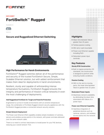
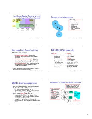
802.11ac PHYFrame FormatTable 4: VHT-SIG-A Fields (Multi-User)VHT-SIG-A1 Fields (Multi-User)FieldBWDescription/ValuePPDU BandwidthVHT-SIG-A2 Fields Multi User)FieldShort GIDescription/ValueBit 0 (B0) 0: Data Field does not use short guard interval00: 20 MHz01: 40 MHz1: Data Field uses short guard intervalBit 1 (B1) 1: short GI is uses and number of symbols mod 10 910: 80 MHz11: 160 MHz or 80 80 MHzReservedSTBCSet to 1.0: otherwiseCodingBit 2 (B2) If packet intended for user 0 (ie if NSTS field is non-zero)Space Time Block Coding1 if all streams use STBC0: User 0 uses BCC0 otherwiseGroup ID1: User 0 uses LDPCValue range: 1-62; indicates intended MU groupIf packet is not intended for user 0 (ie if NSTS field zero)(The group definitions are established by AP beforeReserved. Set to 1.Bit 3 (B3) 1: if LDPC results in extra OFDM symbol for at least 1 usertransmission of a MU frame and provide information suchas a user's position within a group.)NSTS(Per User)Provides the number of space time streams (STS) per user0: otherwiseMCS0: 0 STS0: User n uses BCC2: 2 STS1: User n uses LDPC3: 3 STSIf packet is not intended for user 0 (ie if NSTS field zero)4: 4 STSReserved. Set to 1.values 5-7 are reservedTXOP PSNOT ALLOWEDBit 4 is for user 1If non-AP VHT STA,Bit 5 is for user 2Reserved. Set to 1.Bit 6 is for user 3If VHT AP,0: AP allows STAs to enter doze state in TXOP PS1: OtherwiseReserved4.3.1.2Set to 1.If data is present for user n(ie if NSTS field for that user (user n) is non-zero)1: 1 STSBit 7 is reserved and set to 1.ReservedReservedCRCTailSet to 1.Set to 1.Cyclic Redundancy CheckSet to 0. (used to end the trellis of the convolutional decoder)VHT STFThe VHT STF (Short Training Field) is used to improve the automatic gain control in aMIMO transmission. The frequency domain sequence for the 20MHz and 40 MHzbandwidth are the same as in 20.3.9.3.3 of Standard 802.11n-2009:The VHT STF for the 80MHz case is formed by using the S-58,58 sequence as follows:VHTS 122 ,122 VHTS 58 , 58 , 0, 0, 0, 0, 0, 0, 0, 0, 0, 0, 0, VHTS 58 ,58 In the 80 80 MHz case, each 80 MHz segment uses the VHTS-122,122.In the 160MHz case, the sequence is:VHTS 250,250 VHTS 122,122 , 0, 0, 0, 0, 0, 0, 0, 0, 0, 0, 0, VHTS 122 ,122 What does this look like in the ‘real world’? The numbered subscripts refer to thesubcarrier. So, S-26,26 denote the subcarriers -26, -25, -24 ., 0, 24, 25, 26 andthe values in parenthesis gives the corresponding value of that subcarrier. Forexample, subcarrier -26 has 0 amplitude, subcarrier -25 has 0 amplitude, subcarrier 24 has amplitude sqrt(1/2)(1 j) and so forth. If one observed the signal in thefrequency domain on a spectrum analyzer, one would only ‘see’ the subcarriers thathave a non-zero value as shown in Figure 7.1MA192 7eRohde & Schwarz802.11ac Technology Introduction 12
802.11ac PHYFrame FormatSTF ‘on’SubcarriersFigure 7: VHT STF Preamble Field Spectrum Analyzer DisplayNote that the VHT STF always uses the long guard interval.4.3.1.3VHT LTFThe VHT LTF (long training fields) are used by the receiver to estimate the MIMOchannel and equalize the received signal. The number of LTF symbols sent in apacket depends on the number of space time streams: one LTF for one space timestream, two LTFs for two space time streams, four LTFs for three or four space timestreams, six LTFs for five or six space time streams, eight LTFs for seven or eightspace time streams.The VHT-LTF consists of data subcarriers with a value (-1, 0, or 1) applied to eachtone (i.e. subcarrier). (The sequence of values is defined in the 11ac amendment).The VHT-LTF may be quite long as the number of space time streams increase (i.e.the MIMO order increases). Unlike the legacy LTF, pilot tones are inserted into theVHT-LTF symbols for phase tracking to compensate for residual frequency error andphase noise that can degrade the OFDM signal and lead to channel estimation errorsat the receiver. ([14])The location of the pilots depends on the bandwidth of the signal (from [9]) and is givenin Table 5:1MA192 7eRohde & Schwarz802.11ac Technology Introduction 13
802.11ac PHYFrame FormatTable 5: Subcarrier Indices for VHT-LTF PilotsTransmission Bandwidth20 MHz40 MHz80 MHz160 MHzSubcarrier Indices of Pilot Tones 7, 21 11, 25, 53 11, 39, 75, 103 25, 53, 89, 117, 139, 167, 203, 231The tone (subcarrier) is then mapped to each space time stream using a matrix P fordata subcarriers or a matrix R for pilot subcarriers. The R matrix is simply a rowrepetition matrix which means that all space-time streams of the pilot subcarriers inVHT-LTF symbols will have the same pilot values.After mapping, the receiver is able to use the pilot subcarriers to track the phase andfrequency offset of the LTF symbols so that a more accurate channel estimation ispossible from the data subcarriers.Similar to the VHT-STF, the VHT-LTF will always use the long guard interval.4.3.1.4VHT 50.160.18bits20.2521.2623.282 or 3bitsbits0.160.180.20ReservedThe VHT-SIG-B follows the VHT-LTF. It is one symbol that is BPSK modulated andcontains 26 bits in a 20MHz packet, 27 bits in a 40MHz packet and 29 bits in an 80MHz, 160 MHz, or 80 80 MHz packet. The format for the VHT-SIG-B depends onwhether the packet is for a SU-MIMO or for a MU-MIMO as shown in Figure 8.Figure 8: VHT-SIG-B FormatBy varying the size of the length fields, a consistent packet duration of 5.46 ms can bemaintained regardless of channel width or if it is for a SU or MU.These bits are repeated for the higher bandwidths as shown in Figure 9 (from [9]). Apad bit is necessary at the end of the 80MHz repetition to accommodate all 117 tones(29*4 1).1MA192 7eRohde & Schwarz802.11ac Technology Introduction 14
802.11ac PHY802.11ac Data Field for Single User with BCCFigure 9: SIG-B bits for 20, 40, 80, 80 80 and 160 MHz4.4 802.11ac Data Field for Single User with BCC802.11ac will use the 802.11n modulation, interleaving and coding architecture.However, there are a few differences to the 11n specification. 11ac and 11n requiresdevice support for BPSK, QPSK, 16QAM and 64QAM modulation, but 11ac adds anoptional 256 QAM. The second difference is in the number of defined MCS Indices. 10single user MCS are defined in 11ac as shown in Table 6. Note that this is significantlylower than the 77 MCS indices specified in 11n. 11n required 77 because 11nsupported "unequal" modulations, e.g. a single user might get BPSK on one streamand 16QAM on another. (See tables 20-38 to 20-43 of [10]). For 11ac, the decision toonly allow equal modulations makes sense because in practice no 11n devicessupported unequal modulations and given the additional options in .11ac (e.g. 256QAM, 160MHz bandwidth), the number of possibilities would be QAM16-QAM64-QAM64-QAM64-QAM256-QAM256-QAMCoding Rate1/21/23/41/23/42/33/45/63/45/6Table 6: 11ac Single User MCS Indices1MA192 7eRohde & Schwarz802.11ac Technology Introduction 15
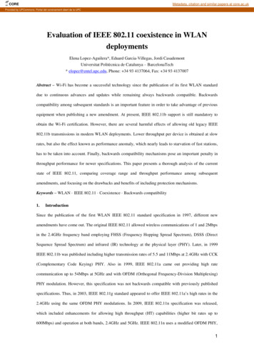
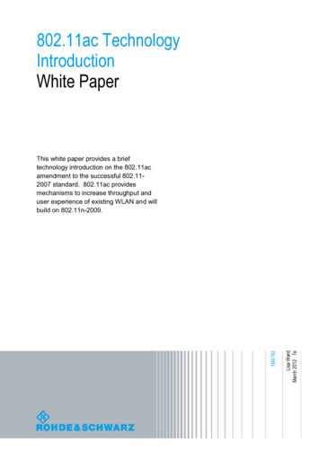
802.11ac PHY802.11ac Transmitter Specification4.5 802.11ac Transmitter Specification4.5.1 Transmit Spectrum MaskThe 11ac device must meet the spectral mask given in the 11ac amendment and anyapplicable regulatory requirements. The measurement for the 11ac mask is madeusing a 100 KHz resolution bandwidth (RBW) and a 30 KHz video bandwidth (VBW).The mask for 20, 40, 80, and 160 MHz transmissions is shown in Figure 10 with thevalues of A, B, C, and D given in Table 7. The mask ‘amplitude’ is given in units of dBrwhich means dB relative to the maximum spectral density of the signal.Figure 10: Spectral Mask for 20, 40, 80 and 160 MHz ChannelsTable 7: Frequency Offsets for Spectral Mask RequirementChannel Size20 MHz40 MHz80 MHz160 MHz1MA192 7eA9 MHz19 MHz39 MHz79 MHzB11 MHz21 MHz41 MHz81 MHzC20 MHz40 MHz80 MHz160 MHzRohde & SchwarzD30 MHz60 MHz120 MHz240 MHz802.11ac Technology Introduction 16
802.11ac PHY802.11ac Transmitter SpecificationIn the case of non-contiguous 80 80 MHz, the 80 MHz masks are used for each 80MHz signal and the value of the mask where the two non-contiguous 80 MHz masksoverlap are given in Table 8. The mask construction for two 80 MHz non-contiguoussignals separated by 160 MHz is shown in Figure 11.Table 8: 80 80 MHz Non-Contiguous Spectrum Mask ValuesStep123Frequency Overlap Mask ValuesBoth masks have values between -20dBr and -40 dBrN
The IEEE 802.11 group has continued to build and improve on the earlier a/b and g with the official approval of 802.11n in 2009 and other enhancements such as 802.11w, 11k, etc. An IEEE Standards in Communications and Networking article, "The IEEE 802.11 Universe" [1] provides a very good overview of past a