Transcription
IMPORTANT SAFETY INSTRUCTIONSSAVE THESE INSTRUCTIONSPLEASE READ THE ENTIRE CONTENTS OF THIS MANUAL PRIORTO INSTALLATION AND OPERATION. BY PROCEEDING WITH LIFTINSTALLATION AND OPERATION YOU AGREE THAT YOU FULLYUNDERSTAND ANDCOMPREHEND THE FULL CONTENTS OF THISHANDBOOK. FORWARD THIS MANUAL TO ALL OPERATORS. FAILURE TOOPERATE THIS EQUIPMENT AS DIRECTED MAY CAUSE INJURY OR DEATH.MAN REV C 04-10-15P/N 5900381INSTALLATION AND OPERATION MANUAL1,000 POUND CAPACITYMOTORCYCLE / ATV LIFTMODEL:RML-600XLRECEIVINGThe shipment should be thoroughly inspected as soon as itis received. The signed Bill of Lading is acknowledgementby the shipping carrier as receipt of this product as listedin your invoice as being in a good condition of shipment. Ifany of these goods listed on this Bill of Lading are missingor damaged, do not accept goods until the shipping carriermakes a notation on the freight bill of the missing ordamaged goods. Do this for your own protection.BE SAFEYour new tire changer was designed and built with safetyin mind. However, your overall safety can be increased withproper training and thoughtful operation on the part of theoperator. DO NOT operate or repair this equipment withoutreading this manual and the important safety instructionsshown inside. Keep this operation manual near the tirechanger at all times. Make sure that ALL USERS read andunderstand this manual.1645 Lemonwood Dr.Santa Paula, CA. 93060, USAToll Free 1-800-253-2363Tel: 1-805-933-9970Fax: 1-805-933-9160www.bendpak.com1
1,000 POUND CAPACITY - MOTORCYCLE / ATV LIFTThis instruction manual has been prepared specifically for you. Your new Ranger Motorcycle Lift is the product ofcontinuing research, testing and development; it is the most technically advanced motorcycle lift on the market today.The manner in which you care for and maintain your motorcycle lift will have a direct effect on its overall performanceand longevity.PRODUCT WARRANTYDuration: From the date of purchase by the original Purchaser or 12 months from the date of shipment or whichevercomes first. One Year (12-Months) Warranty on equipment structure* One Year (12-Months) Warranty on operating components One Year (12-Months) Free-Shipping** on ground-freight charges related to warranty performanceLimited Warranty1. Who gives this warranty (Warrantor): BendPak/Ranger, 1645 Lemonwood Dr., Santa Paula, CA 930602. Who receives this warranty (Purchaser): The original Purchaser (other than for purpose of resale)3. What products are covered by this warranty: Any Ranger brand Transmission Jack, Floor Jack, Motorcycle LiftPlatform, Specialty Jack, Shop Crane, Cart/Dolly, Jack Stand, Hydraulic Press, Hose Reel, Shop Equipment***4. What is covered under this warranty: manufacturer defects due to material and/or workmanship with the exceptionsnoted below.5. What is not covered under this warranty:a. Any failure that results from Purchaser’s abuse, neglect or failure to operate, maintain or service product inaccordance with instructions provided in the owner’s manual(s) suppliedb. Any damage caused by using equipment beyond rated capacity and/or capabilityc. Items or service normally required to maintain the product, i.e. lubricants, oil, etc.d. Items considered general wear parts such as rubber or plastic pads/protectors, worn casters/wheels, plastic trays, etc.unless wear or failure is a direct result of manufacturer defect due to material and/or workmanshipe. Any component damaged in shipment or any failure caused by installing or operating equipment under conditions notin accordance with installation and operation guidelines or damaged by contact with tools or surroundingsf. Any component failure caused by rain, excessive humidity, corrosive environments or other contaminantsg. Rusted components due to improper maintenance or corrosive environmentsh. Cosmetic defects that do not interfere with product functionalityi. Damage due to incorrect voltage or improper wiringj. Any incidental, indirect, or consequential loss, damage, or expense that may result from any defect, failure, ormalfunction of a Ranger productk. All electrical components are guaranteed for one year against defects in workmanship and/or materials when the lift isinstalled and used according to specifications6. Responsibilities of Warrantor under this warranty: Repair or replace with either new or reconditioned unit atWarrantor’s option, component and/or unit which is defective, has malfunctioned and/or failed to conform within durationof the warranty period.7. Responsibilities of Purchaser under this warranty:a. Provide dated proof of purchase and maintenance recordsb. In some cases, components may be required to be shipped to the nearest BendPak/Ranger Authorized ServiceCenter. Freight costs, after 12 months, must be borne by the Purchaser.c. Use reasonable care in the operation and maintenance of the products as described in the owner’s manual(s).8. When Warrantor will perform repair or replacement under this warranty: Repair or replacement will be scheduled andserviced according to the normal work flow at the servicing location, and depending on the availability of replacementparts. For more information please visit: www.bendpak.com/Ranger-Warranty.pdf. (Section: Shop Equipment Warranty).WARRANTY IS NOT VALID UNLESS WARRANTY CARD IS RETURNED.IMPORTANT NOTICETHESE INSTRUCTIONS MUST BE FOLLOWED TO Ensure PROPER INSTALLATION AND OPERATION OF YOURLIFT. FAILURE TO COMPLY WITH THESE INSTRUCTIONS CAN RESULT IN SERIOUS BODILY HARM AND VOIDPRODUCT WARRANTY. MANUFACTURER WILL ASSUME NO LIABILITY FOR LOSS OR DAMAGE OF ANY KIND,EXPRESSED OR IMPLIED, RESULTING FROM IMPROPER INSTALLATION OR USE OF THIS PRODUCT.PLEASE READ ENTIRE MANUAL PRIOR TO INSTALLATION AND OPERATION2
IMPORTANT NOTICEOWNER’S RESPONSIBILITYDo not attempt to install this lift if you have never beentrained on basic motorcycle lift installation procedures.Never attempt to lift components without proper liftingtools such as a forklift or crane. Stay clear of any movingparts that can fall and cause injury. Theseinstructions must be followed to ensure proper installationand operation of your lift. Failure to comply with theseinstructions can result in serious bodily harm and voidproduct warranty. Manufacturer will assume no liability forloss or damage of any kind, expressed or impliedresulting from improper installation or use of this product.To maintain the lift and user safety, the responsibility ofthe owner is to read and follow these instructions:tttttPLEASE READ ENTIRE MANUALPRIOR TO INSTALLATION.tttDEFINITIONS OFHAZARD LEVELS tFollow all installation and operation instructions.Make sure installation conforms to all applicable Local,State, and Federal Codes, Rules, and Regulations;such as State and Federal OSHA Regulations andElectrical Codes.Carefully check the lift for correct initial function.Read and follow the safety instructions. Keep themreadily available for machine operators.Make certain all operators are properly trained, knowhow to safely and correctly operate the unit, and areproperly supervised.Allow unit operation only with all parts in place andoperating safely.Carefully inspect the unit on a regular basis andperform all maintenance as required.Service and maintain the unit only with authorized orapproved replacement parts.Keep all instructions permanently with the unit andall decals on the unit clean and visible.Identify the hazard levels used in this manual with thefollowing definitions and signal words:BEFORE YOU BEGINNOTIFY THE CARRIER AT ONCE if any hidden loss ordamage is discovered after receipt and request the carrierto make an inspection. If the carrier will not do so, preparea signed statement to the effect that you have notified thecarrier (on a specific date) and that the carrier has failed tocomply with your request.Watch for this symbol as it means: Immediate hazardswhich will result in severe personal injury or death.IT IS DIFFICULT TO COLLECT FOR LOSS OR DAMAGEAFTER YOU HAVE GIVEN THE CARRIER A CLEARRECEIPT. Support claim with copies of the bill of lading,freight bill, invoice, and photographs, if available. Ranger’swillingness to assist in helping you process your claim doesnot make Ranger responsible for collection of claims orreplacement of lost or damaged materials.Watch for this symbol as it means: Hazards or unsafepractices which could result in severe personalinjury or death.Watch for this symbol as it means: Hazards or unsafepractices which may result in minor personal injury,product or property damage.3
INSTALLER / OPERATORPLEASE READ AND FULLYUNDERSTAND. BY PROCEEDINGYOU AGREE TO THE FOLLOWING:Failure to follow Danger, Warning, and Cautioninstructions may lead to serious personal injury or deathto operator or bystander or damage to property.t I have visually inspected the site where the lift is to beinstalled and verified the concrete to be in goodcondition and free of cracks or other defects. I understandthat installing a lift on cracked or defective concrete couldcause lift failure resulting in personal injury or death.Please read the entire manual prior to installation.Do not operate this machine until you have read andhave understood all of the Danger, Warning and Cautionalerts in this manual. For additional copiesor further information, contact:t I understand that a level floor is required for properinstallation and level lifting.tI understand that I am responsible if my floor is ofquestionable slope and that I will be responsible for allcharges related to pouring a new, level concrete slab ifrequired.BendPak Inc.1645 Lemonwood Dr.t I will assume full responsibility for the concrete floorand condition thereof, now or later, where the aboveequipment model is to be installed. Failure to followDanger, Warning, and Caution instructions may lead toserious personal injury or death to operator or bystanderor damage to property.Santa Paula, CA. 930601-805-933-9970www.bendpak.comINSTALLER / OPERATORPROTECTIVE EQUIPMENTt I understand that Ranger lifts are designed to beoperated in indoor locations only. Failure to followinstallation instructions may lead to serious personal injuryor death to operator or bystander or damage to propertyor lift.Personal protective equipment helps makes installationand operation safer, however, it does not take the placeof safe operating practices. Always wear durable workclothing during any installation and/or service activity.Shop aprons or shop coats may also be worn, howeverloose-fitting clothing should be avoided.Tight-fitting leather gloves are recommended to protectthe technician’s hands when handling parts. Sturdyleather steel-toe work shoes and oil resistant soles shouldbe used by all service personnel to help prevent injuryduring typical installation and operation activities.Eye protection is essential duringinstallation and operation activities. Safetyglasses with side shields, goggles, or faceshields are acceptable. Back belts providesupport during lifting activities and arealso helpful in providing worker protection.Consideration should also be given to the use of hearingprotection if service activity is performed in an enclosedarea, or if noise levels are high.THIS SYMBOL POINTS OUT IMPORTANT SAFETY INSTRUCTIONS WHICH IF NOT FOLLOWEDCOULD ENDANGER THE PERSONAL SAFETY AND/OR PROPERTY OR YOURSELF AND OTHERSAND CAN CAUSE PERSONAL INJURY OR DEATH. READ AND FOLLOW ALL INSTRUCTIONS INTHIS MANUAL BEFORE ATTEMPTING TO OPERATE THIS MACHINE.4
IMPORTANTSAFETY INSTRUCTIONSIMPORTANT SAFETY INSTRUCTIONSRead these safety instructions entirely. Do not attempt to install this lift if you have never been trainedon basic motorcycle lift installation procedures. Never attempt to lift components without proper lifting tools such asforklifts or cranes. Stay clear of any moving parts that may fall and cause injury. When using your garage equipment,basic safety precautions should always be followed, including the following:1. Read and understand all instructionsand all safety warnings before operatinglift.12. DO NOT override self-closing lift controls.2. Care must be taken as burns can occurfrom touching hot parts.14. ALWAYS make sure the safety is engaged beforeattempting to work on or near a vehicle.3. Do not operate equipment with a damaged pneumatichose or if the equipment has been dropped or damageduntil it has been examined by a qualified service person.15. MAINTAIN WITH CARE. Keep lift clean for better andsafer performance. Follow manual for proper lubricationand maintenance instructions. Keep control handlesand/or buttons dry, clean and free from grease and oil.13. Clear area if vehicle is in danger of falling.4. Do not let the pneumatic hose hang over the edge ofthe table or come in contact with hot manifolds or movingfan blades.16. Check for damaged parts. Check foralignment of moving parts, breakage ofparts or any condition that may affectoperation of lift. Do not use lift if anycomponent is broken or damaged.5. Care should be taken to arrange the pneumatic hoseso that it will not be tripped over or pulled.6. Adequate ventilation should be provided whenworking on operating internal combustion engines.17. NEVER remove safety related components from thelift. Do not use lift if safety related components are missingor damaged.7. Keep hair, loose clothing, fingers, and all parts of bodyaway from moving parts. Keep hands and feet clear of liftwhen lowering. Avoid pinch points.18. STAY ALERT. Use common sense and watchwhat you are doing. Remember, SAFETY FIRST.8. Use only as described in this manual. Use only manufacturer’s recommended attachments.19. USE LIFT CORRECTLY. Use lift in the proper manner.Never use lifting adapters other than what is approved bythe manufacturer.9. ALWAYS WEAR SAFETY GLASSES. Everyday eyeglasses only have impact resistant lenses, they are notsafety glasses.20. When the lift is being lowered, make sure everyone isstanding at least six feet away.10. Consider work environment. Keep work area clean.Cluttered work areas invite injuries. Keep areas well lit.21. Be sure there are no jacks, tools or any type of equipmentleft under the lift before lowering.11. Only trained operators should operate this lift. Allnon-trained personnel should be kept away from the workarea. Never let non-trained personnel come in contactwith, or operate lift.22. It is important that you know the load limit. Be careful thatyou do not overload the lift. If you are unsure what the loadlimit is, refer to this manual or contact the manufacturer.SAVE THESE INSTRUCTIONS5
tTOOLS REQUIREDOpen-End Wrench Set: SAE/Metrict Socket And Ratchet Set: SAE/MetricIMPORTANT NOTICETHESE INSTRUCTIONS MUST BE FOLLOWED TO ENSURE PROPER INSTALLATION AND OPERATION OF YOURLIFT. FAILURE TO COMPLY WITH THESE INSTRUCTIONS CAN RESULT IN SERIOUS BODILY HARM AND VOIDPRODUCT WARRANTY. MANUFACTURER WILL ASSUME NO LIABILITY FOR LOSS OR DAMAGE OF ANY KIND,EXPRESSED OR IMPLIED, RESULTING FROM IMPROPER INSTALLATION OR USE OF THIS PRODUCT.PLEASE READ ENTIRE MANUAL PRIOR TO INSTALLATIONSTEP 4STEP 1(Unpacking and Setup)(Selecting Site)Before installing your new lift, check the following.1.Open carton, then remove ramp and shipping boards.1. LIFT LOCATION: Always make sure that adequatespace is available for your new lift.2. OVERHEAD OBSTRUCTIONS: The area where thelift will be located should be free of overhead obstructionssuch as heaters, building supports, electrical lines etc.THE LIFT MAY BE DAMAGED AND/OR PERSONALINJURY MAY RESULT IF THE PRESSUREEXCEEDS THE MAXIMUM 100 PSI RATING.3. DEFECTIVE FLOOR: Visually inspect the site wherethe lift is to be installed and check for defective concrete.2.4. Your new Ranger Motorcycle / ATV Lift is designed forINDOOR INSTALLATION ONLY.3. With lift in the lowered position insert ramp mountingpins into holes at either end of table to mount ramp.STEP 2(Floor Requirements)4. Stand clear of lift table, and depress the UP side offoot valve to raise table.This lift must be installed on a solid level concrete floorwith no more than 3-degrees of slope. Failure to do socould cause personal injury or death.5. Engage Safety Bar and lower lift onto safety bydepressing the DOWN side of foot valve.Connect foot-operated air valve to 100 psi air supply.TO LOWER LIFT:A level floor is suggested for proper use and installationand level lifting. If a floor is of questionable slope, considera survey of the site and/or the possibility of pouring a newlevel concrete slab.1. Raise the lift slightly and lift the safety latch andlower to next position or to the floor.STEP 3(General Specifications)Main Lifting Table. 24” W x 79” LSide Extensions (Standard). 10” W x 79” LApproach Ramps. 10” W x 14” LExtended Approach Ramp. 13 3/4” W x 14” LLowered Height.7 1/16”Capacity.1000 lbVISUALLY CONFIRM THAT SAFETY LOCK ISENGAGED BEFORE ENTERING WORK AREA.REMAIN CLEAR OF ELEVATED LIFT UNLESS VISUALCONFIRMATION IS MADE THAT SAFETY LOCK ISFULLY ENGAGED AND THE LIFT IS LOWERED ONTOTHE SAFETY LOCK, REFER TO INSTALLATION /OPERATION MANUAL FOR PROPER SAFETY LOCKPROCEDURES AND / OR FURTHER INSTRUCTION.READ ENTIRE MANUAL AND COMPLY WITH ALLSAFETY AND SERVICE PRECAUTIONS. DEATH,PERSONAL INJURY AND / OR PROPERTY DAMAGEMAY OCCUR UNLESS INSTRUCTIONS AREFOLLOWED CAREFULLY.6
SAFE LIFTING / MAINTENANCE1.Step 5(Wheel Clamp Installation)Loads must be centered on table at all times.1. Align mounting holes of Left and Right Wheel Clampsand bolt to table with hardware provided. Align mountingholes of Tire Stop and bolt to table with hardware provided.2. Loads must be firmly positioned and secured on tableat all times.Step 6(10” Side Extension Installation)3. All moving parts have been lubricated at the factoryand should be re-lubricated every 6 months to preventgalling. Zerk grease fittings are located at each endof frame pivot shaft and at the top end of inside frameassembly.4.1. Insert pipes from extension panel package throughholes in lift table.2. Mount panels on ends of pipe on each side of tablewith ramp hole towards the outside.Lightly oil cylinder rod when it becomes dry.5. Lubricate piston and piston seal by pumping oilthrough the air bleed hole in the plate end of the cylinderevery 6 months.3. Secure ramp extensions to ramp with bolts provided.Make sure ramp hooks are positioned on the outside.6. Pivot shaft set screws should be checked frequentlyto ensure they are tight. These are located at the top endof the inside frame assembly.4. Insert eye bolt in drilled out hole and tighten with nut.Insert the other bolt, tighten down with nut. Put on thecaps and tighten.10” SIDE EXTENSIONS7
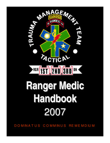
RML-600XLSAFE LIFTING GUIDEAdjustable ViseAssemblyLift TableSide ExtensionsSafety LatchDetent BarRampPneumatic CylinderFoot Valve1. Center load on table – 1000 lb. maximum.2. Connect to 100 PSI maximum shop air.3. Keep safety bar in position at all times – except when lowering.4. Keep hands and tools from under table.5. Do not mount table when in elevated position.6. Do not ride vehicle onto lift.7. Lift must be in the lowered position when transporting.8. Only trained operators should use lift.9. The working area should be sufficiently lit.10. Foot controller should be at least 3 feet away from liftduring raising and lowering operation.11. Lift is recommended for indoor use only.8
SAFE LIFT OPERATIONMotorcycle lifts are critical to the operation and profitability of your business. The safe use of this and other lifts in yourshop is critical in preventing employee injuries and damage to customer’s vehicles. Safe operation of a motorcycle liftrequires that only trained employees should be allowed to use the lift.TRAINING SHOULD INCLUDE, BUT NOT LIMITED TO:t Proper positioning of the vehicle on the table.t Use of the operating controls.t Understanding the lift capacity.t Proper use of jack stands or other load supporting devices.t Proper use, understanding and visual identification of safety lock devices and their operation.t Reviewing the safety rules.t Proper housekeeping procedures (lift area should be free of grease, oil, tools, equipment, trash, and other debris)t A daily inspection of the lift should be completed prior to its use. Safety devices, operating controls, lift arms andother critical parts should be inspected prior to using the lift.t All maintenance and repairs of the lift should be completed by following the manufacturer’s requirements. Lift repairparts should meet or exceed OEM specifications. Repairs should only be completed by a qualified lift technician.t The vehicle manufacturer’s recommendations should be used for spotting and lifting the vehicle.LIFT OPERATION SAFETYtttttttttttttttttttttIt is important that you know the load limit. Be careful that you do not overload the lift . If you are unsure what theload limit is, refer to this manual or contact the manufacturer.The center of gravity should be followed closely to what the manufacturer recommends.Always make sure you have proper overhead clearance. Additionally, check that attachments, (vehicle signs,pipes, antennas, etc.) are not in the way.Be sure that prior to the vehicle being raised the motorcycle is secured to the table.Prior to being raised, make sure there is no one standing closer than six feet from the lift.After positioning the vehicle on the lift, make sure the ignition is off, overhead obstructions are cleared, and the transmission is in neutral.The lift should be raised just until the vehicle’s wheels are about one foot off the ground. If contact with the vehicle isuneven or it appears that the vehicle is not sitting secure, carefully lower the lift and readjust.Always consider potential problems that might cause a vehicle to slip, i.e., heavy cargo, etc.Pay attention when walking under a vehicle that is up on the lift.DO NOT leave the controls while the lift is still in motion.DO NOT stand directly in front of the vehicle or in the bay when vehicle is being loaded into position.DO NOT Go near vehicle or attempt to work on the vehicle when being raised or lowered.REMAIN CLEAR of lift when raising or lowering vehicle.DO NOT rock the vehicle while on the lift or remove any heavy component from vehicle that may cause excessiveweight shift.Always lower the vehicle down slowly and smoothly.ONLY TRAINED OPERATORS should operate this lift. All non-trained personnel should be kept away from work area.Never let non-trained personnel come in contact with, or operate lift.USE LIFT CORRECTLY. Use lift in the proper manner. Never use lifting adapters other than what is approved by themanufacturer.DO NOT override self-closing lift controls.CLEAR AREA if vehicle is on danger of falling.STAY ALERT. Watch what you are doing. Use common sense. Be aware.CHECK FOR DAMAGED PARTS. Check for alignment of moving parts, breakage of parts or any condition that mayaffect its operation. Do not use lift if any component is broken or damaged.9
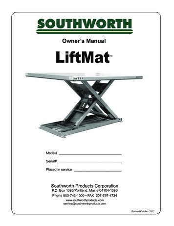
RML-600XLPARTS BREAKDOWN10
RML-600XLPARTS BREAKDOWNPart # DescriptionQty Part #DescriptionQty Part #DescriptionQty1Stop Plate131Cylinder161Revolver12Bolt M10x25632Retaining Ring462Joint13Nylon Ring233Piston163Nut44Adjustable Shelf134O-Ring164Frame/Cylinder Pivot Shaft15Bolt M8x16435O-Ring165Front Extension16Movable Vise Assy.136Seal Ring166Left Side Extension17Stationary Vise Assy.137Retaining Ring167Right Side Extension18Platform138Retaining Ring168Left Ramp Extension19Removable Plate139Piston Rod169Right Ramp Extension110Ramp140O-Ring270Support Pipe211Detent Bar141Shaft Bushing171Lifting Ring412Clevis Pin242Cam Roller Bearing472Bolt M8x25413R-Pin243O-Ring173Lock washer Ø8414Handle socket144Retaining Ring274Washer Ø8415Bolt M16x130245Front Cap175Nut M8416Washer646Nut176Pipe117Lock Nut M16447Air Hose177Pipe Sleeve218Lifting Arm148Foot-operated Air Valve178Pin419Bolt M16x80249Air Hose Connector179Bolt M10x20620Bolt M12x25150Retaining Ring121Press Ring151Wheel222Retaining Ring452Connection123O-Ring153Bolt M10x45224Lifting Arm154Cam Roller Bearing425Cylinder End Plate155O-Ring226Lock Nut M10256Cam Bearing Spacer227Nut M101657Roller228Lock Washer Ø10858Mobile Car129Washer Ø102059Lube Mouth430Stay Bolt460R-Pin211
p/n 590038112
on basic motorcycle lift installation procedures. Never attempt to lift components without proper lifting tools such as forklifts or cranes. Stay clear of any moving parts that may fall and cause injury. When using your garage equipment, basic safety precautio