Transcription
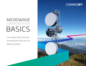
MICROWAVECOMMUNICATIONBASICSTHE THEORY, PRACTICES ANDTECHNOLOGIES THAT LINK THEPhoto: Robert Agua, TelikomWIRELESS WORLD
TABLE OF CONTENTSChapter 1IntroductionChapter 2Microwave basics andall about antennasChapter 3Microwave communicationand path designChapter 4The importance of patternsand regulatory complianceChapter 5Environmental considerationsChapter 6Mechanical and structural factorsChapter 7Antenna selection andmaximizing ROIChapter 8ConnectivityChapter 9Waveguide pressurizationChapter 10Installation and path alignmentChapter 11Millimeter microwavesChapter 12Referenceswww.commscope.com2
COUNT ON COMMSCOPE TO HELPYOU OVERCOME TODAY’S MOSTPRESSING NETWORK CHALLENGESAuthored by CommScope experts, this bookexplains how the fundamentals of microwavecommunications impact the capacity andreliability of your wireless network.A modern wireless network depends on multiplesystems, meshing together, to provide the customerwith a positive experience—one that’s transparent,fast and most of all, dependable. Microwavecommunications, used for backhaul applications thatmove site traffic on and off of the core network, canmake or break that positive customer experience.This book offers an accessible yet meaningful look intothe components, systems and practices that go into anefficient, reliable microwave communications network.“As an industry leader, CommScope is sharing whatwe’ve learned to help you overcome every networkchallenge—even if it’s just simple curiosity about thescience of microwave communications,” said MorganKurk, chief technology officer.TABLE OF CONTENTSMorgan Kurk,chief technology officerwww.commscope.com3
CHAPTER1Introduction:Microwave networks andthe insight that builds themTABLE OF CONTENTSwww.commscope.com4
CHAPTER1Introduction: Microwave networks and the insight that builds themMicrowave backhaulJOIN US AS WE TAKE THE NEXT LEAPFORWARD IN EFFICIENCY AND COSTThis book is released at an exciting time in the field,as new advances are pushing back the boundariesof performance, efficiency and cost in microwavecommunication networks.The use of microwavecommunications toaggregate and transmitcellular voice and datato and from the mainnetwork.CommScope has been at the forefront in development ofnew microwave antenna designs that feature low side lobesthat vastly improve interference resistance, which in turnboosts capacity and quality of service—all while reducingtotal cost of ownership for the operator.You’ll learn more about side lobes in Chapter 4 andelsewhere in this book—and you can always rely on yourpartners at CommScope for innovative thinking andindustry leadership.TABLE OF CONTENTSwww.commscope.com5
CHAPTER1Introduction: Microwave networks and the insight that builds themLine of sight (LOS)WHAT ARE MICROWAVES ANDHOW ARE THEY USED?Within the broader spectrum of radiofrequency (RF) communications, point-to-pointcommunications are usually carriedout using microwave frequencies between1 GHz and 100 GHz along line-of-sight (LOS)paths called links.A clear path—free of anyobstructions—betweenpoints of microwave signaltransmission and reception.LinkThe connection of twofixed microwave sites viaa line-of-sight (LOS) path.Also referred to as a “hop.”These frequencies and their propagation characteristicsallow the transmission of vast amounts of databetween remote communication sites without the needto lay cables between them.The characteristics of the antennas used in point-topoint communication allow the same frequencies tobe used throughout a system—that is, the system canemploy high frequency reuse. Careful link planning andmanagement make this possible without interferencebecoming a problem.These advantages give microwaves a special place inthe world of RF engineering, where they are used inpoint-to-point wireless communications networks,satellite communications, radar systems and even radioastronomy.TABLE OF CONTENTSwww.commscope.com6
CHAPTER1Introduction: Microwave networks and the insight that builds themA BRIEF HISTORY OF MICROWAVESThe first practical application of microwaves in acommunication system took place more than 80years ago. In the 1930s, an experimental microwavetransmission system was used to connect the UnitedKingdom with France—bridging the English Channelwithout cables. In the 1950s, AT&T built a 10-channelmicrowave radio relay system in the United States thatwas capable of carrying 5,400 long-distance calls perchannel, supporting a total of 54,000 simultaneouscallers. The emergence of television provided anotheropportunity, as network broadcasting was relayed tolocal affiliates across the country.In the 1980s, analog RF systems began giving wayto more efficient, higher-capacity digital systemsto accommodate rising traffic demand. Even then,microwave networks typically provided long-haulcommunications—but all that was to change withthe development of another ubiquitous consumerRF technology: the cellular telephone.TABLE OF CONTENTSBrief history1930sEarly microwave transmissionsystem was used to connect theUnited Kingdom with France1930sEmergence of televisionbroadcasting1950sAT&T built a 10-channelmicrowave radio relay systemin the US.1980sAnalog RF systems begangiving way to more efficient,higher-capacity digital systems1980sDevelopment of thecellular telephonewww.commscope.com7
CHAPTER1Introduction: Microwave networks and the insight that builds themMicrowave backhaulTHE CELLULAR REVOLUTIONThe worldwide proliferation of cellular networksintroduced a critical demand for new microwavebackhaul infrastructure; after all, a cell site could onlygenerate revenue if it could move its traffic to andfrom the rest of the network. Connecting individualsites to the main network called for a reliable,affordable and powerful means of transmitting largeamounts of aggregated data over the span of a fewkilometers—and its infrastructure would have to bequickly deployed to keep up with rising demand.well as voice and creating a consumer experience thathas led to nearly universal expectations of constant,reliable connectivity all over the world. As newnetwork technologies and standards emerged, pointto-point microwave communication has remained thebackbone of the entire model, connecting millions ofusers to their networks in a seamless tapestry coveringthe planet.The use of microwavecommunications toaggregate and transmitcellular voice and datato and from the mainnetwork.The telecommunications industry adopted a small,single-channel microwave radio system mounteddirectly onto the back of a smaller antenna. Thissolution provided the capacity the industry needed,but without the complex installation required bytraditional long-haul microwave systems.Since those early days, the wireless industry hascontinued to grow exponentially—moving data asTABLE OF CONTENTSwww.commscope.com8
CHAPTER1Introduction: Microwave networks and the insight that builds themTRUST A PROVEN PARTNER TOPUT IT ALL TOGETHERBeyond the basic theory and simplest applications,building microwave communication infrastructureinto wireless networks is a complicated task requiringbroad expertise across a number of technologiesand disciplines.We provide innovative solutions and practicalguidance for: Link planning Antennas Elliptical waveguide and connectivity solutions Pressurization Environmental considerations Installation and alignmentCommScope has been involved in microwavenetworks since the early 1950s. Our microwaveantenna solutions connect the world’s networks,much as the early railways connected cities andnations. Throughout the development of microwavecommunication, our innovative approach toproduct design and manufacturing—togetherwith our unwavering commitment to quality—has made CommScope a leader in thecommunications revolution.TABLE OF CONTENTSwww.commscope.com9
CHAPTER1Introduction: Microwave networks and the insight that builds themKey performanceindicators (KPI)THE BUSINESS CASE FORTECHNICAL EXPERTISENetwork operators continually monitor keyperformance indicators (KPIs) within their networks toidentify performance problems and ensure customersatisfaction. These indicators include quality of service(QoS), link failures, lost traffic,and other criteria.Since taking a link down for maintenance is costlyand disruptive, it’s even more important to put one’sbest thinking and strategy into the initial link designand selection of components. That forethought canprevent network downtime and, ultimately, lostcustomers. It all begins with a thorough understandingof the site’s specific requirements and the componentsavailable to help meet those requirements.Critical measurementsof network functionrelated to reliabilityand performance.To keep up with constantly growing traffic, engineers,designers and technicians are constantly requiredto optimize network performance. While there aresophisticated tools available to help stay ahead ofgrowing demand, true network optimization requires asolid physical foundation of components and solutionsacross the network. After all, even the best networkdesign cannot deliver performance if the physicalinfrastructure performs below expectations. This canlead to both operational and business challenges ascustomers notice poor network performance—andlook to competitors for something better.TABLE OF CONTENTSwww.commscope.com10
CHAPTER1Introduction: Microwave networks and the insight that builds themThe scope of this bookBEGIN THE JOURNEY WITH USWith the understanding that foresight in planningand component selection is vital to the long-termperformance and profitability of a microwave network,let’s explore how the many parts of such a networkcome together.TABLE OF CONTENTSWhile we will cover manyaspects of microwavecommunicationnetworks, we will notaddress microwave radiotechnology itself, whichis a complex, technicalsubject worthy of itsown book.www.commscope.com11
2CHAPTER2Microwave basics andall about antennasTABLE OF CONTENTSwww.commscope.com12
CHAPTER2Microwave basics and all about antennasMEASURING THE WAVEIn theory, electromagnetic (EM) wavesmay exist with frequencies from zero to infinity.However—in practice—the generation, transmission, detectionand processing of EM waves requires frequencies within acertain range called the EM spectrum. Microwave (MW) is apart of this spectrum, comprising the bands between 1 GHzand 300 GHz.Sending and receiving information via microwaves is collectivelycalled microwave transmission, and it could be composed ofvoice, data, television, telephony or radio signals. Microwavesare also emitted by natural objects, as well as from space.Hertz (Hz)A measurement of a signal’selectromagnetic frequency,expressed as the number ofcycles per second.kHz: kilohertz(x1,000)MHz: Megahertz(x1,000,000)GHz: Gigahertz(x1,000,000,000)THz: Terahertz(x1,000,000,000,000)Because microwaves cover a substantial part of the EMspectrum, they can be used in many different applications.Some of these bands and their uses are shown in Table 2.1,which illustrates the whole of the EM spectrum.TABLE OF CONTENTSwww.commscope.com13
CHAPTER2Microwave basics and all about antennasAntennas must be engineeredto suit the key parameters ofEM waves:FrequencyWavelengthApplication50–60 Hz6000–5000 kmAC electricity transmission3–30 kHz100–10 kmSub-marine communication30–300 kHz10–1 kmLong-wave radio broadcast180–1600 kHz1.7 km–188 mAM radio broadcast1.8–30 MHz167–10 mShortwave radio88–108 MHz3.4–2.7 mFM broadcast300–3000 MHz1–0.1 mUHF point to point800–2200 MHz0.375–0.136 mMobile base station1–60 GHz0.3–0.005 mMicrowave links60–300 GHz0.005–0.001 mMillimeter-wave links352, 230, 193 THz1550, 1300, 850 nmFiber-optic links420–750 THz714–400 nmVisible lightFrequency: The rate of thewave’s oscillation, measuredin Hertz (Hz).Amplitude: The strength orpower level of the wave.Phase: The particular point inthe cycle of a waveform,measured in degrees.Polarization: The orientationof the electric field drivingthe wave.Table 2.1: Applications within the electromagnetic spectrum, arranged by frequencyAntennas are devices that radiate or receive EM waves of certain frequencies.The antenna is a transition structure between a guided structure (that is, a cableor waveguide) and the open air. An antenna designed to radiate and receivemicrowave frequencies, therefore, is called a microwave antenna. We will discussthese in more detail later in the chapter.TABLE OF CONTENTSwww.commscope.com14
CHAPTER2Microwave basics and all about antennasMICROWAVE TRANSMISSIONMicrowaves can propagate through a guided medium,such as a transmission line, which could be cableor waveguide. They can also propagate through anunguided medium as plane waves in free space andthrough the atmosphere.In all networks, selecting a physical medium isgenerally a matter of budget, capacity needs,availability, reliability and how quickly the solution canbe deployed. Common options include twisted-paircopper cable, coaxial cable and fiber-optic cable.Figure 2.1: Coaxial cable examplesFigure 2.2: Example ofhybrid fiber optic cableIn some instances, however, conflicting requirementsdefeat all these options; for instance, capacityrequirements may demand a fiber-optic backhaul link,but the budget may not allow for the time and costneeded to install it. MW transmission holds a uniqueposition as a solution where cost, capacity, flexibilityand timing all intersect.Figure 2.3: Example of fiber optic cable installationTABLE OF CONTENTSwww.commscope.com15
CHAPTER2Microwave basics and all about antennasWaveguideWAVEGUIDEMicrowave energy travels through guided media indifferent modes. A microwave waveguide with a singleconductor is a high pass filter; these structures have acutoff frequency.Single-conductor options include: Rectangular waveguide Circular waveguide Elliptical waveguide Ridged waveguide Corrugated waveguideAttenuation in waveguide can be caused by dielectricloss, if the waveguide is full of dielectric, or byconductor loss due to the metal structure’s finiteconductivity. The various modes of operation availabledepend on the desired frequency, as well as the sizeand shape of the waveguide itself.A metallic-sheathed physicaltransmission medium; unlike acable, waves propagate alongit without an inner conductor.The maximum attenuation values—measured indecibels per meter (dB/m)—are published by theInternational Eletrotechnical Commission based inSwitzerland (IEC). Waveguide attenuation ispublished by manufacturer.For example, an EWP52 elliptical waveguide(attenuation: 3.93 dB/100 m (1.2 dB/100 ft) @ 6.175GHz will attenuate 2.4 dB over a 61 m (200 ft) length.Microwave waveguides are maintained under dry air ordry nitrogen pressure to avoid moisture condensationthat would impede their performance.We will explore waveguide in greater detail inChapter 8.Figure 2.4: Examples of waveguideTABLE OF CONTENTSwww.commscope.com16
CHAPTER2Microwave basics and all about antennasGOING TO THE AIRMicrowaves display some interesting propagationcharacteristics that make them ideal for radiotransmission. Point-to-point radio links are often themost cost-effective method of transporting largevolumes of data in a location without existing copperor fiber-optic infrastructure. Low in cost and easilyinstalled, network operators don’t have to rely on thirdparty vendors to deploy expensive cables.In all cases, a microwave transmission’s highly-focusedline of sight (LOS) beam path allows the reuse of thesame frequencies systemwide without concern thatadjacent links will interfere with each other.Highly directional antennas such as parabolic dishesfacilitate point-to-point radio links. Lower frequencies( 11 GHz) can propagate over long distances withlarger long-haul antennas, enabling connections to thecore network from remote locations. Higher frequenciesabove 11 GHz propagate over lesser distances viasmaller short-haul antennas, providing connectivitybetter suited to urban environments where fiber-optic“point of presence” is closer and more accessible.Figure 2.5: Example of a traditional parabolicmicrowave antennaTABLE OF CONTENTSwww.commscope.com17
CHAPTER2Microwave basics and all about antennasModulationAGGREGATING THE SIGNALThe wireless network’s traffic is extracted from themobile telephone frequency band carrier and coded,aggregated and compressed into a relatively smallradio channel. This is aided by a technique calledmodulation.The radio channel is up-converted to the correctmicrowave frequency and transmitted across a linkto a receiver station, which then down-converts anddemodulates the signal to extract its aggregatedinformation so it can be sent along to its finaldestination.A channel’s capacity is directly proportional tothe width of the channel and the type of signalmodulation scheme used. Microwave backhaulgenerally uses a frequency-division duplex (FDD)system, whereby each hop is allocated a frequencychannel pair known as a go/return pair. This facilitatessimultaneous transmission in both directions across thelink (See Figure 2.6). Today, FDD is the dominant modeof operation.The practice of encodinglarge amounts of data ontoa carrier signal to allowtransmission.Figure 2.6: Frequency-division duplex (FDD) system using separate go/return frequencies (f1 and f2)TABLE OF CONTENTSwww.commscope.com18
CHAPTER2Microwave basics and all about antennasTime-division duplex (TDD) is another way ofachieving two-way communication, whereby onlyone channel achieves two-way communicationby synchronized selection of which direction thetransmission is moving at any given moment (SeeFigure 2.7). Although this is a more efficient modeof operation in regard to spectrum use, carefultiming control is required—limiting its application inmicrowave backhaul.Of course, because all microwave links requireclear LOS, antennas must be installed high up. Forthe longest links, even the curvature of the Earth’ssurface presents a design challenge in maintainingclear LOS.TABLE OF CONTENTSFigure 2.7: Time-division duplex (TDD) system usingone go/return frequency in synchronicitywww.commscope.com19
CHAPTER2Microwave basics and all about antennasALL ABOUT ANTENNASIn technical terms, an antenna is a transducer betweenguided and unguided media. That means it transformselectromagnetic energy between free space and a guidemedium such as a cable or waveguide. Antennas canradiate and receive electromagnetic energy. An antenna’s performance can be measured many differentways, with varying degrees of relevance to any particularapplication. These are the most important parameters: Frequency of operationRefers to the operating frequency band—all antennaspecifications are guaranteed within the frequencyof operations. These frequency bands and channelarrangements are defined by ITU-R recommendationsand/or ECC (or CEPT/ERC). Half-power beamwidthIt is the nominal total width of the main beam at the-3 dB points, expressing the focus of the strongest partof the beam.GainA measurement combining an antenna’s directivityand electrical efficiency. Gain is primarily a function ofantenna size. The gain of CommScope MW antennasis determined by gain by comparison. It is stated in dBi(decibels over an isotropic radiator) at three frequencies:bottom, middle and top of band.Return loss or voltage standing wave ratio (VSWR)The VSWR maximum is the guaranteed peak VSWRwithin the operating band. It determines how effectivelythe power transfer between radio and antenna will bewithin the operating band.Radiation patternRadiation pattern determines an antenna’s ability todiscriminate against unwanted signals under conditionsof radio congestion from 180 degrees to -180 degreesof its axis. Radiation patterns are dependent on antennaseries, size and frequency. This includesco-polar and cross-polar radiation patterns.TABLE OF CONTENTSwww.commscope.com20
CHAPTER2Microwave basics and all about antennasALL ABOUT ANTENNAS CONTINUED PolarizationThe orientation of electric field driving the signal—either vertical or horizontal.Most CommScope antennas are available in both single- and dual-polarizedversions. All can be used horizontally or vertically polarized, and most havepolarization adjustment capabilities.Cross-polar discrimination (XPD)Expressed in dB, XPD is the difference between the peak of the co-polarizedmain beam and the maximum cross-polarized signal over an angle twice the 3 dBbeamwidth of the co-polarized main beam—signifying how much of the signal’senergy is transmitted in the correct polarization.Inter-port isolation (IPI)The isolation, or electromagnetic separation, between input ports of a dualpolarized antennas. The IPI of a CommScope antenna is typically 35 dB minimumunless otherwise specified.Front to back ratio (F/B)Expressed in dB, this ratio denotes how much radiation is emitted behindthe main beam, at 180 degrees 40 degrees, across the band.TABLE OF CONTENTSwww.commscope.com21
CHAPTER2Microwave basics and all about antennasMICROWAVE ANTENNASAperture antennas are used mostly at microwavefrequencies. The defining feature of this design is alarge physical area, or aperture. Reflector antennas areused mostly at microwave and millimeter wave (MMV)frequencies; however, other antennas typically used atMW and MMW frequencies include:The radiation characteristics of an apertureantenna depend upon the energy distributionover the aperture.There are two ways to measure this:Amplitude distribution Uniform distribution: More efficiency but higherside lobesTapered distribution: Less efficiency but widerand lower side lobesPhase distribution Array antennaHorn antenna Planar distribution: Focused at infinity,like a cameraSpherical distribution: Focused at a finite pointOther distribution: Create symmetry in radiationcharacteristicsLens antennaTABLE OF CONTENTSwww.commscope.com22
CHAPTER2Microwave basics and all about antennasMICROWAVE FREQUENCIESAND REGULATIONSThe frequency bands available for microwave backhaulare defined by the International TelecommunicationsUnion (ITU-R Radio Regulations 2008) with a globalregion dependency. Table 2.2 summarizes the globalbands (subject to regional variations), together withtypical maximum link lengths.Frequency bandFrequencies, GHzTypical maximumlink length, kmTypical minimumlink length, km0.9 (unlicensed)0.902–0.928100-2.4 0165 (unlicensed)5.3, 5.4 and 43.510160 (unlicensed)57.0–66.01-8071–76/81–865-Table 2.2: Typical hop length for different frequency bands, defined byITU-R Radio RegulationsTABLE OF CONTENTSwww.commscope.com23
CHAPTER2Microwave basics and all about antennasMicrowave backhaul systemsrequire availability reliabilitybetween 99.99 percent and99.999 percent of the time.In addition to these regulations, a link’s design is alsodetermined by availability targets, local geography,climate, and cost of deployment—including tower leasingand channel bandwidth. It will also depend on the localfrequency coordinator, who will have a responsibilityto maximize spectrum efficiency while preventinginterference between adjacent link paths. Indeed,minimum link lengths are often specified by regulatorsprecisely to ensure that the most appropriate frequencyband is selected.Unlicensed microwave bandsFrequencies not subject toregulatory oversight andhence more susceptibleto interference problems.cellular voice anddata to and from themain network.You will note that Table 2.4 also references “unlicensed”frequency bands. While most microwave bands aresubject to local licensing regimes in order to promotefrequency coordination, unlicensed bands have nosuch requirements—and responsibility for controllinginterference is left to the link provider. In unlicensedbands, “spread spectrum” is one way to encode data andavoid interference.Lastly, the 60 GHz and 80 GHz bands—the previouslymentioned MMW bands—are also included in Table 2.2.These possess unique propagation characteristics and willbe discussed in Chapter 11.TABLE OF CONTENTSwww.commscope.com24
CHAPTER2Microwave basics and all about antennasMICROWAVE PROPAGATIONTHROUGH ATMOSPHEREBy its nature, microwave transmission is exposed toenvironmental and weather variables. Dependingon its location, an antenna may be subjected torain, hail, snow, fog, temperature extremes anddangerously high winds—not to mention exposure tolightning strikes.Poor environmental conditions can disrupt microwavelinks, as signal reflection or refraction can greatlyreduce the power levels of received signals. This istrue particularly of higher-frequency transmissions,which are more susceptible to weather effects. Inaddition, adjacent-link interference can be a problemif there is not sufficient LOS clearance.Figure 2.9 Atmospheric attenuation relative to frequencyTABLE OF CONTENTSwww.commscope.com25
CHAPTER2Microwave basics and all about antennasFadeMAKING A LONG HOP WITHA LOW FREQUENCYThe lower-frequency microwave bands offer thegreatest possible distance—theoretically allowing forlinks in excess of 50 km (31 miles). The actual, practicallink length is determined by the traffic fidelity that canbe achieved, even in the worst of weather conditions.For example, consider something as simple andfrequent as rainfall. Even a little rain adds losses tothe signal path, creating an effect known as “fade”—reduced signal strength across the link’s channel.The exact amount of fade can be computed usingestablished “rain outage models” that accuratelypredict how much attenuation, or signal loss, can beexpected for a certain rate of rainfall.TABLE OF CONTENTSWith this information in hand, the link designerscan then anticipate these losses and build in aperformance safety margin that guarantees the linkwill operate within specification even in rainy weather.This margin usually takes the shape of additionalpower budget, allowing the signal to maintain fidelityover the link—a systemknown as adaptive transmit power control (ATPC).ATPC dynamically adjusts power levels to compensatefor any link impediments.Loss in signal strengthacross a link caused byatmospheric disturbanceslike rain or snow that canscatter microwave signals.www.commscope.com26
CHAPTER2Microwave basics and all about antennasHIGHER FREQUENCIES,HIGHER ATTENUATIONFor frequencies above 11 GHz, rain and other weatherphenomena are an even bigger problem. For these bands,increasing signal power is not enough by itself, and changesin the link’s length may be required. Scattering of thesignal caused by rain or (to a lesser extent) snow can becounteracted by using ATPC and limiting the link’s length,but another method is the use of signal polarization, theorientation of the signal’s wave relative to the ground.Polarization can be either vertical or horizontal; horizontallypolarized signals are more susceptible torain due to the shape of the falling raindrops—makingvertical polarization the better choice for link planning.However, raindrops can also cause polarization rotationas they fall, skewing a signal’s polarization out ofalignment and potentially causing interference withother polarized signals in the channel. This problemcan be mitigated with cross-polar interference cancellers(XPICs), which sample signals in both polarizations tocreate a canceling routine for any interference.Adaptive modulation also helps counteract atmosphericattenuation. As mentioned earlier, modulation compressesthe data stream over the link. Adaptive modulation, as itsname suggests, allows the signal to become more or lessmodulated to adapt to changing conditions—reducingmodulation to improve fidelity in poor conditions, andincreasing it to maximize capacity in clear conditions.A more strategic solution is to employ a multi-hoptopology—or arrangements of links in the network. Meshand ring topologies provide alternative paths that helpmaintain optimal connectivity; a storm affecting one linkcan be bypassed by routing through another (Figure 2.10).Figure 2.10: Typical network topology providing redundant paths that mitigate localizedimpedimentsTABLE OF CONTENTSwww.commscope.com27
CHAPTER2Microwave basics and all about antennasOTHER ATMOSPHERICCHALLENGESFog generally causes negligible loss in microwave links,but the attenuation does become more pronounced aswe proceed into higher frequencies. In the millimeterbands above 60 GHz, fog does start to become afactor worth consideration.Likewise, air temperature has little impact onmicrowave links. However, it does introduce anindirect threat in the form of condensation if anywater vapor is present in transmission lines. Suddentemperature drops can cause liquid water to form inwaveguides, introducing the same effects as rain ina link. To counteract this possibility, waveguides areoften pressurized with dry air or nitrogen to keepmoisture out.TABLE OF CONTENTSwww.commscope.com28
CHAPTER2Microwave basics and all about antennasRadomeTHE HARDWARE FACTORThe climate takes a toll on signal strength andfidelity, but it also takes a toll on the physicalmicrowave infrastructure and its mechanicalintegrity. Snow and ice can easily build up onexposed antenna structures, increasing the weighton the mounts. Therefore, the total weight ofantennas and equipment must also account forlikely accumulations of snow and ice.A protective plastic orfabric cover fitted to thefront of a microwaveantenna. Some featurehydrophobic designs thatrepel water, snow andice, and can reduce theantenna’s wind load.Antennas can be fitted with protective covers, orradomes, that prevent the buildup of snow andice in front of the antenna while also reducingits wind load. Radomes are particularly usefulfor large, long-haul microwave antennas that arealready heavy and prone to high wind loads. Iceshields
The scope of this book While we will cover many aspects of microwave communication networks, we will not address microwave radio technology itself, which is a complex, technical subject worthy of its own book. BEGIN THE JOURNEY WITH US With the understanding that foresight in p