Transcription
JS8 and JS8Call--Telemetry and Messaging--A JS8 to APRS Gateway ReceiverPaul Elliott / WB6CXC
HF Telemetry Drift-buoy project needs a good way to transmit data to shore-basedserver.40 meters, 30 meters, and 20 meters are appropriate bands forworldwide paths.30m HF APRS has necessary features, but coding is far fromoptimum for error-prone weak-signal conditions.HF WSPR has good low-level characteristics and a good worldwidereceiving / reporting infrastructure. It is being used for sometelemetry but with a very limited and inflexible data format.FT8 has good low-level characteristics but a poor receiving / reportinginfrastructure. It also has very limited data capability.JS8Call is a new mode, derived from FT8–It includes Forward Error Correction and is optimized for weaksignal conditions.)–It provides a flexible data format and APRS interface.
JS8Call Created by Jordan Sherer / KN4CRDRuns on Windows, Mac OSX, Raspberry Pi, DesktoplinuxThe program is now in general release, seewww.js8call.com
JS8Call JS8Call was previously named FT8Call. Proposed July 2017, first program release July 2018 JS8Call uses a custom FT8 modulation called JS8 (JordanSherer designed 8-FSK modulation). This is the base RFtransport.JS8Call has a “directed calling” protocol laid on top of thebase RF transport to support free-form and directedmessage passing. Uses a keyboard messaging style interface. Provides API for remote and programmatic interface. Supports messaging to APRS–Position report, telemetry (etc), text msg, email.
JS8Call Features Lots of good features for actual real-time freeform QSOs and general communications.Has mailbox capability so messages can bestored and automatically delivered.Messages can be relayed from station to station.Stations can be queried for their “heard” list,making relay routes easier to manage.No automatic routing (yet)Periodic “Heartbeat” transmissions, and autoACKs help provide network status information.–
JS8Call Suitability JS8Call was created for human keyboard-keyboardcontacts, but it also has the necessary fundamentalcharacteristics to provide a reliable method for low-speeddigital communications of arbitrary data.But can it provide a receiving infrastructure? Will it witheron the vine as many previous digital modes have?FT8 is the most popular HF digital mode in use now, and itappears that many FT8 users are trying JS8. More than10,000 hams have downloaded the latest version of theJS8Call program.A mix of occasional operators and 24/7 gateway stationsshould provide good coverage. Not all operators will berelaying APRS, but some will.
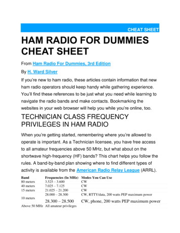
JS8 Activity All bands, 24-hours 40 meters most active, then 20 meters
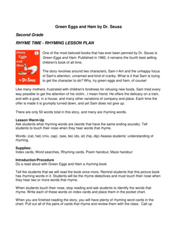
30 Meter JS8 Activity 24-hours Not a whole lot of activity, but still useful
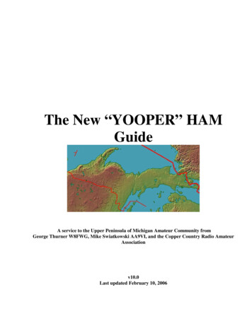
30 Meter WSPR Activity 24-hours We can see that propagation isn't the issue
Building a JS8 Gateway Station More 24/7 Stations! TX/RX is great, but RX-only is still useful Goal: Cheap, Easy, Good–Pick any two? 30 Meters (10.130 MHz USB) Cheap / Easy / (Good Enough) Rcv-Only I now have three 24/7 Cheap/Easy receive-onlygateway stations on 30 meters: Friday HarborWA, Occidental CA, and Anjala Finland
Receive-OnlyCheap / Easy / (Good Enough) RTL-SDR Blog Version 3: 22 Raspberry Pi 3B: 34 8G Micro SD Card: 4 RF Preamp: 11 10 MHz Front-End Filter: Homebrew, 5–Including preamp circuit: 7 USB Power Adaptor: 10 SMA Connectors, adaptors: 10 Total: 96–Not including antenna and coax
22 Software Defined ReceiverRTL-SDR BLOG v3 1PPM TCXO Software-switchable bias tee (for external preamp) Direct-sampling option for limited HF operation–28.8 MHz sample clock and non-quadrature outputmake external filtering mandatory, due to Nyquistaliasing above 14.4 MHz 8-bit A/D converter limits receiver dynamic range Actually works quite well for 30-meter (10 MHz) band are-Defined/dp/B0129EBDS2
SDR Sampling and Conversion
Spurious Responses due to Aliasing 28.8 MHz sample clock, 14.4 MHz Nyquist frequency Tuned to 10.0 MHz:– Tuned to 14.0 MHz:– Alias at 18.8 MHz, 38.8 MHz, 47.6 MHz (etc.)Alias at 14.8 MHz, 42.8 MHz, 43.6 MHz (etc.)RTL-SDR has no useful filtering at these frequencies
Front-End Filter 10 MHz bandpass filter with 18 MHz Notch 6dB loss due to design and component Q -70dB at first alias frequency Values and design may be different than shown
11.00 RF Preamp 100 Khz – 2 GHz, 30 dB gainWith jumper (or resistor) bridging output capacitor, RTLSDR can provide power via bias-T Preamp makes up for loss in front-end filter https://www.amazon.com/gp/product/B01N2NJSGV
DSP on Raspberry PiCSDR csdr is a command line tool to carry out DSPtasks for Software Defined Radio.It can be used to build simple signal processingflow graphs, right from the command line.https://github.com/simonyiszk/csdrNeed to play with time synchronization tocompensate for delay in DSP pipeline–Using “Chrony” for this
Configuration of RTL-SDR v3and DSP SSB Receiver#!/bin/bashif [ # -eq 1 ]thenfreq 1echo "frequency freq"rtl biast -b 1rtl sdr -s 1200000 -f python -c "print float( freq 100000)" -D 2 - csdr convert u8 f csdr shift addition cc 0.08333333333333 csdr fir decimate cc 25 0.05 HAMMING csdr bandpass fir fft cc 0 0.5 0.05 csdr realpart cf csdr agc ff csdr limit ff csdr convert f s16 aplay -v -r 48000 -f S16 LE elseecho "rtl-sdr-usb freq in Hz"fi
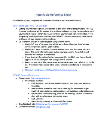
Receiver Performance80 Receiver tuned to 10.000 MHz,signal at 10.001 MHz giving1KHz beat noteNoise floor around 0.005 uV(useful with low-gain antenna)Using “Audacity” program forSNR analysisStill need to do strong-signaloverload (IMD) measurements70Sinnal/Noise Ratio dB 605040302010000.010.1Input in microvolts110100
Raspberry Pi JS8 Receive Gateway RPi running SDR software and JS8Call Reports received signals to pskreporter.info Forwards APRS messages to APRS-IS Uses 15% - 30% CPU cycles of Rpi 3 B– No heatsink requiredThat box on the left is a passive antenna splitter for A/B receiver testing
Paper-Clip Transmitting Antenna Receiver about 100 yards fromtransmitter. 1W output (if matched) Sending JS8 APRS email:APRS::EMAIL-2 :ME HELLO WORLD{02} “ME” is a shortcut for my emailaddressThis takes four JS8 frames to send(4 x 15 seconds)http://www.aprs-is.net/email.aspx
WB6CXC/FINRcv-only gateway in Finland Summer house in Finland,about 130km ENE of HelsinkiStation in upstairs utility closetIndoor antenna, 30m dipoletacked along ceiling trimMotorcycle battery backup
WB6CXC/FINRcv-only gateway in Finland
What Next? This gateway receiver design could be used below 10MHz with the appropriate front-end filter14 MHz is uncomfortably close to the 14.4 MHzNyquist frequency, would require a very fancy antialiasing filter18 MHz and 21 MHz operation should be practical, willhave sideband inversion (which can be fixed in thedemodulation software)A full transceiver design will probably not use a SDRreceiver, but instead a use hybrid analog / digitalapproach
Gateway Transceiver Receiver–Using “Tayloe Quadrature Sampling Mixer”–Analog low-pass filters with matched gain and delay–Two-channel A-D Converter–Software SSB demodulation similar to SDRgatewayTransmitter–Direct digital generation of 8-FSK JS8 signal–10W Class-E power amplifier, filtersA single clock generator chip can provide receiver andtransmitter clocks
Links http://js8call.com/ an-rtl-sdr-v3-and-raspberry-pi-3/ https://github.com/simonyiszk/csdr http://www.aprs-is.net/email.aspx are-Defined/dp/B0129EBDS2 https://www.amazon.com/gp/product/B01N2NJSGV
JS8 and JS8Call--Telemetry and Messaging--A JS8 to APRS Gateway ReceiverPaul Elliott / WB6CXCIn my previous presentation I mentioned the telemetrydrift-buoy I wanted to design and set free to roam theoceans of the world (and I still want to!) The buoywill have a low-power ( 10W) transmitter, sendingdata in the HF ham bands, probably 30 meters (10MHz.)In order for this to work, there needs to be a network ofreceivers that will pick up these transmissions andforward the data back to me, or at least to a placewhere it can be retrieved.
HF Telemetry Drift-buoy project needs a good way to transmit data to shore-basedserver.40 meters, 30 meters, and 20 meters are appropriate bands forworldwide paths.30m HF APRS has necessary features, but coding is far fromoptimum for error-prone weak-signal conditions.HF WSPR has good low-level characteristics and a good worldwidereceiving / reporting infrastructure. It is being used for sometelemetry but with a very limited and inflexible data format.FT8 has good low-level characteristics but a poor receiving / reportinginfrastructure. It also has very limited data capability.JS8Call is a new mode, derived from FT8–It includes Forward Error Correction and is optimized for weaksignal conditions.)–It provides a flexible data format and APRS interface.HF APRS, and WSPR were possible candidates, buteach had serious drawbacks.JS8 / JS8-Call has now come on the scene in a bigway, and looks like a winner.
JS8Call Created by Jordan Sherer / KN4CRDRuns on Windows, Mac OSX, Raspberry Pi, DesktoplinuxThe program is now in general release, seewww.js8call.com
JS8Call JS8Call was previously named FT8Call. Proposed July 2017, first program release July 2018 JS8Call uses a custom FT8 modulation called JS8 (JordanSherer designed 8-FSK modulation). This is the base RFtransport.JS8Call has a “directed calling” protocol laid on top of thebase RF transport to support free-form and directedmessage passing. Uses a keyboard messaging style interface. Provides API for remote and programmatic interface. Supports messaging to APRS–Position report, telemetry (etc), text msg, email.While JS8 modulation and coding is very similar toFT8, the two modes are not compatible. This is bydesign, since FT8 is built around fixed fields,designed for “contest style” QSOs, where a minimumset of standardized fields can be carried over asingle 15-second frame.JS8 instead provides a few fixed fields, but the bulk ofthe message space is available for free-format text,and allows multiple frames to be chained in order tosend messages of an arbitrary size.Using JS8 to send APRS email:@ALLCALL APRS::EMAIL-2 :ME msg body{xx}Fixed-length fields are used for APRS header
JS8Call Features Lots of good features for actual real-time freeform QSOs and general communications.Has mailbox capability so messages can bestored and automatically delivered.Messages can be relayed from station to station.Stations can be queried for their “heard” list,making relay routes easier to manage.No automatic routing (yet)Periodic “Heartbeat” transmissions, and autoACKs help provide network status information.– Of course you can always just call CQ and talk (type)to each other. Most of the JS8 activity is just this.
JS8Call Suitability JS8Call was created for human keyboard-keyboardcontacts, but it also has the necessary fundamentalcharacteristics to provide a reliable method for low-speeddigital communications of arbitrary data.But can it provide a receiving infrastructure? Will it witheron the vine as many previous digital modes have?FT8 is the most popular HF digital mode in use now, and itappears that many FT8 users are trying JS8. More than10,000 hams have downloaded the latest version of theJS8Call program.A mix of occasional operators and 24/7 gateway stationsshould provide good coverage. Not all operators will berelaying APRS, but some will.JS8-Call uses built-in Huffman compression for plainupper-case text, optimized for standard English letterfrequency as used in ham QSOs. There is alsosome sort of “phrase” compression – the details areunclear (actually, it's all revealed in the public-domaincode, I just haven't studied it.)The Huffman compression means that random data(such as telemetry values) will have to be mappedinto the 44-character Huffman table, resulting in aslight expansion rather than compression. Mappingrandom data into the first 38 table values looks to beoptimum, about an 8% expansion.Huffman compression uses fewer bits for morecommonly used characters. Much like Morse code.
JS8 Activity All bands, 24-hours 40 meters most active, then 20 metersLooking at www.pskreporter.info, we can see a recentday's worth of JS8 activity. Not all stations report topskreporter, but many do.I don't know how many also forward to APRS, but Iassume it's a small percentage since few use thisservice and a passcode is needed to do this. Thepasscode is easy to get, but it is still an additionalstepThe APRS passcode does not provide for security orauthentication. Other means are required for this.For telemetry and remote command, some methodof authentication should used.
30 Meter JS8 Activity 24-hours Not a whole lot of activity, but still useful
30 Meter WSPR Activity 24-hours We can see that propagation isn't the issue
Building a JS8 Gateway Station More 24/7 Stations! TX/RX is great, but RX-only is still useful Goal: Cheap, Easy, Good–Pick any two? 30 Meters (10.130 MHz USB) Cheap / Easy / (Good Enough) Rcv-Only I now have three 24/7 Cheap/Easy receive-onlygateway stations on 30 meters: Friday HarborWA, Occidental CA, and Anjala FinlandSo having more JS8 30-meter activity would be good.For my telemetry needs, having more receivers thatgateway to APRS is the big thing, but without peopletransmitting, few will put up receivers.A full gateway transceiver would be great, and it's easyto put one together using a ham transceiver and acomputer. But few people want to tie up their mainham rig for a 24/7 gateway.How to build a gateway that could be put into 24/7service? Here I describe an inexpensive SDRreceiver solution.A low-cost full transceiver design is also slowly beingdeveloped.
Receive-OnlyCheap / Easy / (Good Enough) RTL-SDR Blog Version 3: 22 Raspberry Pi 3B: 34 8G Micro SD Card: 4 RF Preamp: 11 10 MHz Front-End Filter: Homebrew, 5–Including preamp circuit: 7 USB Power Adaptor: 10 SMA Connectors, adaptors: 10 Total: 96–Not including antenna and coaxThere are better-performing SDR receivers out there(SDRPlay, Funcube, others), but these cost 100. Iwanted to see if the much cheaper RTL-SDR unitmight work acceptably.As with my Raspberry Pi WSPR transmitter, theantenna is perhaps the most expensive part of theproject. Fortunately, I have hundreds of feet of old#10 wire and coax, and a box of connectors. Andtrees.
22 Software Defined ReceiverRTL-SDR BLOG v3 1PPM TCXO Software-switchable bias tee (for external preamp) Direct-sampling option for limited HF operation–28.8 MHz sample clock and non-quadrature outputmake external filtering mandatory, due to Nyquistaliasing above 14.4 MHz 8-bit A/D converter limits receiver dynamic range Actually works quite well for 30-meter (10 MHz) band are-Defined/dp/B0129EBDS2
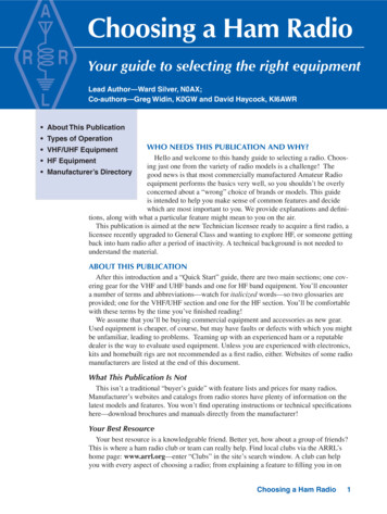
SDR Sampling and ConversionThis is the analog to digital converter and postconversion processing inside the back-end chip usedin the RTL-SDR (and most other SDRs). There isalso a front-end down-converter in these SDRs, butin the direct-sampling mode this downconverter isbypassed and the RF is routed directly to the A/Dconverter, which samples the input at 28.8 MHz.The converter output is re-sampled by a quadraturemixer, and the I/Q paths are further filtered. They arethen further down-sampled, filtered, and sent to theUSB interface. USB data rate is set to 1.2Mbytes/second.The 28.8 MHz sampling gives rise to spuriousresponses (Nyquist)
Spurious Responses due to Aliasing 28.8 MHz sample clock, 14.4 MHz Nyquist frequency Tuned to 10.0 MHz:– Tuned to 14.0 MHz:– Alias at 18.8 MHz, 38.8 MHz, 47.6 MHz (etc.)Alias at 14.8 MHz, 42.8 MHz, 43.6 MHz (etc.)RTL-SDR has no useful filtering at these frequenciesAlias frequencies are at (Fs * x) /- Ftune, x 1,2,3,.Fs sample clock frequencyFtune frequency receiver is tuned toYou can also use one of these alias frequencies as thedesired signal – this is called “undersampling”
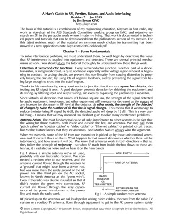
Front-End Filter 10 MHz bandpass filter with 18 MHz Notch 6dB loss due to design and component Q -70dB at first alias frequency Values and design may be different than shownTo reduce potential spurious responses, I built a frontend filter. I decided to give it a bandpass centered at10.1 MHz, with a sharp null at the first image of 18.8MHz. Given the fairly low dynamic range of the 8-bitA-D converter in the SDR, it seemed a good idea toat least somewhat filter out the lower frequencies aswell.Due to my construction techniques, and possiblecomponent resonances, the filter also showed apronounced null at 25 MHz. It wasn't due to the chipinductors; changing these to hand-wound toroidsdidn't change a thing. No harm done, but the higherfrequency rejection probably suffers because of this.The filter response plot may be from a design with onemore section. I tried a lot of filter designs.
11.00 RF Preamp 100 Khz – 2 GHz, 30 dB gainWith jumper (or resistor) bridging output capacitor, RTLSDR can provide power via bias-T Preamp makes up for loss in front-end filter https://www.amazon.com/gp/product/B01N2NJSGVThis is a Chinese board with a single Darlington-pairpreamp. I jumpered the output capacitor so the SDRbias-t could directly power the preamp. Dependingon the specific preamp used, a bypassed seriesresistor may be needed for bias-t powering.The preamp could easily be included in the filter circuit.Parts-cost: a couple of dollars, more than offset bythe fewer connectors required.
DSP on Raspberry PiCSDR csdr is a command line tool to carry out DSPtasks for Software Defined Radio.It can be used to build simple signal processingflow graphs, right from the command line.https://github.com/simonyiszk/csdrNeed to play with time synchronization tocompensate for delay in DSP pipeline–Using “Chrony” for this
Configuration of RTL-SDR v3and DSP SSB Receiver#!/bin/bashif [ # -eq 1 ]thenfreq 1echo "frequency freq"rtl biast -b 1rtl sdr -s 1200000 -f python -c "print float( freq 100000)" -D 2 - csdr convert u8 f csdr shift addition cc 0.08333333333333 csdr fir decimate cc 25 0.05 HAMMING csdr bandpass fir fft cc 0 0.5 0.05 csdr realpart cf csdr agc ff csdr limit ff csdr convert f s16 aplay -v -r 48000 -f S16 LE elseecho "rtl-sdr-usb freq in Hz"fiThis is largely taken from a tutorial on the tting-up-a-low-cost-qrp-ft8-jt9The design in the tutorial used “ncat” to send the SDRoutput to multiple demodulating applications. Isimplified it for single-channel use. Also, I haddropout problems with the audio piping usingPulseaudio. Instead, I use “aplay”. I also narrowedthe digital bandpass filter of the audio SSBdemodulator, giving it a 5 Khz cutoff.
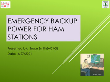
Receiver Performance80 Receiver tuned to 10.000 MHz,signal at 10.001 MHz giving1KHz beat noteNoise floor around 0.005 uV(useful with low-gain antenna)Using “Audacity” program forSNR analysisStill need to do strong-signaloverload (IMD) measurements70Sinnal/Noise Ratio dB 605040302010000.010.1110100Input in microvoltsWhile this sensitivity sounds amazingly good, it's stillfar from the fundamental limits of a 50-Ohm resistorat room-temperature. Still, perhaps I don't reallyneed the preamp. Early tests made me think theSDR was a bit “deaf”, but I should re-test this toverify. Excess gain does no good, and can causeoverload problems.I really want a “SNR” program so I can see real-timeresults, rather than sample the signal with Audacityand then use the FFT capability to see what I got.I also want a dual-signal source for overloadmeasurements. Shouldn't be too hard to puttogether.
Raspberry Pi JS8 Receive Gateway RPi running SDR software and JS8Call Reports received signals to pskreporter.info Forwards APRS messages to APRS-IS Uses 15% - 30% CPU cycles of Rpi 3 B– No heatsink requiredThat box on the left is a passive antenna splitter for A/B receiver testingWith a Power Over Ethernet adaptor and aweatherproof case, this entire gateway could belocated outside at the antenna, fed by an ethernetcable.For receive-only operation, a short untuned antennamight be sufficient.Some sort of transient protection on the RF andEthernet connections would be a good idea.Using “RealVNC server” on the RPi (included in theRaspbian image), and “RealVNC Client” on theremote computers. No monitor or keyboard neededat the Rpi. Monitor and control from anywhere. Upto five servers for free.
Paper-Clip Transmitting Antenna Receiver about 100 yards fromtransmitter. 1W output (if matched) Sending JS8 APRS email:APRS::EMAIL-2 :ME HELLO WORLD{02} “ME” is a shortcut for my emailaddressThis takes four JS8 frames to send(4 x 15 seconds)http://www.aprs-is.net/email.aspxOver the air testing of the gateway, using JS8Call on aWin10 PC, connected to an ICOM IC7200 or IC7300transceiver, with power dialed down to minimum, intoa mistuned antenna, or using paper-clip antenna.Gateway receiver has 10m dipole at a small distancefrom transceiver antenna.Also used antenna feeding a splitter, gateway . RPi onone port, Icom / Win computer on other. Ran bothreceivers for an hour, compared log results.Gateway did as well as Icom.Some interesting differences in SNR reports, Icombetter with strong signals, SDR better with weakones. Each of my three receiver locations are in aquiet RF environment.
WB6CXC/FINRcv-only gateway in Finland Summer house in Finland,about 130km ENE of HelsinkiStation in upstairs utility closetIndoor antenna, 30m dipoletacked along ceiling trimMotorcycle battery backupInstalled gateway in Finland on May 8, 2019. Probablynot a good spot for receiving a Pacific Ocean buoysignal, but I wanted to see how it worked anyway,and somebody might find it useful.Antenna snakes back and forth, tacked up so it won'tannoy my wife too much.I had trouble with USB power to RPi, discovered thatnot all micro-USB cables and power adaptors arecreated equal. Found some that work, but eventuallyreplaced plug-in power adaptor with motorcyclebattery / charger / 12V USB adaptor.
WB6CXC/FINRcv-only gateway in FinlandReceiver shows up in pskreporter, first stationsreceived were in Italy and RomaniaI can monitor and control this station from anywhere inthe world using VNC and the internet.“WB6CXC/FIN” is not a real callsign, just an arbitrarystation identifier for pskreporter and APRS. This isnot a transmitter so no official callsign or reciprocallicense arrangement is needed.
What Next? This gateway receiver design could be used below 10MHz with the appropriate front-end filter14 MHz is uncomfortably close to the 14.4 MHzNyquist frequency, would require a very fancy antialiasing filter18 MHz and 21 MHz operation should be practical, willhave sideband inversion (which can be fixed in thedemodulation software)A full transceiver design will probably not use a SDRreceiver, but instead a use hybrid analog / digitalapproachFor an extra 100, a better SDR would allow operationover the full range of ham bands.The direct digital FSK synthesis method is probably theleast expensive approach for QRP transmitterdesign. Some harmonic filtering is required, but ifthe synthesizer divider values are chosen carefullythe signals are otherwise clean enough.The Si5351 clock synth chip has three outputs, oneused for the transmitter, and the remaining two usedin the receiver circuit. This leads to an inexpensivetransceiver with decent performance.
Gateway Transceiver Receiver–Using “Tayloe Quadrature Sampling Mixer”–Analog low-pass filters with matched gain and delay–Two-channel A-D Converter–Software SSB demodulation similar to SDRgatewayTransmitter–Direct digital generation of 8-FSK JS8 signal–10W Class-E power amplifier, filtersA single clock generator chip can provide receiver andtransmitter clocksThe Tayloe mixer is a high dynamic-range zero-IF(direct conversion) design, using analogtransmission gates driven by quadrature clocks Ithas analog quadrature outputs (I/Q) which can beconverted to USB or LSB outputs using analog ordigital mixing techniques. This design would usedigital methods. (Tayloe doesn't have to be zero-IF,but usually is.)The chosen A-D converter samples at 192 Khz, somatched analog filters are required at the input toeliminate aliasing.Power Over Ethernet may have difficulty feeding a10W transmitter.
Links http://js8call.com/ an-rtl-sdr-v3-and-raspberry-pi-3/ https://github.com/simonyiszk/csdr http://www.aprs-is.net/email.aspx are-Defined/dp/B0129EBDS2 https://www.amazon.com/gp/product/B01N2NJSGV
22 Software Defined Receiver RTL-SDR BLOG v3 1PPM TCXO Software-switchable bias tee (for external preamp) Direct-sampling option for limited HF operation – 28.8 MHz sample clock and non-quadrature output make external filtering mandatory, due to Nyquist aliasing above 14.4 MHz 8-bit A/D converter limits receiv