Transcription
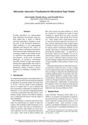
APPENDIXEHierarchical ModelIn the network model, the data are represented by collections of records andrelationships between data are represented by links. This structure holds for thehierarchical model as well. The only difference is that, in the hierarchical model,records are organized as collections of trees, rather than as arbitrary graphs.In this chapter we illustrate our concepts using a bank enterprise with theschema shown in Figure 2.15.E.1Basic ConceptsA hierarchical database consists of a collection of records that are connected toeach other through links. A record is similar to a record in the network model.Each record is a collection of fields (attributes), each of which contains only onedata value. A link is an association between precisely two records. Thus, a linkhere is similar to a link in the network model.Consider a database that represents a customer-account relationship in a banking system. There are two record types: customer and account. The customerrecord type can be defined in the same manner as in Appendix A. It consistsof three fields: customer name, customer street, and customer city. Similarly, the account record consists of two fields: account number and balance.A sample database appears in Figure E.1. It shows that customer Hayes hasaccount A-102, customer Johnson has accounts A-101 and A-201, and customerTurner has account A-305.Note that the set of all customer and account records is organized in the formof a rooted tree, where the root of the tree is a dummy node. As we shall see, ahierarchical database is a collection of such rooted trees, and hence forms a forest.We shall refer to each such rooted tree as a database tree.The content of a particular record may have to be replicated in several differentlocations. For example, in our customer-account banking system, an accountmay belong to several customers. The information pertaining to that account,or the information pertaining to the various customers to which that accountmay belong, will have to be replicated. This replication may occur either in the1
2Appendix EHierarchical ModelFigure E.1 Sample database.same database tree or in several different trees. Record replication has two majordrawbacks:1. Data inconsistency may result when updating takes place.2. Waste of space is unavoidable.We shall deal with this issue in Section E.5 by introducing the concept of a virtualrecord.E.2Tree-Structure DiagramsA tree-structure diagram is the schema for a hierarchical database. Such a diagramconsists of two basic components:1. Boxes, which correspond to record types2. Lines, which correspond to linksA tree-structure diagram serves the same purpose as an entity–relationship (E-R)diagram; namely, it specifies the overall logical structure of the database. A treestructure diagram is similar to a data-structure diagram in the network model.The main difference is that, in the latter, record types are organized in the form ofan arbitrary graph, whereas in the former, record types are organized in the formof a rooted tree.We have to be more precise about what a rooted tree is. First, there can be nocycles in the underlying graph. Second, there is a record type that is designated asthe root of the tree. The relationships formed in the tree-structure diagram mustbe such that only one-to-many or one-to-one relationships exist between a parentand a child. The general form of a tree-structure diagram appears in Figure E.2.Note that the arrows are pointing from children to parents. A parent may have anarrow pointing to a child, but a child must have an arrow pointing to its parent.The database schema is represented as a collection of tree-structure diagrams.For each such diagram, there exists one single instance of a database tree. The rootof this tree is a dummy node. The children of the dummy node are instances of the
E.2 Tree-Structure Diagrams3Figure E.2 General structure of a tree-structure diagram.root record type in the tree-structure diagram. Each record instance may, in turn,have several children, which are instances of various record types, as specified inthe corresponding tree-structure diagram.To understand how tree-structure diagrams are formed, we shall show how totransform E-R diagrams to their corresponding tree-structure diagrams. We firstshow how to apply such transformations to single relationships. We then explainhow to ensure that the resulting diagrams are in the form of rooted trees.E.2.1Single RelationshipsConsider the E-R diagram of Figure E.3a; it consists of the two entity sets customerand account related through a binary, one-to-many relationship depositor, withno descriptive attributes. This diagram specifies that a customer can have severalaccounts, but an account can belong to only one customer. The corresponding treestructure diagram appears in Figure E.3b. The record type customer corresponds toFigure E.3 E-R diagram and its corresponding tree-structure diagram.
4Appendix EHierarchical ModelFigure E.4 Tree-structure diagram with one-to-one relationship.the entity set customer. It includes three fields: customer name, customer street, andcustomer city. Similarly, account is the record type corresponding to the entity setaccount. It includes two fields: account number and balance. Finally, the relationshipdepositor has been replaced with the link depositor, with an arrow pointing tocustomer record type.An instance of a database corresponding to the described schema may thuscontain a number of customer records linked to a number of account records, asin Figure E.1. Since the relationship is one to many from customer to account,a customer can have more than one account, as does Johnson, who has bothaccounts A-101 and A-201. An account, however, cannot belong to more than onecustomer; none do in the sample database.If the relationship depositor is one to one, then the link depositor has twoarrows: one pointing to account record type, and one pointing to customer recordtype (Figure E.4). A sample database corresponding to this schema appears inFigure E.5. Since the relationship is one to one, an account can be owned byprecisely one customer, and a customer can have only one account, as is indeedthe case in the sample database.If the relationship depositor is many to many (see Figure E.6a), then the transformation from an E-R diagram to a tree-structure diagram is more complicated.Only one-to-many and one-to-one relationships can be directly represented in thehierarchical model.There are many different ways to transform this E-R diagram to a tree-structurediagram. All these diagrams, however, share the property that the underlyingdatabase tree (or trees) will have replicated records.Figure E.5 Sample database corresponding to diagram of Figure E.4.
E.2 Tree-Structure Diagrams5Figure E.6 E-R diagram and its corresponding tree-structure diagrams.The decision regarding which transformation should be used depends onmany factors, including The type of queries expected on the database The degree to which the overall database schema being modeled fits the givenE-R diagramWe shall present a transformation that is as general as possible. That is, all otherpossible transformations are a special case of this one transformation.To transform the E-R diagram of Figure E.6a into a tree-structure diagram, wetake these steps:1. Create two separate tree-structure diagrams, T1 and T2 , each of which hasthe customer and account record types. In tree T1 , customer is the root; in treeT2 , account is the root.2. Create the following two links: depositor, a many-to-one link from account record type to customer recordtype, in T1 account customer, a many-to-one link from customer record type to account record type, in T2The resulting tree-structure diagrams appear in Figure E.6b. The presence of twodiagrams (1) permits customers who do not participate in the depositor relationship as well as accounts that do not participate in the depositor relationship, and(2) permits efficient access to account information for a given customer as well ascustomer information for a given account.
6Appendix EHierarchical ModelFigure E.7 Sample database corresponding to diagram of Figure E.6b.A sample database corresponding to the tree-structure diagram of Figure E.6bappears in Figure E.7. There are two database trees. The first tree (Figure E.7a)corresponds to the tree-structure diagram T1 ; the second tree (Figure E.7b) corresponds to the tree-structure diagram T2 . As we can see, all customer and accountrecords are replicated in both database trees. In addition, account record A-201 appears twice in the first tree, whereas customer records Johnson and Smith appeartwice in the second tree.If a relationship also includes a descriptive attribute, the transformation froman E-R diagram to a tree-structure diagram is more complicated. A link cannotcontain any data value. In this case, a new record type needs to be created, and theappropriate links need to be established. The manner in which links are formeddepends on the way the relationship depositor is defined.Consider the E-R diagram of Figure E.3a. Suppose that we add the attributeaccess date to the relationship depositor, to denote the most recent date on whicha customer accessed the account. This newly derived E-R diagram appears inFigure E.8a. To transform this diagram into a tree-structure diagram, we must1. Create a new record type access date with a single field.2. Create the following two links:
E.2 Tree-Structure Diagrams7Figure E.8 E-R diagram and its corresponding tree-structure diagram. customer date, a many-to-one link from access date record type to customerrecord type date account, a many-to-one link from account record type to access daterecord typeFigure E.9 Sample database corresponding to diagram of Figure E.8b.
8Appendix EHierarchical ModelFigure E.10 Tree-structure diagram with many-to-many relationships.The resulting tree-structure diagram is illustrated in Figure E.8b.An instance corresponding to the described schema appears in Figure E.9. Itshows that: Hayes has account A-102, which was last accessed on 10 June 2009. Johnson has two accounts: A-101, which was last accessed on 24 May 2009,and A-201, which was last accessed on 17 June 2009.Figure E.11 Sample database corresponding to diagram of Figure E.10.
E.2 Tree-Structure Diagrams9 Turner has account A-305, which was last accessed on 10 June 2009.Note that two different accounts can be accessed on the same date, as wereaccounts A-102 and A-305. These accounts belong to two different customers, sothe access date record must be replicated to preserve the hierarchy.If the relationship depositor were one to one with the attribute date, thenthe transformation algorithm would be similar to the one described. The onlydifference would be that the two links customer date and date account would beone-to-one links.Assume that the relationship depositor is many to many with the attributeaccess date; here again, we can choose among a number of alternative transformations. We shall use the most general transformation; it is similar to the oneapplied to the case where the relationship depositor has no descriptive attribute.The record types customer, account, and access date need to be replicated, and twoseparate tree-structure diagrams must be created, as in Figure E.10. A sampledatabase corresponding to this schema is in Figure E.11.Until now, we have considered only binary relationships. We shift our attention here to general relationships. The transformation of E-R diagrams corresponding to general relationships into tree-structure diagrams is complicated.Figure E.12 E-R diagram and its corresponding tree-structure diagrams.
10Appendix EHierarchical ModelRather than present a general transformation algorithm, we present a single example to illustrate the overall strategy that you can apply to deal with such atransformation.Consider the E-R diagram of Figure E.12a, which consists of the three entitysets customer, account, and branch, related through the general relationship setCAB with no descriptive attribute.There are many different ways to transform this E-R diagram into a treestructure diagram. Again, all share the property that the underlying database tree(or trees) will have replicated records. The most straightforward transformationis to create two tree-structure diagrams, as shown in Figure E.12b.An instance of the database corresponding to this schema is illustrated in Figure E.13. It shows that Hayes has account A-102 in the Perryridge branch; Johnsonhas accounts A-101 and A-201 in the Downtown and Perryridge branches, respectively; and Smith has accounts A-201 and A-215 in the Perryridge and Mianusbranches, respectively.We can extend the preceding transformation algorithm in a straightforwardmanner to deal with relationships that span more than three entity sets. Wesimply replicate the various record types, and generate as many tree-structureFigure E.13 Sample database corresponding to diagram of Figure E.12b.
E.2 Tree-Structure Diagrams11Figure E.14 E-R diagram and its transformation.diagrams as necessary. We can extend this approach, in turn, to deal with ageneral relationship that has descriptive attributes. We need only to create a newrecord type with one field for each descriptive attribute, and then to insert thatrecord type in the appropriate location in the tree-structure diagram.E.2.2Several RelationshipsThe scheme that we have described to transform an E-R diagram to a tree-structurediagram ensures that, for each single relationship, the transformation will resultin diagrams that are of the form of rooted trees. Unfortunately, application ofsuch a transformation individually to each relationship in an E-R diagram doesnot necessarily result in diagrams that are rooted trees.Next, we shall discuss means for resolving the problem. The technique is tosplit the diagrams in question into several diagrams, each of which is a rooted tree.We present here two examples to illustrate the overall strategy that you can applyto deal with such transformations. (The large number of different possibilitieswould make it cumbersome to present a general transformation algorithm.)Consider the E-R diagram of Figure E.14a. By applying the transformationalgorithm in Section E.2.1 separately to the relationships account-branch and depositor, we obtain the diagram of Figure E.14b. This diagram is not a rooted tree,Figure E.15 Tree-structure diagram corresponding to Figure E.14a.
12Appendix EHierarchical ModelFigure E.16 E-R diagram and its transformation.since the only possible root can be the record type account, but this record type hasmany-to-one relationships with both its children, and that violates our definitionof a rooted tree (see Section E.2). To transform this diagram into one that is in theform of a rooted tree, we replicate the account record type, and create two separatetrees, as in Figure E.15. Note that each such tree is indeed a rooted tree. Thus, ingeneral, we can split such a diagram into several diagrams, each of which is arooted tree.Now consider the E-R diagram of Figure E.16a. By applying the transformationalgorithm described in Section E.2.1, we obtain the diagram in Figure E.16b. Thisdiagram is not in the form of a rooted tree, since it contains a cycle. To transformthe diagram to a tree-structure diagram, we replicate all three record types, andcreate two separate diagrams, as in Figure E.17. Note that each such diagram isindeed a rooted tree. Thus, in general, we can split such a diagram into severaldiagrams, each of which is a rooted tree.Figure E.17 Tree-structure diagram corresponding to Figure E.16a.
E.3 Data-Retrieval Facility13Figure E.18 Tree-structure diagram.E.3Data-Retrieval FacilityIn this section, we present a query language for hierarchical databases that isderived from DL/I, the data-manipulation language of IMS. To simplify the presentation, we shall deviate from the DL/I syntax, and shall use a simplified notation. Our language consists of commands that are embedded in a host language,Pascal. We shall use a simple example of a customer-account-branch schema. Thetree-structure diagram corresponding to this schema appears in Figure E.18. Itspecifies that a branch can have several customers, each of which can have severalaccounts. An account, however, may belong to only one customer, and a customercan belong to only one branch. An instance corresponding to this schema appearsin Figure E.19.Figure E.19 Sample database corresponding to Figure E.18.
14Appendix EE.3.1Hierarchical ModelProgram Work AreaEach application program executing in the system consists of a sequence of statements. Some of these statements are in Pascal; others are data-manipulationlanguage command statements. These statements access and manipulate databaseitems, as well as locally declared variables. For each such application program, thesystem maintains a program work area, which is a buffer storage area that containsthe following variables: Record templates. A record (in the Pascal sense) for each record type accessedby the application program Currency pointers. A set of pointers, one for each database tree, containingthe address of the record in that particular tree (regardless of type) mostrecently accessed by the application program Status flag. A variable set by the system to indicate to the application programthe outcome of the most recent database operation; we call this flag DB-statusand use the same convention as in the DBTG model to denote failure—namely,if DB-status 0, then the most recent operation succeeded.We reemphasize that a particular program work area is associated with preciselyone application program.For our branch-customer-account example, a particular program work areacontains the following: Templates. One record for each of three record types: branch record customer record account record Currency pointer. A pointer to the most recently accessed record of branch,customer, or account type Status. One status variableE.3.2The get CommandData are retrieved through the get command. The actions taken in response to aget are as follows:1. Locate a record in the database and set the currency pointer to it.2. Copy that record from the database to the appropriate program area template.
E.3 Data-Retrieval Facility15The get command must specify which of the database trees is to be searched. Forour example, we assume that the only database tree to be searched is the sampledatabase of Figure E.19; thus, we omit this specification in our queries.As an illustration of the general effect that the get command has on theprogram work area, consider the sample database of Figure E.19. Suppose thata get command is issued to locate the customer record belonging to Freeman.Once this command executes successfully, these changes occur in the state of theprogram work area: The currency pointer points now to the record of Freeman. The information pertaining to Freeman is copied into the customer recordwork-area template. DB-status is set to the value 0.To scan all records in a consistent manner, we must impose an ordering on therecords. The one commonly used is preorder. A preorder search starts at the root,and then searches the subtrees of the root from left to right, recursively. Thus, westart at the root, visit the leftmost child, visit its leftmost child, and so on, until wereach a leaf (childless) node. We then move back to the parent of the leaf and visitthe leftmost unvisited child. We proceed in this manner until we have visited theentire tree. For example, the preordered listing of the records in the database treeof Figure E.19 is:Parkview, Fleming, A-522, A-561, Freeman, A-533,Seashore, Boyd, A-409, A-622E.3.3Access within a Database TreeThere are two different get commands for locating records in a database tree. Thesimplest command has the formget first record type where condition The where clause is optional. The attached condition is a predicate that mayinvolve any record type that is either an ancestor of record type or the recordtype itself.The get command locates the first record (in preorder) of type record type in the database that satisfies the condition of the where clause. If the whereclause is omitted, then the command locates the first record of type recordtype . Once such a record is found, the currency pointer is set to point to thatrecord, and the content of the record is copied into the appropriate work-areatemplate. If no such record exists in the database tree, then the search fails, andthe variable DB-status is set to an appropriate error message.
16Appendix EHierarchical ModelAs an illustration, we construct the database query that prints the address ofcustomer Fleming:get first customerwhere customer.customer name "Fleming";print (customer.customer address);As another example, consider the query that prints an account belonging toFleming that has a balance greater than 10,000 (if one such exists).get first accountwhere customer.customer name "Fleming" and account.balance 10000;if DB-status 0 then print (account.account number);There may be several similar records in the database that we wish to retrieve.The get first command locates one of these. To locate the other database records,we can use the following command:get next record type where condition This command locates the next record (in preorder) that satisfies condition . Ifthe where clause is omitted, then the command locates the next record of type record type . Note that the system uses the currency pointer to determine whereto resume the search. As before, the currency pointer, the work-area template oftype record-type , and DB-status are affected.As an illustration, we construct the database query that prints the accountnumber of all the accounts that have a balance greater than 500.get first accountwhere account.balance 500;while DB-status 0 dobeginprint (account.account number);get next accountwhere account.balance 500;endWe have enclosed part of the query in a while loop, since we do not know inadvance how many such accounts exist. We exit from the loop when DB-status 0. This value indicates that the last get next operation failed, implying that wehave exhausted all account records with account.balance 500.The two previous get commands locate a database record of type recordtype within a particular database tree. There are, however, many circumstancesin which we wish to locate such a record within a particular subtree. That is,
E.4 Update Facility17we want to limit the search to one specific subtree, rather than search the entiredatabase tree. The root of the subtree in question is the most recent record thatwas located with either a get first or get next command. This record is known asthe current parent. There is only one current parent record per database tree. Theget command to locate a record within the subtree rooted at the current parenthas the formget next within parent record type where condition It locates the next record (in preorder) of type record type that satisfies condition and is in the subtree rooted at the current parent. If the whereclause is omitted, then the command locates the next record of type recordtype within the designated subtree. The system uses the currency pointer todetermine where to resume the search. As before, the currency pointer and thework-area template of type record type are affected. In this case, however,the DB-status is set to a nonzero value if no such record exists in the designatedsubtree, rather than if none exists in the entire tree. Note that a get next withinparent command will not modify the pointer to the current parent.To illustrate how this get command executes, we shall construct the querythat prints the total balance of all accounts belonging to Boyd:sum : 0;get first customerwhere customer.customer name "Boyd";get next within parent account;while DB-status 0 dobeginsum : sum account.balance;get next within parent account;endprint (sum);Note that we exit from the while loop and print out the value of sum only whenthe DB-status is set to a value not equal to 0. Such a value exists after the get nextwithin parent operation fails, indicating that we have exhausted all the accountswhose owner is customer Boyd.E.4Update FacilitySection E.3 described commands for querying the database. In this section, wedescribe the mechanisms available for updating information in the database. Theyallow insertion and deletion of records, as well as modification of the content ofexisting records.
18Appendix EE.4.1Hierarchical ModelCreation of New RecordsTo insert a record of type record type into the database, we must first setthe appropriate values in the corresponding record type work-area template.Once we set them, we add the new record to the database tree by executinginsert record type where condition If the where clause is included, the system searches the database tree (inpreorder) for a record that satisfies the condition in the where clause. Onceit finds such a record—say, X—it inserts the newly created record into the treeas the leftmost child of X. If the where clause is omitted, the system inserts therecord in the first position (in preorder) in the database tree where a record type record type can be inserted in accordance with the schema specified by thecorresponding tree-structure diagram.Consider the program for adding a new customer, Jackson, to the Seashorebranch:customer.customer name : "Jackson";customer.customer street : "Old Road";customer.customer city : "Queens";insert customerwhere branch.branch name "Seashore";The result of executing this program is the database tree of Figure E.20.As another example, consider the program for creating a new account numbered A-655 that belongs to customer “Jackson”:account.account number : "A-655";account.balance : 100;insert accountwhere customer.customer name "Jackson";The result of executing this program is the database tree of Figure E.21.E.4.2Modification of an Existing RecordTo modify an existing record of type record type , we must get that record intothe work-area template for record type , and change the desired fields in thattemplate. Then, we reflect the changes in the database by executingreplace
E.4 Update Facility19Figure E.20 New database tree.Note that the replace command does not have record type as an argument.The record that is affected is the one to which the currency pointer points, whichmust be the desired record.Figure E.21 New database tree.
20Appendix EHierarchical ModelThe DL/I language requires that, before a record can be modified, the getcommand must have the additional clause hold, so that the system is aware thata record is to be modified.As an example, consider the program to change the street address of Boyd toNorthview:get hold first customerwhere customer.customer name "Boyd";customer.customer street : "Northview";replace;Note that, in our example, we have only one record containing the address ofBoyd. If that were not the case, our program would have included a loop tosearch all Boyd records.E.4.3Deletion of a RecordTo delete a record of type record type , we must set the currency pointer topoint to that record. Then, we can delete that record by executingdeleteNote that, as in record modification, the get command must have the attributehold attached to it.As an illustration, consider the program to delete account A-561:get hold first accountwhere account.account number "A-561";delete;A delete operation deletes not only the record in question, but also the entiresubtree rooted by that record. Thus, to delete customer Boyd and all his accounts,we writeget hold first customerwhere customer.customer name "Boyd";delete;E.5Virtual RecordsWe have seen that, in the case of many-to-many relationships, record replicationis necessary to preserve the tree-structure organization of the database. Recordreplication has two major drawbacks:1. Data inconsistency may result when updating takes place.2. Waste of space is unavoidable.
E.5 Virtual Records21Figure E.22 Tree-structure diagram with virtual records.There are several ways to eliminate these drawbacks.To eliminate record replication, we need to relax our requirement that thelogical organization of data be constrained to a tree structure. We need to do thatcautiously, however, since otherwise we will end up with the network model.The solution is to introduce the concept of a virtual record. Such a recordcontains no data value; it does contain a logical pointer to a particular physicalrecord. Instead of replication, we keep a single copy of the physical record, andeverywhere else we keep virtual records containing a pointer to that physicalrecord.More specifically, we let R be a record type that is replicated in several treestructure diagrams—say, T1 , T2 , · · · , Tn . To eliminate replication, we create a newvirtual record type virtual-R, and replace R in each of the n 1 trees with a recordof type virtual-R.Figure E.23 Sample database corresponding to diagram of Figure E.22.
22Appendix EHierarchical ModelAs an example, consider the E-R diagram of Figure E.6a and its correspondingtree-structure diagram, which comprises two separate trees, each consisting ofboth customer and account record types (Figure E.6b).To eliminate data replication, we create two virtual record types: virtualcustomer and virtual account. We then replace record type account with recordtype virtual account in the first tree, and replace record type customer with recordtype virtual customer in the second tree. We also add a dashed line from virtualcustomer record to customer record, and a dashed line from virtual account recordto account record, to specify the association between a virtual record and itscorrespondi
Jun 10, 2009 · A hierarchical database consists of a collection of records that are connected to each other through links. A record is similar to a record in the network model. Each record is a collection of fields (attributes), each of which contains only one data value