Transcription
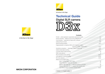
Progress ofNikon EUV Exposure ToolsNikon Corporation2nd Development DepartmentTakaharu Miura, Katsuhiko Murakami, Kazuaki Suzuki,Yoshiaki Kohama, Kenji Morita, Kazunari Hada, Yukiharu OhkuboPresentation ID: ET-062007 EUVL Symposium October 31, 2007; ET-06-MiuraSlide 1
Presentation Outline1. EUV tool development plan2. EUV1 specification and status3. Projection optics4. Plan for EUV25. Infrastructures6. Overall summary2007 EUVL Symposium October 31, 2007; ET-06-MiuraSlide 2
EUVL Tool Development PlanCal. Year200620072008ITRS2005DRAM ½ pFlash ½ pMPU C. Hole70 nm64 nm97 nmR&DprogramsASET (HiNA, small field)CollaborationNikonExposuretool65 nm57 nm84 nm57 nm51 nm73 nm200950 nm45 nm64 nm201045 nm40 nm56 nm201140 nm36 nm50 nm201235 nm32 nm44 nmEUVA (Wavefront sensor, Contamination control)SELETE (EUV Lithography and Mask Program)EUV1ForProcess developmentReviewEUV2For32nm productionEUV1 (Process Development Tool) is under system integration.2007 EUVL Symposium October 31, 2007; ET-06-MiuraSlide 3
EUV1 Tool SpecificationsEUV1: For 45nm hp node process development& 32nm hp node R&DSpecification ItemEUV126 x 33 mm2Field SizeNA and MagnificationResolution0.25, x1/4Dense line: 45 nm @hpIsolated line: 25 nm(Target 32 nm @hp)Flare10 %Overlaytarget 10 nm (3s)Wafer Size300 mmThroughput (10W & 5mJ/cm2)5-10 WPH2007 EUVL Symposium October 31, 2007; ET-06-MiuraSlide 4
EUV1 Tool Development StatusModuleModule Integration System OperationWe are hereReticle/WaferLoadersStatic exposuredata availablein FebruaryReticleStageWaferStage2007 EUVL Symposium October 31, 2007; ET-06-MiuraSlide 5
Light Source and IU StatusSource HeadBodySourceEUV1 and light source- Aligning optical axis and tuning withViolet light is visibleilluminator ongoing.light from a plasma- Light source IF poweristheissue.2007 EUVL Symposium October 31, 2007; ET-06-MiuraSlide 6
EUV1 IU Test Stand- Visible light measurement- EUV light measurementVisiblelightsourceVacuumchamberEUV lightsource(Contains FE1, FE2,Con1, Con2, Flat mirror)Side viewBack view2007 EUVL Symposium October 31, 2007; ET-06-MiuraSlide 7
Status of EUV1 Illumination Unit (IU) Visible light image on test stand Illumination uniformity on test stand (EUV light)2Uniformity Error (%)1 .510 .50- 0 .5-1Uniformity of /-0.5% was achieved.- 1 .5-2-60-40-200204060P o s it io n o n R e tic le ( m m )2007 EUVL Symposium October 31, 2007; ET-06-MiuraSlide 8
First light (visible light) on BodyPicture of arc-shaped field imaged on Waferwith visible light from IU through PO optics.EUV light on reticle plane confirmed.EUV light on wafer ongoing.2007 EUVL Symposium October 31, 2007; ET-06-MiuraSlide 9
Reflective Projection Optics DevelopmentKey technologies Metrology- High repeatability interferometers- Visible light wavefront metrology system- EUV wavefront metrology system Polishing- New polishing technology (IBF, EEM)- The state of the art for mirror polishing Coating- Multilayer coating process using magnetronsputtering Assemble and Adjustment- Ultra-precise position control2007 EUVL Symposium October 31, 2007; ET-06-MiuraSlide 10
EUV1 PO and production toolsSupported by NEDOSupported by NEDOSupported by NEDOSupported by NEDOMirror fabrication toolsEUV1ProjectionopticsOptical evaluation tools2007 EUVL Symposium October 31, 2007; ET-06-MiuraSlide 11
Wave front error improvement1st Proto-type(for EWMS)EUV1PO(in process)2nd Proto-type(for EUV1)EUV1PO(in process)EUV1PO(current)WFE (nmRMS)10.04.03.02.01.0Target0.02006 2H2007 1H2007 2HWave front error has been reduced drastically less than 1nm RMS.2007 EUVL Symposium October 31, 2007; ET-06-MiuraSlide 12
Wave front map of EUV1POExtremely small WFE below 1 nm RMSwas achieved in the ring field !λλWFE 0.6 nm RMS(average)2007 EUVL Symposium October 31, 2007; ET-06-MiuraSlide 13
MSFR improvement0.40HiNA#2MSFR .10EUV10.052000200220042006YEAR20082010Extremely small MSFR was achieved on all mirrors.2007 EUVL Symposium October 31, 2007; ET-06-MiuraSlide 14
Calculated PSF and flare estimationAiry disk PSF curvecalculated using WFERadius PSF (m-2)Kirk patternsize 2μmPSF curvecalculated using PSD10%Radius on wafer (m)Point spread function in the range of 1mm is dominated by flare.Estimated flare number is 10%.2007 EUVL Symposium October 31, 2007; ET-06-MiuraSlide 15
Short Summary on Optics1. Projection optics- Metrology, polishing and coating technologieswere developed and steadily improved.- Extremely small wavefront error of 0.6nm RMS wasachieved.2. Illumination optics- Fabrication process of fly’s eye mirrors which iskey device of illumination optics was established.- Evaluation of illumination optics using IU test standwas completed.- Illumination uniformity with EUV light on a reticleplane of less than /- 0.5% was confirmed.2007 EUVL Symposium October 31, 2007; ET-06-MiuraSlide 16
Short Summary on Light source and Tool1. Light source module- System test completed.Output power @ IF currently 2-3 W level.Further improvement works ongoing.- Docking with the tool completed.- Fine tuning with IU optics ongoing.3. System integration- Moduleintegration completed.- EUV light on reticle confirmed.- EUV light on wafer and preparation for staticexposure ongoing.- Static exposure scheduled by March/2008.Static exposure data available inFebruary/2008.2007 EUVL Symposium October 31, 2007; ET-06-MiuraSlide 17
EUV2 Tool Development PlanCal. Year200620072008ITRS2005DRAM ½ pFlash ½ pMPU C. Hole70 nm64 nm97 nmR&DprogramsASET (HiNA, small field)CollaborationNikonExposuretool65 nm57 nm84 nm57 nm51 nm73 nm200950 nm45 nm64 nm201045 nm40 nm56 nm201140 nm36 nm50 nm201235 nm32 nm44 nmEUVA (Wavefront sensor, Contamination control)SELETE (EUV Lithography and Mask Program)EUV1ForProcess developmentReviewEUV2For32nm production- Best available light sourceand infrastructure.2007 EUVL Symposium October 31, 2007; ET-06-MiuraSlide 18
Challenging items in EUV2 developmentImaging Performance Exchange of illuminationcondition Low aberration, low flare opticsReticle Strategy for library Carrier complied withSEMI standardOverlay Tool stabilityThroughput Rigid body for high throughput High speed & precisionvacuum compatible stage High power EUV sourceThermal management Heat rejection from mirrorsof illumination opticsImprovement of CoO Lifetime of EUV mirrors Downtime during maintenance2007 EUVL Symposium October 31, 2007; ET-06-MiuraSlide 19
Imaging Performance SimulationProcess window vs. illumination condition22nm L/SConv. 0.8Ann. 0.4/0.825nm H/SDipole 0.6/0.2Conv. 0.81000DOF (nm)DOF (nm)80060040020000246810Lambda: 13.5nm, NA: 0.25,CD error: /-10% of CD, Mask CD error: /-0.5nm,Mask contrast: 1:100, Flare: 7%*pattern densityQuad 0.6/0.23503002502001501005000246810Dose Error ( /-%)Dose Error ( /-%)ED-Tree DOF Conditions:Ann. 0.4/0.8NA0.25 Projection Optics:Useful for 22nm hp nodefor process development.2007 EUVL Symposium October 31, 2007; ET-06-MiuraSlide 20
Main Specification of EUV2Specification ItemEUV1EUV2 (Provisional)26 x 33 mm226 x 33 mm20.25, x1/40.25, x1/4ResolutionDense line: 45 nmIsolated line: 25 nm(Target 32 nm dense line)Dense line: 32nmIsolated line: 21nm(Target 22nm dense line)Wavefront0.7 nm rms0.5 nm rms10 %7%Target 10 nm (3s)7 nm (3s)Wafer Size300 mm300mmThroughput5-10 wph(10W IF, 5mJ/cm2)50 wph(50W IF, 5mJ/cm2)Field SizeNA and MagnificationFlareOverlay2007 EUVL Symposium October 31, 2007; ET-06-MiuraSlide 21
Contamination ControlContamination Control Strategy1. Anti-oxidation capping layer2. Carbon-film suppression and removal3. Resist outgassing- Proposal of outgassing rate of H2O and CxHy4. Experiment facilities- SR “Super-ALIS” in Atsugi (NTT) and SR Undulator“New SUBARU” in Himeji (Univ. of Hyogo)2007 EUVL Symposium October 31, 2007; ET-06-MiuraSlide 22
Difference between Pulsing & SR SourceNormalized Reflectance History1.2ReflectanceReflectance historyhistory byby pulsingpulsing sourcesourceReflectance [ ]1.11.0 EUV irradiation by inhouse solid-state targetsource High H2O pressure No OoB light with SPF0.9NoNo evidentevidentreflectancereflectance dropdrop0.80.7XPSXPS resultsresultsSRCSRPulsePositionDose [arb.]XPS [atomic %](Error 1%)SiDoOΔSiDoOdegree of 516.955.6%4.1%4.5%NoNo evidentevidentdifferencedifference ofofoxidationoxidation statestateNoNo significantsignificant differencedifference betweenbetween pulsingpulsing andand SRSR sourcesource2007 EUVL Symposium October 31, 2007; ET-06-MiuraSlide 23
Capping Layer: Screening & g didates:DurabilityTestNormalized Reflectance1.021.000.98Material AMaterial BSi-capOthers0.960.940200400600800Dose [J/mm2]1,0001,200- EUV irradiation to capping material candidates with intense undulatorwas performed under H2O vapor introduction.- Optimization of coating condition of the candidates is also ongoing.SomeSome ofof candidatescandidates showsshows nono significantsignificant degradationdegradation2007 EUVL Symposium October 31, 2007; ET-06-MiuraSlide 24
Reticle Protection* Dual Pod Concept by Canon and Nikon1. Reticle in Cassette(RC) inCarrier(RSP200).2. Cassette protects the reticle in loadlocks.3. Top cover stays with reticle during in-toolhandling.4. Reticle remains in RC in library to protectagainst vacuum accidents e (Reticle Cover)RSP2007 EUVL Symposium October 31, 2007; ET-06-MiuraSlide 25
Reticle Protection Development Status1. Nikon has been developing Dual Pod Concept forEUV reticle carrier standardization in cooperationwith Canon and Entegris.2. Nikon also has developed the reticle cover for EUV1tool.- The average added particles reported in SPIE 2006.“0 - 0.3 per cycle during 10 cycles”- The reticle cover for EUV1 tool manufactured.- Reticle handling trial on the tool has started.Reticle Carrier for EUV1 (Dual Pod)Outer PodInner Pod2007 EUVL Symposium October 31, 2007; ET-06-MiuraBottom CoverSlide 26
Overall Summary1. EUVL can be the main lithographytechnology after ArF immersion.2.Nikon is developing a full field exposure tool(EUV1) for 45nm hp process developmentand 32nm hp R&D.3. EUV2 (HVM) can be developed adopting thebest available EUV light source andinfrastructure.- Technology and business assessments in 2007.4.Performance of light source andinfrastructure such as EUV reticle, resist, etc.is steadily improving.2007 EUVL Symposium October 31, 2007; ET-06-MiuraSlide 27
Acknowledgements1. A part of this work was conducted under EUVAprojects. EUVA projects have been supported by NewEnergy and Industrial Technology DevelopmentOrganization (NEDO).- Nikon gratefully acknowledges Japan Ministry ofEconomy, Trade and Industry (METI) and NEDO fortheir supports.2. Nikon also participate in Selete program andappreciate Selete members for their usefuldiscussion and advice.3. The work presented here is the result of team effortin both Nikon and partner companies.2007 EUVL Symposium October 31, 2007; ET-06-MiuraSlide 28
Polishing - New polishing technology (IBF, EEM) - The state of the art for mirror polishing Coating - Multilayer coating process using magnetron sputtering Assemble and Adjustment - Ultra-precise position control