Transcription
Computational Photography:Principles and PracticeHCI & Robotics(HCI 및 로봇응용공학)Ig-Jae Kim, Korea Institute of Science and Technology(한국과학기술연구원 김익재)Jaewon Kim, Korea Institute of Science and Technology(한국과학기술연구원 김재완)University of Science & Technology(과학기술연합대학원대학교)
PrefaceComputational Photography is a new research field emerging from the early 2000s, which isat the intersection of computer vision/graphics, digital camera, signal processing, appliedoptics, sensors and illumination techniques. People began focusing on this field to provide anew direction for challenging problems in traditional computer vision and graphics. Whileresearchers in such domains tried to solve problems in mainly computational methods,computational photography researchers attended to imaging methods as well ascomputational ones. As a result, they could find good solutions in challenging problems byvarious computations followed with optically or electronically manipulating a digital camera,capturing images with special lighting environment and so on.In this field researchers have been attempted to digitally capture the essence of visualinformation by exploiting the synergistic combination of task-specific optics, illumination,and sensors challenging traditional digital cameras’ limitations. Computational photographyhas broad applications in aesthetic and technical photography, 3D imaging, medical imaging,human-computer interaction, virtual/augmented reality and so on.This book is intended for readers who are interested in algorithmic and technical aspects ofcomputational photography researches. I sincerely hope this book becomes an excellent guideto lead readers to a new and amazing photography paradigm.This book was supported from University of Science and Technology's book writing supportprogram for being written.i
Contents1. Introduction2. Modern Optics2.1 Basic Components in Cameras2.2 Imaging with a Pinhole2.3 Lens2.4 Exposure2.5 Aperture2.6 ISO2.7 Complex Lens3. Light Field Photography3.1 Light Field Definition3.2 Generation of a Refocused Photo using Light Field Recoding3.3 Other Synthetic Effects using Light Field3.4 Light Field Microscopy3.5 Mask-based Light Field Camera4. Illumination Techniques in Computational Photography4.1 Multi-flash Camera4.2 Descattering Technique using Illumination4.3 Highlighted Depth-of-Field (DOF) Photographyii
5. Cameras for HCI5.1 Motion Capture5.1.1 Conventional Techniques5.1.2 Prakash: Lighting-Aware Motion Capture5.2 Bokode: Future Barcode6. Reconstruction Techniques6.1 Shield Fields6.2 Non-scanning CTiii
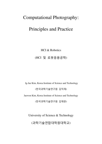
Chapter 1IntroductionSince the first camera, Daguerreotype (Figure 1.1(a)), was invented in 1839, there have beena lot of developments in terms of shape, components, functions and capturing method. Figure1.1 shows a good comparison reflecting such huge developments between the first and amodern camera. However, I would like to see the most significant changes have been createdin recent years through transition from a film camera to a digital camera. The transition,maybe more accurately a revolution, doesn’t simply mean the change of an image-acquisitionway. It has rapidly changed an imaging paradigm with new challenging issues as well as a lotof convenient functions. In spite of such huge changes, it’s ironical there is no significantchange in the shape itself as shown in figure 1.2.(a) Daguerreotype, 1839(b) Modern Camera, 2011 Figure 1.1 Comparison of the first and a modern camera 1
(a) Nikon F80 Film Camera(b) Nikon D50 Digital Camera Figure 1.2 Comparison of a film and a digital camera With the emergence of digital cameras, people easily and instantly acquire photos withouttime-consuming film development process which was a necessary process in filmphotography. However, such convenience brought negative matters as well. First of all,photographic quality was critical issue in early commercialized digital cameras due toinsufficient image resolution and poor light sensitivity in image sensors. Digital cameraresearchers have kept improving photographic quality to be comparable to film camera andfinally a film camera have become a historical device. However it’s still hard to say thatmodern digital camera’s quality is better than film camera’s in the aspect of image resolutionand dynamic range. Researchers are constantly working to improve digital camera’s qualityand implement more convenient functions, which are shared goals in computationalphotography research.Computational photography researchers have involved in more challenging issues to breaktraditional photography’s limitation. For example, digital refocusing technique controls DOF(Depth of Field) by software processing after shooting. Probably, everyone experienceddisappointment with ill-focused photos and found there is no practical way to recover wellfocused photos by traditional methods such as deblurring functions in Photoshop. Digitalrefocusing technique provides a good solution for such cases. Likewise, computationalphotography researches have been broadening the borders of photography making imaginary2
functions possible. In such stream, I convince modern cameras will be evolved to moreinnovative forms.Chapter 2Modern Optics2.1 Basic Components in CamerasLet’s imagine you are making a cheapest camera. What components are indispensable for thejob? First of all, you might need a device to record light such as film or CCD/CMOS, whichare analog and digital sensors, respectively. What’s next? Do you need a lens for a cheapestcamera? What will happen if you capture a photo without a lens as Figure 2.1? You will get aphoto anyway since your film or image sensor record light somehow. However, the photodoesn’t actually provide any visual information regarding the subject. If you are using adigital sensor, its pixels will record meaningless light intensity and you cannot recognize thesubject’s shape in the captured photo. What’s the reason for that? As shown in Figure 2.1 (a),every point on the subject’s surface reflects rays to all directions and they all are merged withrays coming from different subject points onto the film or image sensor. Therefore, it’simpossible to capture clear visible information of the subject only with a film or an imagesensor. Then, how can your cheapest camera capture the subject shape? You may need anoptical component to isolate rays coming from different subject points on a film or an imagesensor. Commercial cameras usually use lenses for this job but cheaper component is apinhole, which is a mere tiny hole passing incoming rays through it and blocking other raysreaching outer region of the hole. Your camera can successfully capture the subject’s shapewith a pinhole as shown in Figure 2.1 (b).3
Film/Image Sensor Figure 2.1 (a) Imaging without any optical components (b) Imaging with a pinhole 2.2 Imaging with a PinholeNow you may have a question why commercial cameras use a lens instead of a pinholealthough a pinhole is much cheaper. Main reason is that pinhole imaging loses significantamount of incoming rays generally causing a very dark photo compared with lens imagingunder the same exposure time. In Figure 2.1 (b), a single ray among a lot of rays reflectedfrom a subject point passes through an ideal pinhole while many rays pass through a lens.The amount of incoming rays onto a film/image sensor is directly proportional to the capturedphoto’s brightness.An ideal pinhole cannot be physically manufactured in real world and actual pinholes passthrough small portion of rays per each subject point. Figure 2.3 shows how the capturedphoto varies with pinhole diameter. Let’s start with imagining an extremely large pinhole.Your photo doesn’t give the subject’s shape with it since using such pinhole is just same withimaging by only a film/image sensor in Figure 2.1 (a). Now you use a pinhole in 2mm4
diameter then your photo would look like the top-left photo in Figure 2.3. The photo is stilltoo blurred to recognize the subject shape due to the interference between rays coming fromdifferent subject points. As pinhole diameter is reduced, the interference is reduced andcaptured photo’s sharpness is enhanced up to a certain level. In Figure 2.3, the middle-rightphoto taken with a 0.35mm diameter pinhole shows the best sharpness. If you use a muchsmaller pinhole than this, will you get a much sharper photo? The answer is no as shown inthe two bottom photos. They, taken with smaller diameter pinholes, show blurred again, andthe reason for that is diffraction phenomenon.(from Ramesh Raskar's lecture note) Figure 2.3 Captured photos with a pinhole according to its diameter Figure 2.4 shows water waves’ diffraction phenomenon and light shows similarcharacteristics when passing through a very tiny area. When light experiences diffraction, itdiverges at the exit of the area in inverse proportion to the area size. Thus, the bottom-rightcase with a 0.07mm diameter pinhole makes light more diverged than the bottom-left case5
with 0.15mm diameter pinhole, resulting in more blurred photo. Ideally, your pinholephotograph has the best sharpness at the slightly bigger size than causing diffraction.(from Fredo Durand's lecture note) Figure 2.4 Diffraction of water waves 2.3 LensAlthough we can get a sharp photo with a pinhole camera, it’s not applicable for acommercial product since a pinhole blocks most incoming light creating a very dark photo.Alternatively lens has been adopted in commercial cameras to overcome such pinhole’slimitation as well as isolate rays coming from different subject points. Figure 2.5 comparestwo photographs taken by a pinhole and a lens, respectively. You may notice that the twophotos’ brightness is similar but the pinhole photo at top was taken in 6 seconds exposuretime while the bottom photo using a lens was taken in 0.01 second. The bottom-right imageshows that much more rays coming from a single subject point can be transmitted to afilm/image sensor compared with pinhole imaging at the top-right image. The definition offocusing in lens optics is the ability to converge rays coming from a single subject spot intoan imaging spot. If you capture a photo with ill-focused lens, the ray convergence fails andthe interference between rays originated from different subject points happens producing ablurred photo.6
Let’s inspect how lens transmits rays. Figure 2.6 illustrates the way in which rays arerefracted by an ideal thin lens. ‘a’ ray enters to lens in parallel direction with the optical axismarked as a dotted line and is refracted toward the focal point of the lens. ‘b’ ray passingthrough the center of lens keep moving in same direction without being refracted. All rayscoming out from the object’s point, P, are gathered in the crossing point of the two rays, P .As an example, the third ray, ‘c’, coming out at an arbitrary angle arrives at the point, P called as “imaging point”. Now you can easily find out the location of the imaging point forany kind of lens given the focal point of lens by simply drawing two rays, one in paralleldirection with the optical axis and the other entering to the lens center. Figure 2.5 Comparison of photographs taken with pinhole and lens 7
oiaPbFocalPointcP’f Figure 2.6 A diagram for image formation with a lens Equation 2.1 explains a geometrical relation between focal point (f), object point distance (o)and imaging point distance (i) from lens.1 1 1 i o f Equation 2.1 There is another physical raw describing refraction in lens optics, which is Snell’s law inEquation 2.2. When a ray penetrates a certain object such as a lens in Figure 2.7, refractionoccurs at the entry point of the object. Refraction is a physical phenomenon to explain thechange of a ray’s propagating direction at entering from a medium to a different medium. InFigure 2.7, a ray enters to a lens at 1 incident angle and is refracted at 2 angle. The amountof refraction is related with media’s refractive indices in Equation 2.2, n1 and n2 for the firstand second medium’s refractive index, respectively. In the case that a ray penetrates a lens inair, like Figure 2.7, n1 and n2 indicate refractive indices of air and the lens.8
1 2 Figure 2.7 A diagram describing Snell’s raw n1sin 1 n2sin 2 Equation 2.2 I assume you may be familiar with camera’s zoom function. Have you been curious abouthow it works? When you are adjusting zoom level in your camera, actually you are changingthe focal length of lens in your camera. In photography, zoom is often called as FOV (Field ofView) which means the area of view captured in a camera. Wide FOV indicates that yourphoto contains large area’s visual information and vice versa. Figure 2.8 shows the relationbetween focal length and FOV. With a lens having short focal length in the figure, yourcamera gets an image in the boundary of the dotted lines. While it gets an image in theboundary of the solid lines with a lens having long focal length. Therefore, we can say thereis inverse proportional relation between focal length and FOV. Your camera lens should be setas long focal length to achieve a shallow FOV photo, in other words a zoom-in photo. Figure2.9 depicts the numerical relation between focal length and FOV in mm and degree,respectively with example photos. The wide FOV photo contains wide landscape scene whilethe small FOV photo does small area scene but in more detail.9
longfocallengthshortfocallengthFOV Figure 2.8 Focal length vs. FOV 24mmWide FOV50mm135mmSmall FOV(from Fredo Durand's lecture note) Figure 2.9 Focal length vs. FOV in measurements 10
2.4 ExposureOne of the most important factors in photo’s quality might be brightness. Usually, photo’sbrightness is controlled by two setting parameters, exposure time and aperture size, in acamera and an additional parameter, ISO, for a digital camera. Exposure time means theamount of time duration for which a film/sensor is exposed. You can imagine that longerexposure time would make your photo brighter than shorter exposure time and vice versa.Also, it’s straightforward to expect the effect in linear relation. For example, two times longerexposure time would make a photo two times brighter. Usually, exposure time is set infraction of a second such as 1/30, 1/60, 1/125, 1/250 and etc. Long exposure time is good toachieve a bright photo but may cause a side effect, motion blur. Motion blur is blur effectcreated in a photo due to the movement of a subject or a camera while exposing. The leftphoto in Figure 2.10 shows motion blur effect by the subject’s movement. Freezing motioneffect as shown in Figure 2.11 can be achieved with appropriate exposure time according tosubjects’ speed. Figure 2.10 Motion blurred photo (left) and sharp photo (right) 11
(from Fredo Durand's lecture note) Figure 2.11 Freezing motion effect in photos with appropriate exposure times 2.5 ApertureAperture indicates the diameter of lens opening, Figure 2.12 left, which controls the amountof light passing through lens. Lens aperture is usually expressed as a fraction of a focal lengthin F-number with Equation 2.3 formula (f, D and N indicate focal length, aperture diameterand F-number, respectively.) In the formula, F-number is inversely proportional to aperturediameter. For example given f/2 and f/4 in F-number with 50mm focal length, the aperturediameter is 25mm and 12.5mm, respectively. F-number is typically set by following valuesusing a mechanism called diaphragm in Figure 2.12 right:f/2.0, f/2.8, f/4, f/5.6, f/8, f/11, f/16, f/22, and f/32Figure 2.13 shows different aperture sizes shaped by diaphragm. Figure 2.12 Lens aperture (left) and diaphragm (right) 12
Equation 2.3 Figure 2.13 different aperture sizes controlled by diaphragm Aperture size is a critical factor to control photo’s brightness as exposure time. However, italso has an important function in photography, which is the control of DOF (Depth-of-Field).DOF is defined as a specific region where all objects are well focused. Figure 2.14 shows twophotographs for a same scene taken with different DOF settings. The left photo has anarrower DOF where only foreground man is well focused than the right photo where theboth foreground man and background building are well focused. Such change of DOF can beobtained by using different aperture size. The larger aperture is used, the narrower DOF isobtained. Accordingly, the left photo in Figure 2.14 was taken with the larger aperture thanthe right photo. In the left image of Figure 2.15 presenting the definition of DOF, ‘a’ locationgives the sharpest focus while ‘b’ and ‘b ’ locations do slight defocus creating not a point buta circular image for a point object in the bottom image. Such circular image is called as‘Circle of Confusion (COC)’ and the farthest distance from the sharpest focusing location,where COC is maximally acceptable as being focused, is defined as DOF. In the right photoof Figure 2.15, the top and bottom pencils mark DOF.13
(from Photography, London et al.) Figure 2.14 Photos with large aperture (left) and small aperture (right) b aabb(from Fredo Durand's lecture note) Figure 2.15 Definition of DOF (left) and a photo showing DOF (right) Now you learned aperture size is related with DOF. But what’s the mathematical relation?The amount of change in one parameter is inversely proportional to the amount of change inthe other as shown in Figure 2.16. In the figure, if the aperture is decreased by two times, thescene area contributing to COC is decreased by the same amount and thus DOF is doubled.Figure 2.17 and Figure 2.18 show the relation of focusing distance vs. DOF and focal lengthvs. DOF, respectively. The focusing distance is in proportional relation with DOF while focal14
length is vice versa as shown in the figures. Figure 2.16 Aperture size vs. DOF Figure 2.17 Focusing distance vs. DOF (left) and Focal length vs. DOF (right) In summary, DOF is proportional to focusing distance and inversely proportional to aperturesize and focal length in Equation 2.3.DOF Focusing DistanceAperture * Focal Length Equation 2.3 Until now, you learned important camera parameters, terms and their physical meanings andrelations with others. Basically you have a lot of setting options for those parameters when15
shooting your camera and you need to set the best values for your target scene. Figure 2.18shows photos taken with different aperture and exposure time values. As you see in the leftphoto, large F-number (small aperture size) is good for wide DOF and requires long exposuretime to achieve enough brightness in a photo creating motion-blur artifact. The right photowith small F-number (wide aperture size) and short exposure time is good for reducedmotion-blur artifact but background is out of focused due to reduced DOF. The middle photoshows trade-off between motion-blur artifact and DOF.(from Photography, London et al.) Figure 2.18 Photos captured with different settings of aperture and exposure time (Left to right setting values are (f/16, 1/8), (f/4, 1/125), and (f/2, 1/500) for F-number andexposure time, respectively.)16
2.6 ISOISO can be regarded as an electronic gain for a digital camera sensor such as CCD andCMOS. As the most electronics gains do, it amplifies the both image signal and noise level.ISO value linearly works for photo’s brightness and noise level. In Figure 2.19 the larger ISOvalue is applied, the brighter and noisier photo is captured. Figure 2.19 Photos according to ISO values 2.7 Complex LensIf you are using DSLR (Digital Single-lens Reflex) camera, you may know there are a lot oflens choices for your camera. Figure 2.20 presents a few examples of lens for a DSLR camera.Why are there such various types of lens? The first lens’s model name is ‘EF 75-300mmf/4.0-5.6’ where 75-300mm and f/4.0-5.6 mean the range of variable focal length and aperturesize, respectively. The both are main items but there are more in lens specifications. You needto choose a proper one depending on your shooting scene. The left image in Figure 2.21shows the outer and inner shape of an expensive lens, about 2,000. You see there aremultiple lenses colored in blue in the figure. You may be curious why such an expensive lensconsists of many lenses.17
EF 75-300mm f/4.0-5.6EF 70-300mm f/4.0-5.6EF 100-400mm f/4.5-5.6 Figure 2.20 Examples of complex lens The right one in Figure 2.21 shows a photo of a biconvex lens where the center region isclearly imaged but the outer regions is distorted. Such phenomenon, called sphericalaberration, is a general characteristic of a spherical lens, which is the most popular lens type.Figure 2.22 demonstrates the reason why spherical aberration happens. Unlike ourexpectation, the figure reveals that the rays passing through the lens do not actually focusedonto a point but multiple points. The rays travelling a center region of the lens are convergedonto the nominal focal point, Fi, but outer rays converge onto points far from the focal pointbecause of the lens’s spherical curvature.(From Ray's Applied Photographic Optics) Figure 2.21 The outer and inner shape of EF 24-70mm f/2.8L USM lens (left). Aberratedimagery from a simple biconvex lens (right, from Ray’s Applied Photographic Optics) 18
Figure 2.22 Spherical aberration Spherical aberration can be resolved alternatively by using aspherical lens as shown inFigure 2.23. In the top right photo, all the rays passing through an aspherical lens are exactlyfocused on a focal point and a captured photo (bottom right) with it shows that light spots arewell focused compared with those in the bottom left photo. Then, why don’t popular lensessimply adopt aspherical lens? The reason is it’s difficult to manufacture and expensive.Alternatively, most popular and commercial lenses are shaped in the array of spherical lensesto compensate such imagery distortion, called as aberration in lens optics. There are severalkinds of aberration other than spherical aberration and Figure 2.24 explains chromaticaberration which is caused by different refraction angles according to ray’s wavelengthspectrum. Generally A ray, not a single-wavelength laser, has an energy spectrum alongwavelength as shown in the top left image. The problem is that refraction is governed bySnell’s raw in Equation 2.2 where refractive index depends on wavelength. Although a singleray enters to a lens in the top right image of Figure 2.24, it’s refracted into separated raysalong wavelengths similarly with prism’s doing. In the figure, only three wavelengthcomponents, B (Blue), Y (Yellow) and R (Red), are drawn for example.19
(From Canon red book) Figure 2.23 Formation of spherical lens (top left) and a photo using it (bottom left).Formation of aspherical lens (top right) and a photo using it (bottom right) The separated B, Y, and R rays are focused at different locations varying axially ortransversally according to the original ray’s parallel or slanted incidence respectively withoptical axis. The photos affected by the two types of chromatic aberration are shown in thebottom. In the bottom right photo, you see color shift along horizontal direction. Additionallylens aberration includes coma, astigmatism, curvature of field, shape distortion and so on.Such various lens aberrations is the reason why commercial lenses come with complex lensarray in Figure 2.21.20
Axial chromatic aberrationTransverse chromatic aberration Figure 2.24 Chromatic aberration 21
Chapter 3Light Field Photography3.1 Light Field DefinitionLight field is a physical space where rays travel. A single ray can be described as Figure 3.1with five parameters for a general 3D space movement (left) and with four parameters for aspecific movement between two planes (right), which models the case of photo shooting. Thefour light field parameters in photo shooting case can be expressed as four spatial parameters,(u, v, t, s), or two spatial and two angular parameters, ( , , t, x). Now, you are ready tounderstand the conversion between light field and a captured photo. Figure 3.2 top imageshows how 2D light field, the simplified version of real 4D light field, is converted to a photoin conventional photography, where 2-dimensional ray information, (x, ) is recorded as onedimensional information, u. You may note that the three rays coming from the subject areequally recorded as u.vt u stwo-plane parameterization[Levoy and Hanrahan 1996] Figure 3.1 Light field parameterization 22
In real photography, 4D light field information is reduced to 2D spatial information in acaptured photo. Thus, it can be said that photo shooting is a process to lose higherdimensional information in light field. Unfortunately, such information loss has putfundamental limitations in photography history. A representative limitation might be theimpossibility of refocused photo. You may have a lot of experience that your photo’s targetsubjects are mis-focused and there is no way to recover a well-focused photo but re-shooting.In computer vision, many techniques like sharping operation have been widely explored butsuch techniques couldn’t provide a comparable result with a re-shooted photo since therestoration of higher dimensional information from already lost information is inherently anill-posed problem. If the limitation is originated from the information-losing process, howabout recording the whole light field without losing the information? The figure 3.2 bottomimage exactly explains the idea, where the two-dimensional light field information is fullyrecorded as 2D spatial information in photosensor by the help of microlens array. Figure 3.2 Light field conversion into a photo 23
With the fully recoded light field, we can identify each ray’s information coming fromdifferent subjects and conceptually a refocused photo can be generated by using thedistinguished ray information for target and background objects. The detail process togenerate a refocused photo is covered in the next chapter. Recently, many researchers areworking on applications associated with light field information and some are on its recodingmethods. Representative applications and recoding methods are dealt in following sections.3.2 Generation of a Refocused Photo using Light Field RecodingOne of light field applications with huge attention is refocused photography. Figure 3.3shows the technique’s results where each photograph shows different DOFs. Those fivephotographs are generated from a single captured photo with only computation, which meansphotograph’s focus is adjustable after shooting according to a user’s intention. In the firstphoto only the front woman is well focused, in the second photo the second front man is, andso on. Therefore, although your original camera DOF missed the target subject in a capturedphoto, you can generate a well-focused photo for the subject by computation with applyingthe technique. Now let’s find out how to implement this technique.(from Stanford Tech Report CTSR 2005-02) Figure 3.3 Refocused results along various DOFs 24
Figure 3.4 shows one of the refocusing cameras, Stanford Plenoptic camera1, which has beenimplemented by Marc Levoy’s research group. The only thing you need to modify the camerais inserting a microlens array in front of the image sensor. The top photos show the camerawhich was used for their experiments and the exposed image sensor with disassembling thecamera. The bottom-left photo represents the microlens array which is the key element torecord light field and the bottom-right one is a zoom-in photo for the small region of it. Themicrolens array consists of 292 292 tiny lenses in 125 m square-sided shape. Eachmicrolens plays a role to diverse the individual incoming rays to different image sensor space,as shown in the bottom image of Figure 3.2.Contax medium format cameraKodak 16-megapixel sensorAdaptive Optics microlens array125μ square-sided microlenses(292x292 microlenses)(from Stanford Tech Report CTSR 2005-02) Figure 3.4 Stanford Light Field (Plenoptic) Camera 1NG, R., LEVOY, M., BREDIF, M.,DUVAL, M.,HOROWITZ, G., AND HANRAHAN, P. 2004. Light field photography with a hand-heldplenoptic camera. Tech. rep, Stanford University.25
The left photo of Figure 3.5 shows a raw photo captured by Stanford Plenoptic camera shownin Figure 3.4 in 4000 4000 pixel resolution. (a), (b) and (c) are zoom-in photos for thecorresponding regions marked in (d), a small version of the raw photo. In (a), (b) and (c), yousee small circular regions which are images formed by microlenses. Basically the raw photoprovides 2D spatial information and each microlens image does additional 2D angularinformation. Thus, you can assume that the raw photo contains 4D light field information.Since the raw photo’s resolution is 4000 4000 and it includes 292 292 microlens imageswith neither pixel gap nor overlapping between them, each microlens image has 14 14 pixelresolution by simple division.Raw light field photo (4000x4000 pixels)(a)(b)(c)(d)(from Stanford Tech Report CTSR 2005-02) Figure 3.5 A raw photo captured by Stanford Plenoptic camera Figure 3.6 explains how to process the raw light field photo to generate digitally refocusedimages like Figure 3.3. Let’s assume that ‘b’ position in the figure is our aiming focal plane in26
the refocused photo. Then, we need to trace where the ray information consisting ‘b’ plane islocated in the capture light field photo. Interestingly, it’s dispersed in different microlensimages as shown in the right side of the figure. As a result, a refocused photo for ‘b’ planecan be generated by retrieving the dispersed ray information in green regions. Refocusedphotos for different focal planes are generated by same logic.aΣb Figure 3.6 Image processing concept for refocusing technique 3.3 Other Synthetic Effects using Light Field3.3.1 Synthetic Aperture PhotographyFigure 3.7 shows relation between aperture size of main l
(a) Nikon F80 Film Camera (b) Nikon D50 Digital Camera Figure 1.2 Comparison of a film and a digital camera With the emergence of digital cameras, people easily and instantly acquire photos with