Transcription
CCENT Study GuideChapter 1Internetworking
Chapter 1 Objectives The CCENT Topics Covered in this chapter include: Network Fundamentals 1.3 Describe the impact of infrastructurecomponents in an enterprise network1.3.a Firewalls1.3.b Access points1.3.c Wireless controllers1.5 Compare and contrast networktopologies1.5.a Star1.5.b Mesh1.5.c Hybrid 2
Figure 1.1: A very basicnetworkThis figure shows a basic local area network (LAN) that’sconnected using a hub, which is basically just an antiquateddevice that connects wires together.
Figure 1.2: A switch can breakup collision domainsThis figure shows a network that’s been segmented with a switch,making each network segment that connects to the switch its ownseparate collision domain. Doing this results in a lot less yelling!
Figure 1.3: Routers create aninternetworkThis figure depicts a router in our growing network,creating an internetwork and breaking up broadcast domains.
Figure 1.4: InternetworkingdevicesFigure 1.4 shows how a network would look with all theseinternetwork devices in place. Remember, a router doesn’t justbreak up broadcast domains for every LAN interface, it breaks upcollision domains too.
Figure 1.5: Switched networkscreating an internetworkWhen there are only switches in our example network,things really change a lot! Figure 1.5 demonstrates a networkyou’ll typically stumble upon today.
Figure 1.6: The upper layersFigure 1.7: The lower layers
Figure 1.8: OSI layer functionsThis figure separates the 7-layer model into three differentfunctions. The upper layers, the middle layers and the bottomlayers. The upper layers communicate with the user interfaceand application, the middle layers do reliable communicationand routing to a remote network, and the bottom layerscommunicate to the local network.
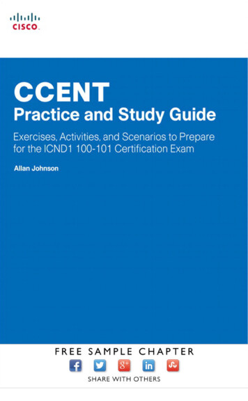
Figure 1.9: Establishing aconnection-oriented sessionThis figure depicts a typical reliable session taking place betweensending and receiving systems. In it, you can see that both hosts’application programs begin by notifying their individual operatingsystems that a connection is about to be initiated.
Figure 1.10: Transmittingsegments with flow control
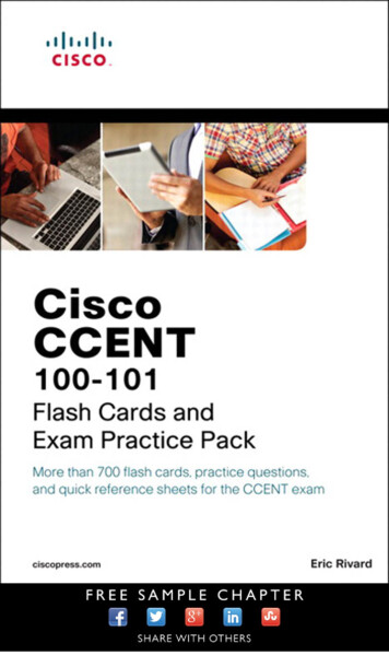
Figure 1.11: WindowingIf you’ve configured a window size of 1, the sending machinewill wait for an acknowledgment for each data segment ittransmits before transmitting another one but will allow three tobe transmitted before receiving an acknowledgment if the windowsize is set to 3.
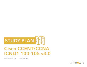
Figure 1.12: Transport layerreliable deliveryIn the figure, the sending machine transmits segments 1, 2, and 3. Thereceiving node acknowledges that it has received them by requestingsegment 4 (what it is expecting next).
Figure 1.13: Routing tableused in a router
Figure 1.14: A router in aninternetworkEach router LAN interface is a broadcast domain. Routers breakup broadcast domains by default and provide WAN services.
Figure 1.15: Data Link layerFigure 1.15 shows the Data Link layer with theEthernet and IEEE specifications.
Figure 1.16: A switch in aninternetworkFigure 1.16 shows a switch in an internetwork and how John issending packets to the Internet and Sally doesn’t hear his framesbecause she is in a different collision domain.
Figure 1.17: A hub in anetworkFigure 1.17 shows a hub in a network, and how when onehost transmits, all other hosts must stop and listen.
Written Labs and ReviewQuestions– Read through the Exam Essentials sectiontogether in class.– Open your books and go through all thewritten labs and the review questions.– Review the answers in class.19
CCENT Study Guide Author: O'Brien, Conn