Transcription
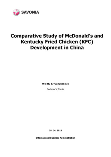
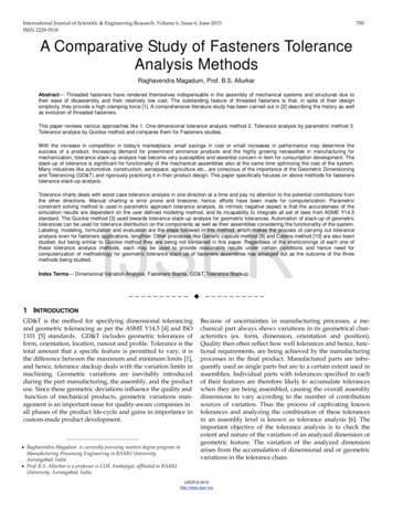
International Journal of Scientific & Engineering Research, Volume 6, Issue 2, February-2015ISSN 2229-5518256Comparative Study of Analysis and Designof R.C. and Steel StructuresProf. Prakarsh Sangave1, Mr. Nikhil Madur2, Mr. Sagar Waghmare3, Mr. Rakesh Shete4, Mr. Vinayak Mankondi5,Mr. Vinayak Gundla6Abstract— The use of steel structure in India as compared to other countries is less, as India is developing country. In cities like Delhi andMumbai, horizontal expansion is restricted therefore vertical growth of building becomes predominant. . Infill walls are probably the mostimportant non-structural element in the context of seismic design. They helps in resisting the lateral forces. Due to their significance inplane stiffness and strength, infill walls modify the anticipated seismic performance of a building. In the present work, three dimensionalmodels of steel & RCC structures are analyzed by using equivalent static method under the provision of IS 1893: (2002) with the help ofETABS software. Where design and cost estimation is carried out using MS-Excel programming for all structures. Comparative study ofbare & infill frame of four models of (G 6) & (G 10) RC & steel structures is carried out which is situated in seismic zone five (v).Masonryinfill is modeled by Equivalent Diagonal Strut method.Index Terms— Bare Frame, Base shear, cost ratio, Displacement, Infill frame, Inter -Storey drift, Strut.—————————— ——————————1 INTRODUCTIONSteel industry is growing rapidly in almost all parts of theworld. Time is most important parameter from the construction point of view and steel structure is built in a shortshort period. Steel structures are more advantageous thanthat of RC structure, because they have better response duringearthquake. In the present work, comparative study of bareand infill frame of RC & steel structure (G 6 & G 10) is included. The comparative study includes base shear, maximumpoint displacement, axial forces and bending moments in thecolumns, material consumption and cost comparisons of RCC& steel structure.A steel building is a metal structure fabricated with steel forthe internal support and for exterior cladding, as opposed tosteel framed buildings which generally uses other materialsfor floors, walls, and external envelope. Steel buildings areused for a variety of purposes including storage, work spacesand living accommodation.2.1 Modeling with ETABS3-D model is being prepared for the frame analysis ofbuilding in ETABS. Following basic parameters are used forthe analysis and design of structures:IJSER2.1.1 Material PropertiesUnit weight of R.C.C25 kN/m3Unit weight of steel78 kN/m3M25 for R.C.C and SteelstructureFe 415 HYSD barsGrade of reinforcing steelGrade of structural steelFe 250Modulus of Elasticity for25 KN/m2R.C.CModulus of Elasticity for210 KN/m2SteelSelf-weight of strucDead loadtural elementsA typical plan of building is selected for comparative study ofRCC and steel structure having plan dimensions 22.5m X 12mas shown in Fig 1.1.5m belowG.L.3m each0.15m thick all150mm thick20 kN/m3Grade of concrete2 STRUCTURAL DETAILSFoundationDepthStorey heightWallsSlab depthUnit weight of masonryLive load4 kN/m2Floor finish load1 kN/m22.1.2 Earthquake parameters:The beams and column location considered for comparisonsof different analysis parameters is studied by grouping them.Group 1: Interior beams and columns.Group 2:Longer direction pheripheral beams & columns.Group 3: Corner columns.Seismic ZoneV (0.36)Soil typeHard (Type 1)Importance factor1Time periodProgram CalculatedEarthquake load inX & Y directionType of diaphragmIJSER 2015http://www.ijser.orgRigid
International Journal of Scientific & Engineering Research Volume 6, Issue 1, January-2015257ISSN 2229-5518Fig 1: Plan view of buildingFig 2: Interior beams and columns (Group1)IJSERFig 3: Longer direction peripheralFig 4: Corner columns (Group3)Beams & Columns (Group 2)Fig 5: 3D View of BuildingR.C. and Steel model has been made. Different column and beam sizes were provided. The analysis and design is carried out for all structures, the result obtained are tabulated and graphically summarized below.IJSER 2015http://www.ijser.org
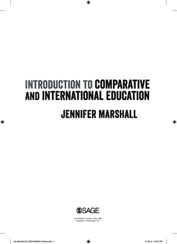
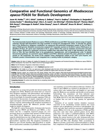
258International Journal of Scientific & Engineering Research Volume 6, Issue 1, January-2015ISSN 2229-55183. COMPARISION OF BASE SHEAR AND DISPLACEMENT OF DIFFERENT MODEL:3.1 Base Shear Comparisons:Table 1 Base Shear Comparison of (G 6) ModelsRC Frame withSteel Bare Framemasonry Infill431.78 kN735.29 kNIn X-DirectionRC BareFrame600.51kNIn Y-Direction567.85 kNBase Shear260.83 kNSteel Frame withmasonry Infill660.96 kN574.04 kN437.19 kNIJSERFig.6: Comparison of Base Shear of (G 6) ModelsBase ShearIn X-DirectionIn Y-DirectionTable 2 Base Shear Comparison of (G 10) ModelsRC Frame withSteel Bare Framemasonry Infill479.98 kN858.67 kNRC BareFrame719.42 kN656.67 kN323.37 kN744.57 kNFig. 7: Comparison of Base Shear of (G 10) ModelsIJSER 2015http://www.ijser.orgSteel Frame withmasonry Infill687.07 kN472.75 kN
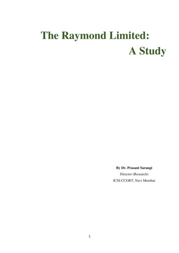
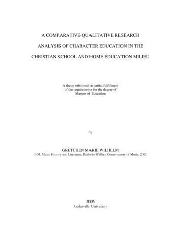
259International Journal of Scientific & Engineering Research Volume 6, Issue 1, January-2015ISSN 2229-55183.2 Max. Storey Displacement Comparisons:Table 3: Maximum Storey Displacement Comparison of (G 6) ModelsDisplacementRC BareFrameBare Frame Steel StructureRC frame with masonryInfillSteel frame withmasonry InfillIn X- Direction36.6 mm49.3 mm31.2 mm33.9 mmIn Y-Direction49.68 mm73.7 mm35.65 mm48.3 mmIJSER. Fig. 8: Comparison of Maximum Storey Displacement of (G 6) ModelsTable 4: Maximum Storey Displacement Comparison of (G 10) ModelsDisplacementIn X- DirectionIn Y-DirectionRC BareFrameSteel Bare FrameRC Frame withmasonry InfillSteel Frame withmasonry Infill30.2 mm34.1 mm19.62 mm22.1 mm36.28 mm56.4 mm23.22 mm32.5 mmFig. 9: Comparison of Maximum Storey Displacement of (G 10) ModelsIJSER 2015http://www.ijser.org
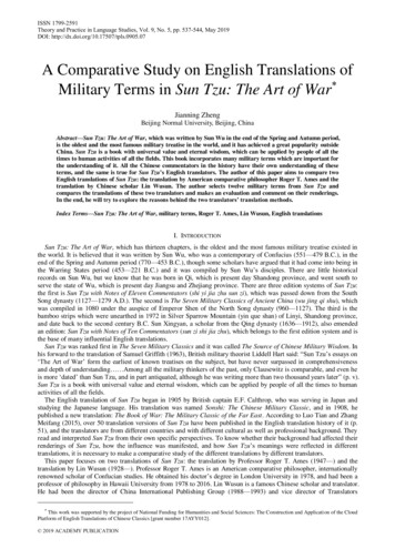
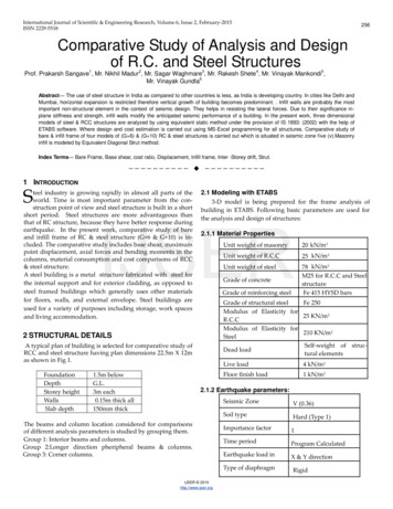
260International Journal of Scientific & Engineering Research Volume 6, Issue 1, January-2015ISSN 2229-55184Axial Forces, Bending Moment, Support Reaction, Storey Drift Comparisons:.Fig. 10 Bending Moment in Columns of (G 6) ModelsIJSERFig.11: Bending Moment In Columns of (G 10) Models.Fig. 12: Axial Forces In Columns of (G 6) ModelsIJSER 2015http://www.ijser.org
International Journal of Scientific & Engineering Research Volume 6, Issue 1, January-2015ISSN 2229-5518Fig. 13: Axial Forces In Columns of (G 10) ModelsIJSERFig. 14: Bending Moment In Beams of (G 6) ModelsFig. 15: Bending Moment In Beams of (G 10) ModelsIJSER 2015http://www.ijser.org261
262International Journal of Scientific & Engineering Research Volume 6, Issue 1, January-2015ISSN 2229-5518.Fig.16:Shear Forces In Beams of (G 6) ModelsIJSERFig. 17: Shear Forces In Beams of (G 10) ModelsFig. 18: Support Reactions of (G 6) ModelsIJSER 2015http://www.ijser.org
International Journal of Scientific & Engineering Research Volume 6, Issue 1, January-2015ISSN 2229-5518IJSERFig. 19: Support Reactions of (G 10) ModelsFig. 20: Inter-Storey Drift of (G 6) ModelsIJSER 2015http://www.ijser.org263
264International Journal of Scientific & Engineering Research Volume 6, Issue 1, January-2015ISSN 2229-5518IJSERFig. 21: Inter-Storey Drift of (G 10) Models5. COST COMPARISONS:Table 3 Cost Comparison of Bare Frame (G 6) ModelsRC Bare Frame(1)Cost ratio(2/1)Steel BareFrame (2)MaterialQuantityUnit RateCostQuantityUnit RateCostConcrete t(tonne)45.594500020515507.8645000353700Structural Steel(tonne)--------------98.84450004448700Total Cost40.73 lac.IJSER 2015http://www.ijser.org59.36 lac.1.45
265International Journal of Scientific & Engineering Research Volume 6, Issue 1, January-2015ISSN 2229-5518Table 4 Cost Comparison of Infill Frame (G 6) ModelsRC Frame withmasonry Infill(1)Cost ratio(2/1)Steel Framewith masonryInfill (2)MaterialQuantityUnit RateCostQuantityUnit RateCostConcrete t(tonne)36.964500016632007.8645000353700Structural Steel(tonne)--------------94.72450004262400Total Cost----------35.81 lac.----------57.50 lac.1.6Table 5 Cost Comparison of Bare Frame (G 10) ModelsRC Bare Frame(1)Cost ratio(2/1)Steel Bare Frame(2)IJSERMaterialQuantityUnit RateCostQuantityUnit RateCostConcrete 50Reinforcement(tonne)Structural Steel(tonne)Total Cost64.53 lac.98.44 lac.1.52Table 6 Cost Comparison of Infill Frame (G 10) ModelsRC Frame withmasonry Infill(1)Cost ratio(2/1)Steel Framewith masonryInfill (2)MaterialQuantityUnit RateCostQuantityUnit RateCostConcrete l Steel(tonne)--------------170.29450007663050Total Cost62.57 lacIJSER 2015http://www.ijser.org1 cr.1.6
International Journal of Scientific & Engineering Research Volume 6, Issue 1, January-2015266ISSN 2229-55186. RESULTS AND DISCUSSION1.2.7. CONCLUSIONS1.In steel bare frame, base shear is decreased by 28% ascompared to RCC along X-direction and 54% along Y-tures because of less seismic weight which gives bet-direction for (G 6) frame.ter response during earthquake.2.In steel frame with masonry infill, base shear is de-3.and 23% along Y-direction for (G 6) frame.4.tures is more as compared to steel structures except inIn steel frame with masonry infill, base shear is de-RC masonry infill structures at corner column.5.6.In steel bare frame maximum storey displacement isdirection and 55% along Y-direction for (G 6) frame.7.Cost ratio of steel and RC bare frame (G 6) is 1.45.In steel frame with masonry infill, maximum storey8.Cost ratio of steel and RC bare frame (G 10) is 1.52.displacement is increased by 12% as compared to RC9.Cost ratio of both (G 6) and (G 10) structures of steelIJSERand RC frame with masonry infill is 1.6.along X-direction and 40% along Y-direction for (G 6)frame.In steel bare frame, maximum storey displacement isincreased by 35% as compared to RC along Xdirection and 48% along Y-direction for (G 10) frame.8.REFERENCES[1]In steel frame with masonry infill, maximum storeydisplacement is increased by 8% as compared to RCalong X-direction and 35% along Y-direction for(G 10) frame.9.Shear forces in beams of RC structures are more ascompared to Steel structures.increased by 13% as compared to RC along X-7.Axial forces and support reactions in columns of RCstructures are more as compared to Steel structures.and 36% along Y-direction for (G 10) frame.6.Bending moment in beams and columns of RC struc-direction for (G 10) frame.creased by 20% as compared to RC along X-direction5.Due to presence of infill in structure maximum pointdisplacement and storey drift reduces slightly.In steel bare frame, base shear is decreased by 33% ascompared to RC along X-direction and 50% along Y-4.Maximum point displacement and storey drift of Steelbare frame is more than RC bare frames.creased by 10% as compared to RC along X-direction3.Base shear in steel structure is less than the RC struc-[2]Bending moment in beams and columns of steel[3]frames is less as compared to RC frames.10. An axial force in steel frames is less than RC frames.11. Shear force in beams of RC frames is more than steel[4]frames.12. Support reactions in RC structures are increased by23% as compared to steel structures due to less self-[5]weight.13. Storey drifts of steel structures are comparativelymore than RC structures within permissible limit.[6]Anamika Tedia, Dr. Savita Maru, “Cost, Analysis and Design of SteelConcrete Composite Structure RCC Structure”, IOSR Journal of Mechanical and Civil Engineering (IOSR-JMCE) e-ISSN: 2278-1684,p-ISSN:2320-334X, Volume 11, Issue 1 Ver. II (Jan. 2014), PP 54-59.[7]Mahesh Suresh Kumawat and L G Kalurkar, “Cost Analysis of SteelConcrete Composite Structure”, ISSN 2319 – 6009, Int. J. Struct. &CivilEngg.Vol. 3, No. 2, May 2014,Kiran Kumar, G. Papa Rao, “Comparison of Percentage Steel And Concrete Quantities Of A R.C Building In Different Seismic Zones”, Department of Civil Engineering, GVP College of Engineering (A), Visakhapatnam, India.14. Cost of steel bare frame is increased by 31% as compared to RC frame for (G 6) frame.15. Cost of steel frame with masonry infill is increased by37% as compared to RC frame for (G 6) frame.16. Cost of steel bare frame is increased by 34% as compared to RC frame for (G 10) frame.17. Cost of steel frame with masonry infill is increased by37% as compared to RC frame for (G 10) frame.Handbook on Code of Practice for Design Loads (Other than Earthquake ) for Buildings and Structures ( IS : 875-1987), Bureau of IndianStandards, New Delhi, 1989. W.-K. Chen, Linear Networks and Systems.Belmont, Calif.: Wadsworth, pp. 123-135, 1993. (Book style)Handbook on Criteria for Earthquake Resistant Design of Structures (IS: 1893 (Part 1) – 2002), Bureau of Indian Standards, New Delhi,1989.K. Elissa, “An Overview of Decision Theory," unpublished. (Unplublished manuscript)IS: 13920-1993- ductile detailing of reinforced of concrete structure subjected to seismic forces code of practice. C. J. Kaufman, Rocky Mountain Research Laboratories, Boulder, Colo., personal communication, 1992.(Personal communication)IS: 456(2000), - Indian Standard Code of Practice for Plan and Reinforcement concrete (Fourth Revisions), Bureau of Indian Standards (BIS),New Delhi.D. R. Panchal and P. M. Marathe, “Comparative Study of R.C.C, Steeland Composite (G 30 Storey) Building ”, Institute of Technology, Nirma University, Ahmedabad – 382 481, December, 2011.[8]IJSER 2015http://www.ijser.org
International Journal of Scientific & Engineering Research Volume 6, Issue 1, January-2015ISSN 2229-5518[9]Institute for steel development & growth, "B G 40 Storied ResidentialBuilding with Steel-Concrete Composite Option”, India Dec 2007.[10] M. Nageh, “How To Model and Design High Rise Building Using ETABsProgram”, Cairo 2007.[11] M. Willford, A. Whittaker and R. Klemencic, “Recommendations forSeismic Design of High-Rise Buildings” Council of Tall building andurban habitat Feb 2008.[12] J. Zils and J. Viis, “An Introduction to High Rise Design”, StructureMagazine Nov 2003. Prof. Sangave P. A. is Associate Professor in Nagesh Karajagi Orchid college ofEngineering, Solapur. India, E-mail: psangave@gmail.com. Mr. Nikhil Madur is Under Graduate Student of Civil EngineeringDepartment, Nagesh Karajagi Orchid College of Engg. and Tech., Solapur,Maharashtra, India, Email: nikhilmadurengg@gmail.com PH:8421532959. Mr. Sagar Waghmare Under Graduate Student of Civil Engineering Department, Nagesh Karajagi Orchid College of Engg. and Tech., Solapur, Maharashtra,India, Email: sagarpw1991@gmail.com PH:8793507044. Mr. Rakesh Shete is Under Graduate Student of Civil Engineering Department,Nagesh Karajagi Orchid College of Engg. and Tech., Solapur, Maharashtra, India,Email: rakeshshete7@gmail.com PH:8485819064.IJSER Mr. Vinayak Mankondi Under Graduate Student of Civil Engineering Department, Nagesh Karajagi Orchid College of Engg. and Tech., Solapur, Maharashtra,India, Email: vpm2715@gmail.com PH:9730735332. Mr. Vinayak Gundla is Under Graduate Student of Civil Engineering Department, Nagesh Karajagi Orchid College of Engg. and Tech., Solapur, Maharashtra,India, Email: gundlavinayak@gmail.com PH:9890571845.IJSER 2015http://www.ijser.org267
Where design and cost estimation is carried out using MS-Excel programming for all structures. Comparative study of bare & infill frame of four models of (G 6) & (G 10) RC & steel structures is carri