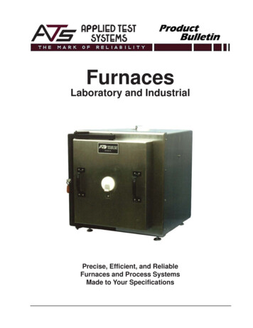
Transcription
Oil FurnacesPMP-098 MULTI-POSITIONKEEP THESE INSTRUCTIONSWITH FURNACE FOR FUTUREREFERENCE.CFurnace Manual1.2.3.4.5.6.7.USPageContentsRead this first!. 2Installation. 3Operation . 12Maintenance . 14Checkout procedure . 15Dimensions and ratings . 17Components and replacement parts. 23Owner’s information. 27Hazard definitionsHazards that will cause severe personal injury, deathor substantial property damage.Hazards that will or can cause minor personal injuryor property damage.Hazards that can cause severe personal injury, deathor substantial property damage.Special instructions on installation, operation ormaintenance that are important but not related topersonal injury or property damage.INSTALLER – Read all instructions beforeinstalling. Read page 2 first. Follow allinstructions in proper order to prevent personalinjury or death. Consider ducting, fuel supply, venting andinstallation when determining furnace location. Any claims for damage or shortage in shipmentmust be filed immediately against thetransportation company by the consignee.Do not store or use gasoline or other flammable liquidsor vapors near this furnace or any other appliance.Ventilate house while operating furnace for the firsttime. Odors may be emitted for a brief period.Do not alter this furnace in any way. The manufacturerwill not be liable for any damage resulting fromchanges made in the field to the furnace or itscomponents or from improper installation. Failure tocomply could result in severe personal injury, death orsubstantial property damage.USER – Please read the following. Failure tocomply could result in severe personal injury, deathor substantial property damage. This manual is for the sole use by yourqualified heating installer / service technician. Please see the Owner’s information only, on theback page of this manual. Have the furnace serviced by a qualified servicetechnician, at least once a year.This manual must only be used by a qualifiedheating installer / service technician. Furnace andburner must be installed and serviced only by aqualified heating installer / service technician. Failureto comply could result in severe personal injury, deathor substantial property damage.When calling or writing about the furnace – Pleaseindicate furnace model number and serial numberfrom rating label. You may list the serial number andmodel number in the space provided on the“Installation and service certificate” found on page 16If your furnace is shut down during the cold weather season, water pipes may freeze, burst and cause serious water damage. Turnoff the water supply and bleed the pipesIf the heater is left unattended during the cold weather season, take the following precautions:Close the main water valve in the house and purge the pipes if possible. Open all the faucets in the house;Ask someone to frequently check the house during the cold weather season to make sure that there is sufficient heat to prevent thepipes from freezing. Tell this person to call an emergency number if requiredPrinted on 100 % recycled paper11/13
READ THIS FIRST!Failure to adhere to the guidelines below can result in severe personal injury, death or substantial property damage.Service and maintenance –1.To avoid electric shock, disconnect electrical supply beforeperforming maintenance.To avoid severe burns, allow furnace to cool before performingmaintenance.Perform service and maintenance as described in this manualand the burner manual.Do not attempt to make adjustments to the blower or motor whilethe furnace is in operation. Disconnect power to the furnace andbe sure all parts have stopped moving before attemptingadjustments or maintenance.The burner must be set up and adjusted using combustion testinstruments. Visual examination of the flame alone cannotdetermine combustion performance.2.3.4.5.Operation 6.7.8.9.10.11.12.13.Do not use the furnace as a construction heater.Do not operate any furnace if the heat exchanger is damaged,corroded or pitted. Toxic flue products could enter the air stream.Do not jumper, attempt to by-pass or override any limit control.Do not block flow of combustion or ventilation air to furnace. Donot block or obstruct the air openings in the furnace casing.Do not store or use combustible materials, gasoline, or otherflammable liquids or vapors in the furnace area.Do not operate the furnace if the furnace area will be exposed toair contaminants as described on page 7Should overheating occur, do not turn off or disconnect electricalsupply to furnace. Instead, shut off the oil supply at a locationexternal to the appliance, if possible.Do not use this furnace if any part of it has been under water.Call a qualified service technician immediately, to inspect thefurnace and to replace any part of the furnace, control system orburner that was submerged in water.14. Do not operate furnace if temperature rise through heatexchanger exceeds 85 F.15. Inspect, clean and replace (if necessary) return air filter regularly.16. Do not obstruct return air grills or supply air outlets.17. Supply only with #2 fuel oil to the burner. Never attempt to usegasoline, a mixture of gasoline and oil, waste fuel, reused or anyother substance in the burner of furnace.Installation 18. Do not block flow of combustion or ventilation air to furnace. Donot block or obstruct the air openings in the furnace casing.19. Connect furnace only to a functional vent system in goodcondition. Place the furnace to allow proper venting, with theshortest possible venting and minimum number or elbows.20. Always connect and seal a return air duct to the furnace unlessthe furnace is located in a large space, such as an unpartitionedbasement. Route the return air duct to an adjacent room if noreturn air manifold is used.21. Install furnace maintaining minimum clearances for service andseparation from combustible surfaces described in this manual.22. Install, start-up, service and maintain burner per instructions inthis manual and the burner manual.23. Verify burner is properly inserted through the combustionchamber opening.24. Furnace must be installed so that burner and control systemcomponents are protected from dripping, spraying water or rainduring operation or service.25. If installing an air conditioning evaporator coil, install the coildownstream of, or in parallel with, the furnace to preventcondensation on the furnace heat exchanger. If the coil is inparallel, provide means to prevent flow of chilled air into thefurnace, including an interlock to prevent simultaneous operationof heating and air conditioning.Apply the following suggestions to prevent unsatisfactory operation of the furnace.Installation –1.Be sure to level the furnace, using a spirit level on the front andone side. If the furnace is not level, oil can drip into thecombustion chamber after burner cycling and contaminate theheat exchanger and the burner head.2. Make sure all legs are in contact with the floor to distribute theload and prevent the possibility of undue noise or vibration.3. Avoid locating return grills in rooms that may contain undesirableodors.4. Never locate a return air grill closer than approximately 20 feetfrom the furnace.5. Locate the furnace near the center of the supply and return ductsystems.6. Always check the size of the ducts on a replacement installation,particularly if adding air conditioning.It is recommended that carbon monoxide detectors be installed wherever oil or gas fired heaters are used. Carbon monoxide cancause bodily harm or death. For this reason, agency approved carbon monoxide detectors should be installed in your residenceand properly maintained to warn of dangerously high carbon monoxide levelsThere are several sources of possible smoke and flames in a residence. Smoke and flames can cause bodily harm or death. For thisreason, agency approved smoke detectors should be installed in your residence and properly maintained, to warn early on, of apotentially dangerous fire. Also, the house should be equipped with approved and properly maintained fire extinguishers.Your unit is equipped with safety devices that can prevent it from functioning when anomalies are detected such as the optionalBlocked Vent Shut-off Device.211/13
PMP-098 Oil Furnaces – Furnace Manual1. INSTALLATIONThe unit is shipped with a burner and its controls. It requires an 115VAC power supply to the control panel and thermostat hook-up asshown on the wiring diagram, one or more oil line connections,suitable ductwork and connection to a properly sized vent.All local and national code requirements governing the installation ofoil burning equipment, wiring and the flue connection MUST befollowed. Some of the codes that may apply are:CSA B139:Installation code for oil burningequipment.ANSI/NFPA 31:Installation of oil burning equipment.ANSI/NFPA 90B:Warm air heating and air conditioningsystems.ANSI/NFPA 211:Chimneys, Fireplaces, Vents and solidfuel burning appliances.ANSI/NFPA 70:National Electrical Code.CSA C22.1:Canadian Electrical Code.The unit must be installed in an area where the ambient and returnair temperatures are above 15 C (60 F). In addition, the furnaceshould be installed as closely as possible to the vent, so that theconnections are direct and kept to a minimum. The heater shouldalso be located close to the centre of the air distribution system.1.1.1.Installation in an enclosureThe unit can be installed in an enclosure such as a closet. However,2 ventilation openings are required for combustion air. The openingsshould be located in front of the furnace approximately 15 cm (6")above the floor and 15 cm (6") below the ceiling. Figure 1 indicatesthe minimum dimensions required and the location of the openings.Figure 1: Location and dimensions of ventilation airopenings in a closet dooror CSA C22.10:Only the latest issues of these codes may be used.1.1.POSITIONING THE FURNACEFire and explosion hazard.The furnace must be installed in a level position,never where it will slope toward the front.Do not store or use gasoline or any otherflammable substances near the furnace.Non-observance of these instructions willpotentially result in death, bodily injury and/orproperty damage.This furnace is not watertight and is not designedfor outdoor installation. It must be installed insuch a manner as to protect its electricalcomponents from water. Outdoor installation willlead to a hazardous electrical condition and topremature failure of the equipment.The minimum clearances from combustible material for each ofthe positions are specified in Table 1.If the furnace is installed in a basement or on a dirt floor, in a crawlspace for example, it is recommended to install the unit on a cementbase 2.5 cm to 5.0 cm (1" to 2") thick.Table 1: Minimum clearances from combustible materialsLOCATIONSIDESFURNACEPLENUM AND WARM-AIR DUCT WITHIN 6 ft. OF FURNACEBOTTOM FURNACEBACKTOP12FURNACE (OPPOSITE SIDE OF THE BURNER) 1PLENUM OR HORIZONTAL WARM-AIR DUCT WITHIN 6 ft. OF FURNACEFURNACE2FLUE PIPE AROUND FLUE PIPE1FRONT FURNACE (BURNER SIDE)11/1311These are horizontal dimensions2These are vertical dimensions2UPFLOWHORIZONTALDOWNFLOW2.54 cm (1")N/A2.54 cm (1")5.08 cm (2")Ø2.54 cm (1")2.54 cm (1")35.08 cm (2")5.08 cm (2")47.62 cm (3")2.54 cm (1")7.62 cm (3")5.08 cm (2")5.08 cm (2")5.08 cm (2")N/A5.08 cm (2")N/A22.86 cm (9")22.86 cm (9")22.86 cm (9")45.72 cm (18")45.72 cm (18")45.72 cm (18")3
PMP-098 Oil Furnaces – Furnace Manual1.2.1.2.1.CONFIGURATIONS1.2.3.Upflow InstallationThe return air opening may be located on either side of the furnace.Care should be taken not to damage the wires inside, while cuttingthe opening. Install the filter rack supplied with the unit according tothe instructions provided with it. It is also recommended to install theblower door before handling or moving the unit. Refer to figure 2 foradditional details.Figure 2:Upflow installationHorizontal InstallationWhen the furnace is installed in the horizontal position, eithersuspended or on a combustible floor with a choice of right or leftdischarge, the clearances from combustible material must beadhered to. If the unit is installed on a combustible floor, thehorizontal floor base HFB-101 can be used to ensure theseclearances. Refer to the instructions supplied with the base.The burner must always be installed in the same manner, regardlessof the discharge position of the furnace. Refer to Figure 4 foradditional details.Figure 4: Horizontal installationBurner positionFilter 20" x 20"Horizontal floor baserequired forcombustible floorCombustible or noncombustible floor1.3.1.2.2.The burner must always be installed in the same manner, regardlessof the discharge position of the furnace. Refer to Figure 3 foradditional details.The protection plate (B03789) must be installed on the plastic coverof the Beckett NX burner to protect it from vent.Figure 3: Downflow installationELECTRICAL SYSTEMThe exterior of the unit must have anuninterrupted ground to minimize the risk ofbodily harm, if ever an electrical problemdevelops. A green ground screw is supplied withthe control box for that purpose.Downflow InstallationWhen the furnace is installed in the downflow position on acombustible floor, the clearances from combustibles must beadhered to. The downflow base DFB-102 can be used to ensurethese clearances. Refer to Figure 3 and the installation instructionsprovided with the base.Filter rack 20" x 20"The appliance must be installed in accordance with the currentANSI/NFPA 70 National Electrical Code, CSA C22.1 CanadianElectrical Code Part 1 and/or local codes.The control system depends on the correct polarity of the powersupply. Connect “HOT” wire (H) and “NEUTRAL” wire (N) as shownin figures 10 and 11.A separate line voltage supply should be used, with fuseddisconnect switch or circuit breaker, between the main power paneland the unit.Only copper wire may be used for the 115V circuit on this unit. Ifwires need to be changed, the replacements must have the sametemperature resistance as the originals.Filter rack 20" xFloor Return Base1.4.INSTALLATION OF THE THERMOSTATA thermostat must be installed to control the temperature of the areato be heated. Follow the instructions supplied with the thermostat.Also refer to the wiring diagrams provided with the heating/airconditioning unit. The connections must be made as indicated on thefollowing diagrams and the wiring diagrams, figures 10 and 11.Burner positionDownflow base isrequired forcombustible floor411/13
PMP-098 Oil Furnaces – Furnace ManualFigure 5: Thermostat wiring, heating and airconditioning with 4-speed motorFigure 6: Thermostat wiring heating and air conditioningwith ECM variable speed motor1.5.INSTALLATION OF THE BURNERRefer to the burner manufacturer’s instructions. Also, the burnermust be installed always in the same way independently of thefurnace orientation.1.Position the mounting gasket between the mounting flange andthe burner mounting plate. Align the holes in the burnermounting plate with the studs on the mounting flange and boltsecurely in place.2.Remove the burner drawer assembly or the air tube assembly;3.Install the nozzle, refer to Burner data Table 11;4.Check the electrode settings;5.Make the electrical connections;6.Complete oil line connections.1.5.1.NozzlesThe burner comes equipped with an appropriate nozzle. However, ifanother size or a replacement nozzle is required, use themanufacturer’s recommended spray angle and type as shown inTable 11 and pump pressure as specified.Always select nozzle sizes by working back from the desired flowrate at operating pressure and not the nozzle marking.1.5.2.Air and Turbulator SettingsBefore starting the burner for the first time, adjust the air andturbulator settings to those listed in this manual, Table 11. Once theburner becomes operational, final adjustments will be required.Refer to section 2 of this manual.1.5.3.Post purge delay adjustmentThe post purge delay on the oil-fired burners is factory set to zerosecond. This delay is applicable for all installations with chimneyventing. For heating units installed with side wall venting and aburner equipped with this feature, the post purge delay must be setto 15 seconds (For configuration use the Beckett Contractor’s Tool"52082U"). No delay is required for Riello burners. Refer to theburner control instruction manual and markings for properadjustment of the post purge delay.Figure 7: Thermostat wiring, heating and air cond. heatpump with ECM v. speed motor1.6.VENTINGPoisonous carbon monoxide gas, fire andexplosion hazard.Read and follow all instructions in this section.Failure to properly vent this furnace can result indeath, bodily injury and/or property damage.To ensure the safe and proper functioning of anoil furnace, it must always be connected to a fluewith sufficient draft or to an approved side-wallventing system. In addition, it is stronglyrecommended to perform a complete inspectionof all the existing venting systems.Poisonous carbon monoxide gas hazard.Never install a hand operated damper in the ventpipe. However, any Underwriters Laboratorieslisted, electrically operated automatic type ventdamper may be installed if desired. Be sure tofollow the instructions provided with ventdamper. Also, read and follow all instructions inthis section of the manual.Note:11/13On units with 2 stage cooling or heat pump, terminal Y1must be used. When Y1 on the electronic controlreceives a 24 VAC signal, the air flow is reduced by20%. Do not use terminal Y1 with a single stage coolingor heat pump.Failure to properly vent this furnace or otherappliances can result in death, bodily injuryand/or property damage.5
PMP-098 Oil Furnaces – Furnace Manual1.6.1.Masonry chimneyThis furnace can be vented into an existing masonry chimney.However, the unit must not be vented into a chimney into which asolid fuel burning furnace is already being vented.Figure 8: BVSO mounting installation: Upflow withvertical exhaust (OPTIONAL)Before venting this furnace into a chimney, its condition must bechecked and repairs made, if necessary. Also, the chimney liningand dimensions must conform to local and national codes.1.6.2.Factory Built ChimneysOil fired furnaces are approved for use with “L” type vents. The unitmay also be used with an approved chimney of proper dimensionsand temperature ratings as specified in the installation code. Referto chimney manufacturer’s instructions for proper installation.1.6.3.Draft RegulatorIt is recommended that a draft regulator be installed in cases wherethe draft is either high or variable due to external conditions. Followthe instructions provided with the regulator.1.6.4.Side-wall VentingThe heating unit is approved for side-wall venting. This system iscomprised of a model VTK-54 side-wall venter and a 4” insulatedvent pipe, model IFV-410, IFV-420. Refer to the installationinstructions provided with the venting system.1.7.BLOCKED VENT SHUT-OFF DEVICE(BVSO) FOR CHIMNEY VENTING OPTIONALFigure 9: BVSO mounting installation: Upflow withhorizontal exhaust (OPTIONAL)It is imperative that this device be installed by aqualified service technician.A positive pressure venting system (SealedCombustion System or Direct Vent) must NOT usethe BVSO. Follow the instructions supplied withthe venting system.This device is designed to detect the insufficient evacuation ofcombustion gases in the event of a vent blockage. In such a casethe thermal switch will shut down the oil burner. The device will thenneed to be re-armed MANUALLY.Refer to the detailed instructions and wiring diagrams supplied withthe BVSO for the installation and wiring procedures. The length ofwires supplied with the unit is such that the safety device must beinstalled between the flue outlet of the appliance and the draftregulator, as indicated in the instructions.Figure 10: BVSO Wiring (OPTIONAL)It is also essential that the BVSO be maintained annually. For moredetails refer to the instructions supplied with the device itself, as wellas Section 2 of this Manual.1.7.1.BVSO Performance Test(If installed)The purpose of the following test is to check that the electrical outleton the furnace, designated to the BVSO, is functional.1.2.3.Start up the burner;Disconnect one wire of the BVSO;The burner must shut-off immediately, while the blowercontinues to run to the end of the cool-down cycle.If the test is not in line with the above, call a QUALIFIED SERVICETECHNICIAN.611/13
PMP-098 Oil Furnaces – Furnace Manual1.8.COMBUSTION AIR SUPPLY ANDVENTILATION1.9.OIL TANKFire and explosion hazard.Use only approved heating type oil in this furnace.DO NOT USE waste oil, used motor oil, gasoline orkerosene.Use of these will result in death, bodily injuryand/or property damage.When a 0.75 USGPH or smaller nozzle is used, a 10micron or finer filter, must be installed on the oilsupply line to the furnace inside the building wherethe unit is located.This is a requirement in order for the heatexchanger warranty to remain in force.Poisonous carbon monoxide gas hazard.Comply with NFPA 31 (U.S.) and CSA B139 (Canada)standards for the installation of Oil BurningEquipment and applicable provisions of local buildingcodes to provide combustion and ventilation air.Failure to provide adequate combustion andventilation air can result in death, bodily injury and/orproperty damage.Oil furnaces must have an adequate supply of combustion air. It iscommon practice to assume that older homes have sufficientinfiltration to accommodate the combustion air requirement for thefurnace. However, home improvements such as new windows,doors, and weather stripping have drastically reduced the volume ofair infiltration into the home.Check your local codes for the installation of the oil tank andaccessories.Refer to oil furnace installation codes relative to combustion andventilation air requirements. Consult Section 1.3 in this manual,specifically for units installed in an enclosed space.Ensure that the tank is full of clean oil. Use No.1 or No.2 Heating Oil(ASTM D396 U.S.) or in Canada, use No.1 or No.2 Furnace Oil.Home air exhausters are common. Bathroom and kitchen fans,power vented clothes dryers and water heaters all tend to create anegative pressure condition in the home. Should this occur thechimney becomes less and less effective and can easily downdraft.In certain cases, mechanically supplied air, by way of a blower,interlocked with the unit, is necessary. It is the installer’sresponsibility to check that.1.8.1.Contaminated Combustion AirAt the beginning of each heating season or once a year, check thecomplete oil distribution system for leaks.A manual shut-off valve and an oil filter shall be installed insequence from tank to burner. Be sure that the oil line is cleanbefore connecting to the burner. The oil line should be protected toeliminate any possible damage. Installations where the oil tank isbelow the burner level must employ a two-pipe fuel supply systemwith an appropriate fuel pump. A rise of 2.4 m (8') and more requiresa two stage pump and a rise greater than 4.9 m (16') an auxiliarypump. Follow the pump instructions to determine the size of pipeneeded in relation to the rise or to the horizontal distance.Installations in certain areas or types of structures will increase theexposure to chemicals or halogens that may harm the furnace.These conditions will require that only outside air be used forcombustion.The following areas or types of structures may contain or beexposed to certain substances, potentially requiring outside air forcombustion:1.10.a.b.c.The temperature rise through the furnace must not exceed 85 F, butshould be at least 55 F for comfort. When calculating airflow,assume a temperature rise of 70 F.Commercial buildings;Buildings with indoor pools;Furnaces installed near chemical storage areas.Exposure to the following substances:a.b.c.d.e.f.g.h.i.j.k.l.m.Permanent wave chemicals for hair;Chlorinated waxes and cleaners;Chlorine based swimming pool chemicals;Water softening chemicals;De-icing salts or chemicals;Carbon tetrachloride;Halogen type refrigerants;Cleaning solvents (such as perchloroethylene);Printing inks, paint removers, varnishes, etc. ;Hydrochloric acid;Solvent based glue;Antistatic fabric softeners for clothes dryers;Acid based masonry cleaning materials.1.8.2.Burner with Outdoor CombustionAir KitSome burners are designed to function with combustion air takendirectly from the outside. Follow the instructions provided with theburner, the fresh-air supply kit or the side-wall venting kit.11/13CONNECT SUPPLY AND RETURNDUCTS1.10.1.1.10.1.1.Duct sizingDetermine airflow CFMoThe noticeable temperature change for cooling would beapproximately 27 - 30 F. Actual temperature change will beapproximately 18 - 21 F due to humidity of the air.To calculate noticeable heat temperature change (ΔT), you can usethe formula:ΔT BTU/h / (1.1 x CFM)Eq. 3 - 1To calculate air flow when you know temperature change (ΔT), youcan use:CFM BTU/h / (1.1 x ΔT)Eq. 3 - 2You can estimate air flow using the following rules of thumb:Heating:Cooling:14 CFM per 1,000 BTU/h output400 CFM per ton air conditioningEq. 3 - 3Eq. 3 - 4Determine the required airflow based on whichever is larger: heatingmode or air conditioning mode.Examples:1. What would the temperature rise be for a 100,000 BTU/h outputfurnace with an airflow rate of 1200 CFM?Use Equation 3 - 1 since you know CFM and BTU/h:ΔT 100,000 / (1.1 x 1200) 76 F The temperature rise would be 76 F. If the air enters the furnace at 70 F, it would leave thefurnace at 70 F 76 F 146 F.7
PMP-098 Oil Furnaces – Furnace Manual2. What would the airflow be to obtain a 70 F rise through a120,000 BTU/h output furnace?Table 2: Suggested maximum flow to runoutsUse equation 3 - 2 since you know ΔT and BTU/h:CFM 120,000 / (1.1 x 70) 1558 CFM The air flow would have to be 1558 CFM to obtain atemperature rise of 70 F.3. Estimate the required airflow for a 75,000 BTU/h output furnaceinstalled with a 2-ton air conditioning evaporator coil.CFMTAKE-OFF SIZE(Inches)SUPPLYRETURN45Sheet metal or ductboard5 Round60Heating mode air flow (use Equation 3 - 3):6 Round10075CFM 75 x 14 1050 CFM7 Round140110Cooling mode air flow (use Equation 3 - 4):CFM 2 x 400 800 CFM The larger number is 1050 CFM (heating), so the ductsystem should be sized for 1050 CFM.The supply duct would need to be 16” round or a rectangularequivalent such as 8” x 25" or 12" x 18", using Table 3.4. Estimate the required airflow for the same furnace installed witha 4-ton air conditioning evaporator coil.Heating mode airflow is still 1050 CFM.Cooling mode air flow (use Equation 3 - 4):CFM 4 x 400 1600 CFM The larger number is 1600 CFM (cooling), so the ductsystem should be sized for 1600 CFM.The supply duct would need to be 18” round or a rectangularequivalent such as 8" x 36" or 12" x 23", using Table 3.Always check the size of existing ducts, particularly ifyou are adding air conditioning. The air pressure lossthrough the cooling evaporator coil reduces availableairflow. If the ducts are too small as well, the systemmay not work satisfactorily on either heating orcooling.1.10.1.2.8 Round2101603 ¼ x 8 Stack70553 ¼ x 10 Stack100753 ¼ x 14 Stack1401102 ¼ x 12 Stack70552 ¼ x 14 Stack9070Flexible duct (keep bends to minimum)6 Round55408 Round1209010 Round20016012 Round32025014 Round48037516 Round66053018 Round88068020 Round1200900Determine duct dimensionsTable 3, page 9 and Table 4, page 10, provide typical round andrectangular duct sizes for rectangular and flat oval galvanized ducts.Do not apply these tables to size ductwork if the total equivalentlength of the duct exceeds approximately 100 feet. For longersystems or for duct board, fiberglass-lined or flexible duct sizing, usethe ACCA Manual D or the ACCA duct sizing slide rule. Thesetables are based on pressure loss of approximately 0.10” watercolumn per 100 feet equivalent length of duct.Use Table 2 beside to size or check sizing of take-offs to supplyregisters or return grills.Verify the size and type of registers, diffusers and grills from themanufacturer’s ratings. Do not exceed the recommended flow rate.The pressure drop allowance for each should not exceedapproximately 0.05” water column.Install a return air filter, sized per specifications in Section 5.Use only a return air filter mounted to the furnace. Do not addadditional filters unless the duct system is carefully sized to allow forthe additional pressure drop.811/13
PMP-098 Oil Furnaces – Furnace Manual1.10CONNECT SUPPLY AND RETURN DUCTS (continued)1.10.1 Duct sizing (continued)Table 3: Typical duct sizing for systems not over 100 feet equivalent length – round or rectangular galvanizedTypical duct sizing(For approximately 0.10 inch w.c. in a typical residential installation of galvanized metal duct)Round Rectangular duct equivalent sizesMinimum width (inches) for duct heights (inches) of :ductCFMdiameter 2111099887120016-54413327242117151312111099881300
PMP-098 Oil Furnaces – Furnace Manual 11/13 3 1. INSTALLATION The unit is shipped with a burner and its controls. It requires an 115 VAC power supply to the control panel and thermostat hook-up as shown on the wiring diagram, one or more oil line connections, s