Transcription
ASME B31.3 App-S ExamplesAnalysis of ASME B31.3 Appendix-S ExampleswithSIMFLEX-II Pipe Stress Software and ApproachPrepared by L. C. Peng2-23-2013Ref: ASME B31.3 “Process Piping”, Appendix-S“Piping System Stress Analysis Examples”1. IntroductionASME B31.3 Appendix-S outlines some approaches and methods of analyzing pipingsystem to comply with code stress requirements. The following three examples arepresented each with unique characteristics of code requirements to be complied.A. Example 1 is just a routine simple piping system. The main idea here is tocalculate sustained stress and displacement stress to meet the code requirements.B. Example 2 emphasizes the potential of inactive resting supports during operatingcondition. These lift-off supports are to be considered inactive for the sustainedstress calculation as the hot condition is the most critical for sustained stressC. Example 3 presents the method of calculating displacement stress range ofsystems with stress reversal during different operating conditions.The examples and expected analysis results are given in the attached duplicate ofAppendix-S. This report presents the methods and results as analyzed by SIMFLEX-IIprogram. The analyses can be handled by SIMFLEX-II very easily and the SIMFLEX-IIresults agree very well with Appendix-S results. The analyses are presented example byexample in the following.1
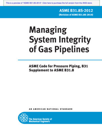
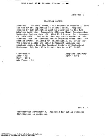
ASME B31.3 App-S Examples2. Example No.1The system is as shown in Fig. S301.1 of the code attached. To describe the system toSIMFLEX-II, the following input data file is needed:***** Input Data *****************************************ASME B31.3 SIMPLE CODE COMPLIANT MODEL - EXAMPLE-1APPENDIX S, S300.1***************** COMMENTS (STARING WITH AN ASTERISK) ********************* SIMFLEX USE SG 8.03 (0.29) FOR CARBON AND LOW ALLOY STEELS** B31.3 EXAMPLE USES (0.283) 7.836 (NEED MANUAL ENTRY)** SIMFLEX DEFAULT WILL INCLUDE PRESSURE ELONGATION** B31.3 EXAMPLE DOES NOT, MANUALLY SET PELONG 2** SIMFLEX ADD 15% FOR MESH AND COVERING FOR INSULATION WEIGHT** FOR IDEN 11, SET TO 11*0.85 9.35 TO GET EQUIVALENT NUMBER AS EXAMPLE******* DISPLACEMENT STRESS RANGE ALLOWBLE** B31.3 EXAMPLE USES 302.3.5 EQ.(1a) SA f(1.25Sc 0.25Sh)** SIMFLEX DEFAULT USES EQ.(1b)SA f[1.25(Sc Sh) - SL)** TO MATCH EXAMPLE USE AN TALLOW 2 OPTION, WHICH HAS LESS ********************************OPTION, CODE 3, COMPL, TTWO, TW, AMB 70, PSIF, UNTOL 12.5, SUPPORTPELONG 2, TALLOW 2SPIPE1, D -16, THK STD, ITHK 5, MATL A106/B, SG 7.836, CSG 1.0TEMP (500, 30), P 500, CA 0.063, IDEN 9.35************10, ANCH, PIPE115, X 2020, X 20, STY30, X 10, BR40, Y 20, BR45, X 15,50, X 15, ANCHENDThe lines starting with an asterisk are comment lines, which are not needed but are usedas comments. These data generate a system as shown on the isometric and resulting acode stress compliance chart shown in the following.2
ASME B31.3 App-S ExamplesIsometricCode Stress Compliance Chart, all stresses are within the allowable shown in green3
ASME B31.3 App-S Examples2A – Operating Load Case Result (This is the TW-1 results)The SIMFLEX-II result printouts are given as follows:123 FEB 13 PENG ENGINEERING, HOUSTON - SIMFLEX-II (RE-9.0 ) (ASME-B31.3) PAGE ------------------------------------ASME B31.3 SIMPLE CODE COMPLIANT MODEL - EXAMPLE-1APPENDIX S, S300.1DATA FILE : B313-S301-1.CASE 4 TH WT RESULTS****************LOAD THM,WGT,BWG,FOR,UFR,CSP,PRESMAX ECH 1.0000*** MEMBER FORCES (ACTING ON PIPE) AND DISPLACEMENT -----------------------------MEMBER DATA----- FORCES (LBS) -------- MOMENTS (FT-LBS) ---DISPLACEMENTS (IN)ROTATION 00.00015-59804740007898.721 -.053.000.000.000.015RUN155980-474000-7898.721 .000.000.000 -.063RUN20598010347000348261.443.000.000.000.000 -.06330A-5980-9017000426281.731 -.142.000.000.000 -.044BEND30A59809017000-426281.731 -.142.000.000.000 -.04430B-5980-8756000517031.760 -.087.000.000.000.311BEND30B59808756000-517031.760 00.000.69240B-5980-5573000-52507 -1.038.701.000.000.000.317BEND40B5980557300052507 -1.038.701.000.000.000.31740C-5980-5312000-48324 -1.010.755.000.000.000 -.060RUN40C5980531200048324 -1.010.755.000.000.000 -.06045-5980-31510006689-.541.342.000.000.000 -.180RUN4559803151000-6689-.541.342.000.000.000 *************************MAXIMUM AT POINTS202050505040B30B40C50505040AThe results match almost exactly the results given in Table S301.5.1 of the code attached.4
ASME B31.3 App-S Examples2B – Sustained Stress (W P)The SIMFLEX-II sustained stresses as printed are given as follows:123 FEB 13 PENG ENGINEERING, HOUSTON - SIMFLEX-II (RE-9.0 ) (ASME-B31.3) PAGE -----------------------------------ASME B31.3 SIMPLE CODE COMPLIANT MODEL - EXAMPLE-1APPENDIX S, S300.1DATA FILE : B313-S301-1.CASE 1 WEIGHT RESULTS****************LOAD WGT,FOR,UFR,PRESMAX ECH 1.0000*** PIPE STRESSES ------------------------MEMBER DATA PIPE CROSS SECTN-- FORCES ------ MOMENTS ---- STRESS-INTN---------- STRESSES ---------TYPEPTODAREAMODULAXIAL SHEARTORSION BENDING OUT-P IN-PHOOP LONGI TRESCA EQUIV(IN) (IN2) (IN3)(LB)(LB)(FT-LB) (FT-LB)(PSI) (PSI) (PSI) --------------------------RUN1016.00 15.3859.2-7342611012699 1.000 1.000126218939 12652257615-73471206290 1.000 1.000126217639 126221276RUN1516.00 15.3859.2-73471206290 1.000 1.000126217639 12622127620-7344037041216 1.000 1.00012621 14723 148478361RUN2016.00 15.3859.2-7346307041216 1.000 1.00012621 14723 15006836130A-734497703920 1.000 1.000126217158 12696795BEND30A16.00 15.3859.2-734497703920 1.624 1.949126217913 12708155030B-38542814010354 1.624 1.94912621 10254 126764094BEND30B16.00 15.3859.2 -38542814010354 1.624 1.94912621 10254 12676409430C-4454734012028 1.624 1.94912621 10876 126264756RUN30C16.00 15.3859.2 -4454734012028 1.000 1.000126218561 12623244040A-17947340268 1.000 1.000126216348 1262254BEND40A16.00 15.3859.2 -17947340268 1.624 1.949126216400 1262210640B-16045640177 1.624 1.949126216376 1262170BEND40B16.00 15.3859.2 -16045640177 1.624 1.949126216376 126217040C-734127201719 1.624 1.949126217042 12625680RUN40C16.00 15.3859.2-734127201719 1.000 1.000126216711 1262534945-73488804217 1.000 1.000126217218 12623855RUN4516.00 15.3859.2-73488804217 1.000 1.000126217218 1262385550-7343382027812 1.000 1.00012621 12004 *********************************MAXIMUM STRESSES12621 14723 150068361AT POINTS50202020The axial forces and bending moments are almost exactly the same as the results given inTable S-301.6 of the code attached. The stresses, shown as “LONGI” stresses, aresomewhat greater than those given in the code table. For instance the stress at support-20is 14,724 psi vs. 14,370 psi of code. The stress at bend-30 is 10876 psi vs. 10,540 psi ofthe code. The likely reason is that SIMFLEX-II uses a conservative formula forcalculating the longitudinal pressure stress.SIMFLEX-II longitudinal pressure stress is calculated by Slp 5DP4( t c)
ASME B31.3 App-S Examples2C – Displacements Stress Range (Part of Code Stress Compliance Table)This stress range is the total between operating at 500-F and 30-F from installationtemperature of 70-F. It is a combination of two load cases. It is more convenient to checkwith Simplex’s unique Code Stress Compliance Table below: The Code StressCompliance automatically combines the two described operating conditions.123 FEB 13 PENG ENGINEERING, HOUSTON - SIMFLEX-II (RE-9.0 ) (ASME-B31.3) PAGE ------------------------------------ASME B31.3 SIMPLE CODE COMPLIANT MODEL - EXAMPLE-1APPENDIX S, S300.1DATA FILE : B313-S301-1.0 * EXPANSION STRESS IS THE COMBINATION OF (2) THERMAL CONDITION(S), **PLUS EARTHQUAKE SUPPORT DISPLACEMENT, IF ANY.** OCCASIONAL STRESS IS THE SUM OF SUSTAINED, GREATER OF EARTHQUAKE **INERTIA AND WIND, HARMONIC, AND OCCASIONAL FORCES, IF ANY *0*** PROCESS PIPING CODE COMPLIANCE ANALYSIS - ASME B31.3 --------/PAR.304.1.2-EQ.3/ /PAR.302.3.5, (C) / /PAR.302.3.6, (A) / /PAR.302.3.5, (D) /MEMBER DATA PSI)EXPANSION-(PSI)TYPEPTODTHKDESIGNALLOW CALCULATED ALLOW CALCULATED ALLOW CALCULATED ----------0 RUN10 16.00 .3755006358939188998939251375832972415 16.00 .375500635763918899763925137295297240 RUN15 16.00 .3755006357639188997639251372952972420 16.00 .375500635147231889914723251371173297240 RUN20 16.00 .3755006351472318899147232513711732972430A 16.00 .3755006357158188997158251377105297240 BEND30A 16.00 .375500635791318899791325137184642972430B 16.00 .3755006351025418899102542513719724297240 BEND30B 16.00 .37550063510254188991025425137197242972430C 16.00 .3755006351087618899108762513717314297240 RUN30C 16.00 .37550063585611889985612513766622972440A 16.00 .3755006356348188996348251378743297240 BEND40A 16.00 .375500635640018899640025137227222972440B 16.00 .37550063563761889963762513725131297240 BEND40B 16.00 .375500635637618899637625137251312972440C 16.00 .37550063570421889970422513723872297240 RUN40C 16.00 .37550063567111889967112513791862972445 16.00 .375500635721818899721825137454297240 RUN45 16.00 .3755006357218188997218251374542972450 16.00 ---------------------------------------------OVER STRESS POINTS:0000*** ALL STRESSES ARE WITIN THE CODE ALLOWABLEThe SIMFLEX-II calculated displacement stresses are termed “EXPANSION” tabulatedin the second column from the last. They are exactly the same as the ones given by thecode in Table S301.7 attached. The deviations are negligible.6
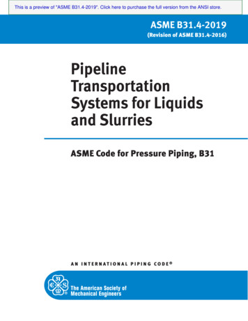
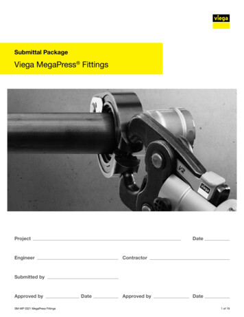
ASME B31.3 App-S Examples3. Example No.2The system is as shown in Fig. S302.1 of the code attached. This example is used mainlyto demonstrate the handling of the pipe lifted off from the supports during operation.In SIMFLEX, the situation is handled automatically just by stating the support is a singleacting support resisting the minus (-) direction movement. In this case it is described asLSY-, that is a limit stop in (-) Y- direction at point-50. To describe the system toSIMFLEX-II, the following input data file is needed:***** Input Data **********************************************ASME B31.3 EXAMPLE ANALYSIS - EXAMPLE-2APPENDIX S, S302.1*********************** COMMENTS (STARING WITH AN ASTERISK) ********************* SIMFLEX USE SG 8.03 (0.29) FOR CARBON AND LOW ALLOY STEELS** B31.3 EXAMPLE USES (0.283) 7.836** SIMFLEX DEFAULT WILL INCLUDE PRESSURE ELONGATION** B31.3 EXAMPLE DOES NOT, MANUALLY SET PELONG 2** SIMFLEX ADD 15% FOR MESH AND COVERING FOR INSULATION WEIGHT** FOR IDEN 11, SET TO 11*0.85 9.35 TO GET EQUIVALENT NUMBER AS EXAMPLE******* DISPLACEMENT STRESS RANGE ALLOWBLE** B31.3 EXAMPLE USES 302.3.5 EQ.(1a) SA f(1.25Sc 0.25Sh)** SIMFLEX DEFAULT USES EQ.(1b)SA f[1.25(Sc Sh) - SL)** TO MATCH EXAMPLE USE AN TALLOW 2 OPTION, WHICH HAS LESS ********************************OPTION, CODE 3, COMPL, TTWO, TW, AMB 70, UNTOL 12.5, PSIF, SUPPORTPELONG 2, TALLOW 2SPIPE1, D -16, THK STD, ITHK 5, MATL A106/B, SG 7.836, CSG 1.0TEMP (550, 30), P 550, CA 0.063, IDEN 9.35************10, ANCH, PIPE115, X 2020, X 20, STY30, X 10, BR40, Y 20, BR50, X 30, LSY145, X 30, BR130, Y -20, BR120, X 10, STY115, X 20110, X 20, ANCHENDThe lines starting with an asterisk are comment lines, which are not needed but are usedas comments. These data generate a system as shown on the isometric and resulting acode stress compliance chart shown in the following.7
ASME B31.3 App-S ExamplesIsometricCode Stress Compliance Chart. Sustained stress has 2 places overstress (noted with *)8
ASME B31.3 App-S Examples3A – Operating Condition Support LoadThis table shows support loads at operating condition. Special note is given to the supportat point-50, where the pipe is lifting off the support, therefore, does not provide anysupport load.123 FEB 13 PENG ENGINEERING, HOUSTON - SIMFLEX-II (RE-9.0 ) (ASME-B31.3) PAGE ------------------------------------ASME B31.3 EXAMPLE ANALYSIS - EXAMPLE-2APPENDIX S, S302.1DATA FILE : B313-S302-1.CASE 4 TH WT RESULTS****************LOAD THM,WGT,BWG,FOR,UFR,CSP,PRESMAX ECH 1.0000*** ANCHOR AND SUPPORT FORCES - INCLUDING FRICTION (ACTING ON SUPPORT) ------------------------------/------------- SUPPORT FORCE AND MOMENT -------------//--------- FRICTION ---------//---- DEFLECTION ---/SUPT DATA--- FORCES (LBS) ----- MOMENTS (FT-LBS) --- -- FORCES (LBS) -- -200320000.00.00.000STY200 -1317400000000 1.64.00.000LSY500000000000.00.77.00 INACTIVE0STY1200 -1317400000000 -1.64.00.000ANCH *************NET FORCES1-3267400000This is the operating condition when the pipe has its lowest allowable stress. Therefore,the sustained stress should be calculated under this condition with suppot-50 inactive.The support loads calculated by SIMFLEX are almost exactly the same as the ones givenby Table S302.5.1 of the code attached.9
ASME B31.3 App-S Examples3B – Sustained StressesSIMFLEX automatically inactivate support-50 resulting the sustained stresses as shownin the following table:123 FEB 13 PENG ENGINEERING, HOUSTON - SIMFLEX-II (RE-9.0 ) (ASME-B31.3) PAGE -----------------------------------ASME B31.3 EXAMPLE ANALYSIS - EXAMPLE-2APPENDIX S, S302.1DATA FILE : B313-S302-1.CASE 1 WEIGHT RESULTS****************LOAD WGT,FOR,UFR,PRESMAX ECH 1.0000*** PIPE STRESSES ------------------------MEMBER DATA PIPE CROSS SECTN-- FORCES ------ MOMENTS ---- STRESS-INTN---------- STRESSES ---------TYPEPTODAREAMODULAXIAL SHEARTORSION BENDING OUT-P IN-PHOOP LONGI TRESCA EQUIV(IN) (IN2) (IN3)(LB)(LB)(FT-LB) (FT-LB)(PSI) (PSI) (PSI) --------------------------RUN1016.00 15.3859.2 -2824187902976 1.000 1.000138837471 1389260415-2824144501368 1.000 1.000138837145 13888278RUN1516.00 15.3859.2 -2824144501368 1.000 1.000138837145 1388827820-28244770060784 1.000 1.00013883 19198 19385 12330RUN2016.00 15.3859.2 -28249689060784 1.000 1.00013883 19198 19509 1233030A-28248359011410 1.000 1.000138839182 141222315BEND30A16.00 15.3859.2 -28248359011410 1.593 1.91213883 11293 14279442530B-77233728021403 1.593 1.91213883 14850 156658301BEND30B16.00 15.3859.2 -77233728021403 1.593 1.91213883 14850 15665830130C-78372824022103 1.593 1.91213883 15114 159318573RUN30C16.00 15.3859.2 -78372824022103 1.000 1.00013883 11025 13929448440A-51772824023091 1.000 1.00013883 11399 139364684BEND40A16.00 15.3859.2 -51772824023091 1.593 1.91213883 15670 16140895640B-54731478024156 1.593 1.91213883 16064 165619369BEND40B16.00 15.3859.2 -54731478024156 1.593 1.91213883 16064 16561936940C-28244654019055 1.593 1.91213883 14258 147047390RUN40C16.00 15.3859.2 -28244654019055 1.000 1.00013883 10733 13995386550-28240046112 1.000 1.00013883 16222 163699354RUN5016.00 15.3859.2 -28240046112 1.000 1.00013883 16222 163699354145A-28244654019055 1.000 1.00013883 10733 139953865BEND 145A16.00 15.3859.2 -28244654019055 1.593 1.91213883 14258 147047390145B-54731478024156 1.593 1.91213883 16064 165619369************* Part of the table removed to fit the paper ---------------RUN12016.00 15.3859.2 -28244770060784 1.000 1.00013883 19198 19385 12330115-2824144501368 1.000 1.000138837145 13888278RUN11516.00 15.3859.2 -2824144501368 1.000 1.000138837145 13888278110-2824187902976 1.000 1.000138837471 ********************************MAXIMUM STRESSES13883 19198 19509 12330AT POINTS110120120120The sustained longitudinal stresses as shown as “LONGI” stresses are somewhat higherthan the stresses given by the code table S302.3.1 attached. This is again likely due to theconservative formula used in calculating the longitudinal pressure stress.The Fy force, 14515 lbs, on code Table S302.3.1 appears to be inconsistent. (SIMFLEXvalue is 9689 lbs)10
ASME B31.3 App-S Examples3C – Code Stress Compliance Table – Example 2123 FEB 13 PENG ENGINEERING, HOUSTON - SIMFLEX-II (RE-9.0 ) (ASME-B31.3) PAGE ------------------------------------ASME B31.3 EXAMPLE ANALYSIS - EXAMPLE-2APPENDIX S, S302.1DATA FILE : B313-S302-1.0 * EXPANSION STRESS IS THE COMBINATION OF (2) THERMAL CONDITION(S), **PLUS EARTHQUAKE SUPPORT DISPLACEMENT, IF ANY.** OCCASIONAL STRESS IS THE SUM OF SUSTAINED, GREATER OF EARTHQUAKE **INERTIA AND WIND, HARMONIC, AND OCCASIONAL FORCES, IF ANY *0*** PROCESS PIPING CODE COMPLIANCE ANALYSIS - ASME B31.3 --------/PAR.304.1.2-EQ.3/ /PAR.302.3.5, (C) / /PAR.302.3.6, (A) / /PAR.302.3.5, (D) /MEMBER DATA PSI)EXPANSION-(PSI)TYPEPTODTHKDESIGNALLOW CALCULATED ALLOW CALCULATED ALLOW CALCULATED ----------0 RUN10 16.00 .37555060874711809974712407229552952415 16.00 .3755506087145180997145240721496295240 RUN15 16.00 .37555060871451809971452407214962952420 16.00 .37555060819198OVER 1809919198240725946295240 RUN20 16.00 .37555060819198OVER 18099191982407259462952430A 16.00 .3755506089182180999182240726363295240 BEND30A 16.00 .37555060811293180991129324072162202952430B 16.00 .3755506081485018099148502407215498295240 BEND30B 16.00 .37555060814850180991485024072154982952430C 16.00 .3755506081511418099151142407213379295240 RUN30C 16.00 .3755506081102518099110252407252482952440A 16.00 .375550608113991809911399240724502295240 BEND40A 16.00 .37555060815670180991567024072114752952440B 16.00 .3755506081606418099160642407213594295240 BEND40B 16.00 .37555060816064180991606424072135942952440C 16.00 .3755506081425818099142582407214317295240 RUN40C 16.00 .3755506081073318099107332407256162952450 16.00 .375550608162221809916222240724969295240 RUN50 16.00 .37555060816222180991622224072496929524145A 16.00 .37555060810733180991073324072561629524********* Part of the table removed to fit the page ---0 BEND 130B 16.00 .375550608148501809914850240721549829524130C 16.00 .3755506081129318099112932407216220295240 RUN130C 16.00 .375550608918218099918224072636329524120 16.00 .37555060819198OVER 1809919198240725946295240 RUN120 16.00 .37555060819198OVER 180991919824072594629524115 16.00 .3755506087145180997145240721496295240 RUN115 16.00 .375550608714518099714524072149629524110 16.00 ------------------------------------------OVER STRESS POINTS:0400*** OVER STRESS AT4 LOCATIONSThe sustained stress has two overstress points (4 ends) in this piping system. Thecalculated stress is somewhat higher than the ones given by the Table S302.6.3.1 of thecode attached. The difference 19198 psi (SIMFLEX) vs. 18850 psi (Code Book) is about2%.11
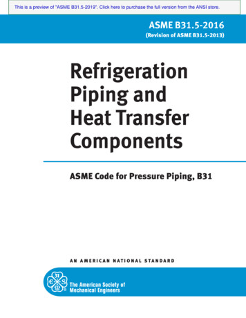
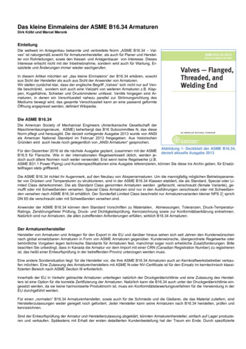
ASME B31.3 App-S Examples4. Example No. 3The system is as shown in Fig. S303.1 of the code attached. This example is used mainlyto demonstrate the treatment of moment reversal between different operating conditions.This simple loop system has two alternate operating condition. The moment generated inone condition is the same but in opposite direction of the other condition.In SIMFLEX, the operation conditions are assigned as T-1 and T-2 without combiningthe sustained load, and TW-1 and TW-2 to include the sustained loads. To describe thetwo operating conditions, the pipe is separated into Pipe1 for the header with temperaturethe same at 250-F for both operating conditions; Pipe2 for the East branch havingambient temperature for the first operating condition and 250-F temperature at secondoperating condition; and Pipe3 for West branch with 250-F for the first operating andambient for the second operating condition. These temperatures are described asTEMP(t1, t2, t3, )To describe the system to SIMFLEX-II, the following input data file is needed:*** Input Data ***************************ASME B313 EXAMPLE ANALYSIS - EXAMPLE-3EXAMPLE 3: MOMENT REVERSAL*********** COMMENTS (STARTING WITH AN ASTERIK) ***************************** ALLOWABLE FOR DISPLACEMENT STRESS RANGE :*** SIMFLEX DEFAULT USES EQ.(1b):SA f[1.25(Sc Sh) - SL]*** B31.3 EXAMPLE ALSO USES EQ.(1b) FOR POINTS 20 AND 220******** THE USE OF f 1.2 IS NOT RECOMMENDED, BUT USED HERE TO ***********************OPTION, CODE 3, COMPL, TTWO, TW, UNTOL 12.5, AMB 40, PELONG 2F 1.2*********SPIPE1, D -24, THK STD, MATL A53/B/S, TEMP (250, 250), P 300CSG 0.0, CLASS 300SPIPE2, D -20, THK STD, MATL A53/B/S, TEMP (40, 250), P 300CSG 0.0, CLASS 300SPIPE3, D -20, THK STD, MATL A53/B/S, TEMP (250, 40), P 300CSG 0.0, CLASS 300*********10, ANCH, PIPE120, X 5, TEE30, Z 5, TEE35, Z 2.540, FROM 20, Z -5, TEE45, Z -2.5*********** EAST BRANCH*********12
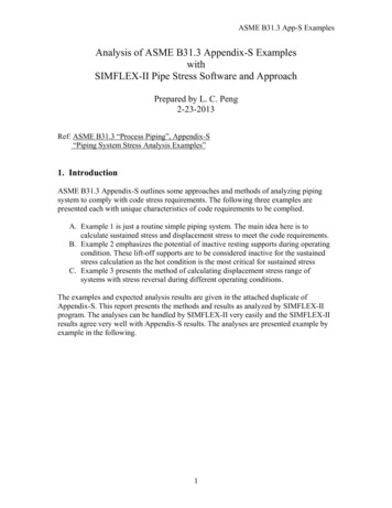
ASME B31.3 App-S Examples110, FROM 40, PIPE2, X 5, STY120, X 5130, X 5, GTV(2000, 5, 1000)140, X 5, STY340, X 5, TEE*********** WEST BRANCH*********210, FROM 30, PIPE3, X 5, STY220, X 5230, X 5, GTV(2000, 5, 1000)240, X 5, STY330, X 5, TEE*********** SOUTH HEADER*********335, FROM 330, Z 2.5, PIPE1***320, FROM 330, Z -5, TEE, PIPE1340, Z -5345, Z -2.5310, FROM 320, PIPE1, X 5.0, STY, STZ, SRX, SRY, SRZENDThe lines starting with an asterisk are comment lines, which are not needed but are usedas comments. The valve is modeled as 1000 times as stiff as the connecting pipe of thesame length. This is SIMFLEX default for rigid bodies. SIMFLEX default stiffness forvalves is 3 times as stiff as the pipe. These data generates a system as shown on theisometric and resulting a code stress compliance chart shown in the following.13
ASME B31.3 App-S ExamplesIsometricCode Stress Compliance Chart. Displacement (Expansion) has two over stress locations14
ASME B31.3 App-S Examples4A – First Condition Displacement Stress124 FEB 13 PENG ENGINEERING, HOUSTON - SIMFLEX-II (RE-9.0 ) (ASME-B31.3) PAGE ------------------------------------ASME B313 EXAMPLE ANALYSIS - EXAMPLE-3EXAMPLE 3: MOMENT REVERSALDATA FILE : B313-S303-1.CASE 2 THERMAL RESULTS****************LOAD THM,BWG,MAX ECH 1.0000*** PIPE STRESSES ------------------------MEMBER DATA PIPE CROSS SECTN-- FORCES ------ MOMENTS ---- STRESS-INTN---------- STRESSES ---------TYPEPTODAREAMODULAXIAL SHEARTORSION BENDING OUT-P IN-PHOOP LONGI TRESCA EQUIV(IN) (IN2) (IN3)(LB)(LB)(FT-LB) (FT-LB)(PSI) (PSI) (PSI) 66136613661RUN13020.00 23.12 111.3 176370033973 1.000 1.0000442444243661140176370033973 1.000 1.0000442444243661RUN14020.00 23.12 111.3 176370033973 1.000 1.0000442444243661340176370033973 4.145 3.3540 13044 13044 12281********** Part of the table removed to fit the page ------------------RUN3020.00 23.12 111.3 -176370033973 4.145 3.3540 13044 13044 12281210-176370033973 1.000 1.0000442444243661RUN21020.00 23.12 111.3 -176370033973 1.000 1.0000442444243661220-176370033973 1.000 23.1220.0023.1224.0027.83111.3 -17637-17637111.3 13044003661366136611228100RUN32024.00 27.83 161.9000108429 4.223 3.4170 27468 27468 27468310000108429 1.000 ******************************************MAXIMUM STRESSES0 27468 27468 27468AT POINTS310320320320The displacement stress given as “EQUIV” stresses agree very well with the code stressgiven in Table S303.7.1 attached. However, since the bending moment normally is thecombination of the in-plane and out-plane moments that the sign is lost in this table. Themoment component sign in the next table should be used to calculate the stress range.This is done automatically in SIMFLEX.15
ASME B31.3 App-S Examples4B – Displacement Forces, Moments, and Displacements for First Operating Condition124 FEB 13 PENG ENGINEERING, HOUSTON - SIMFLEX-II (RE-9.0 ) (ASME-B31.3) PAGE ------------------------------------ASME B313 EXAMPLE ANALYSIS - EXAMPLE-3EXAMPLE 3: MOMENT REVERSALDATA FILE : B313-S303-1.CASE 2 THERMAL RESULTS****************LOAD THM,BWG,MAX ECH 1.0000*** MEMBER FORCES (ACTING ON PIPE) AND DISPLACEMENT -----------------------------MEMBER DATA----- FORCES (LBS) -------- MOMENTS (FT-LBS) ---DISPLACEMENTS (IN)ROTATION 17638000-339740-.017.000.121.000 -.085.000210-17638000339740.062.000.188.000 -.043.000RUN21017638000-339740.062.000.188.000 .000.188.000.043.000********** Part of table removed to fit the page 041.000.078.000340-17638000-339740.184.000 -.040.000.085.000RUN340000000.184.000 -.040.000.085.000345000000.139.000 .078.0003100000 *********MAXIMUM RESPONSE176370001084290.423.000.210.000.085.000AT POINTS33031020310320310335310230310335310At the critical stress location point-20 end, the moment sign is (-). The sign of secondoperating condition shall be checked to determine the stress range calculated by takingthe difference.16
ASME B31.3 App-S Examples4C – Displacement Stress of the Second Operating Condition124 FEB 13 PENG ENGINEERING, HOUSTON - SIMFLEX-II (RE-9.0 ) (ASME-B31.3) PAGE ------------------------------------ASME B313 EXAMPLE ANALYS
Feb 23, 2013 · ASME B31.3 App-S Examples 1 Analysis of ASME B31.3 Appendix-S Examples with SIMFLEX-II Pipe Stress Software and Approach Prepared by L. C. Peng 2-23-2013 Ref: ASME B31.3 “Process Piping”, Appendix-S “Piping System Stress Analysis Examples” 1. Introduction ASME B31.3 Appen