Transcription
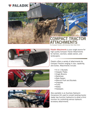
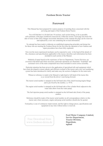
CONNECTING IMPLEMENTS TOTHE TRACTORHOSTA Task Sheet 5.1CoreNATIONAL SAFE TRACTOR AND MACHINERY OPERATION PROGRAMIntroduction“The owner says that I should beable to connect (hitch) the rake tothe tractor and be in the nearbyfield within 5 minutes. It has been10 minutes, and I still can’t seemto get the drawbar of the tractorlined up with the hitch on therake.”Can you steer in reverse? Can youuse the clutch and brakessmoothly? If not, review thelessons on steering in reverse andmoving and steering the tractor.Do you understand where to hitchto the load to insure tractorstability? If not, review the lessonson tractor stability.This task sheet provides anoverview of safe and efficienthitching of implements to thetractor. See Task Sheet 5.2 or 5.3for additional details.Angle of PullCenter of GravityFigure 5.1.a. An example of safe hitching.The drawbar will lower if the front end liftsoff the ground. This reduces the “angle ofpull” and the risk of a rear overturn.Pulling a load with the downwardand rearward force above thetractor’s center of gravity willresult in a rear overturn. You musthitch only to the drawbar toprevent the tractor from rearing upand turning over. Even small lawnand garden-size tractors can fliprearward if not properly hitched toa load.Figure 5.1.c. The tractor drawbar is the only safeplace to connect a load. Do not hitch higher thanthe drawbar so all pulling forces stay below thetractor’s center of gravity. For most operations,the drawbar should be placed midpoint betweenthe rear tires to maximize pulling power. Hillsideoperations may require a drawbar adjustment toone side to balance the pulling forces.Hitch to the drawbaronly! Hitchinganywhere else canresult in rear turnoverand death.Hitching and theCenter of GravityLearning Goals To safely connect an implement tothe tractor’s drawbarIn Task Sheet 4.12, TractorStability, you learned about thetractor’s center of gravity andstability baseline. Tractor hitchesare designed so the downward andrearward force during a pull arebelow the center of gravity (seeFigure 5.2.a.). To maintain tractorstability, the “angle of pull” shouldbe kept as low as possible byhitching to the drawbar only. To safely connect an implement tothe tractor’s 3-point hitchRelated Task Sheets:Figure 5.1.b. The log is fairly immovable.A chain hooked above the center ofgravity of the tractor (e.g., top of 3-pointhitch bracket), allows a rearward tip ofthe tractor. Improper hitching hasoverridden safe tractor engineeringdesign. Many people have lost their livesas a result. Safety Management for Landscapers,Tractor Stability4.12Using the Tractor Safely4.13Operating the Tractor on PublicRoads4.14Using Drawbar Implements5.2Using 3-Point Hitch Implements5.3Grounds-Care Businesses, and Golf Courses, JohnDeere Publishing, 2001. Illustrations reproduced bypermission. All rights reserved. The Pennsylvania State University 2004Cooperation provided by The Ohio State University and National Safety Council.
Page 2CONNECTING IMPLEMENTS TO THE TRACTORDPTOBFigure 5.1.d. Tractor drawbars aredesigned at the correct height fromthe ground to keep the pull forcesbelow the center of gravity. Onlyuse the drawbar to tow a load. Aswinging or floating drawbarpermits adjustment of the centerline of pull to be maintained evenon a hillside.DrawbarCAFigure 5.1.e. The tractor power take-off and drawbar position are designed with specificmeasurements for the size and horsepower rating of the tractor. The operator should notmake changes to these design standards by changing the hitch point. Table 5.1.a lists themeasurements and relationships at points A, B, C, and D above for each range of tractorsize.Drawbar Hitch CategoryA bolt layingaround thefarm shop isnot asubstitutehitch pin!Hitch pins aredesigned forspecificdrawbar loadsand powerratings andmust fit thedrawbar hole.ItemTractor HPIII20-4540-100IIIIV80-275180-400Drawbar Heightabove ground (A)15" /-2"15" /-2"19" /-2"19" /-2"Drawbar to PTO (B)8"-12"8" - 12.5"8.5" -14"10" -14"1.1"1.3"1.7"Hitch-Pin Hole Size(C)*Nominal Hitch Pin Size*1.0"1.2"1.6"Drawbar Dimensions(Thickness x width) 1-3/16"x2.0" 1-9/16"x2.5" 2"x 3-3/16"Regular Size PTOStub Shaft to DrawbarHitch Hole (D)14-20"14-20"14-20"2.1"2.0"2-3/8"x 4-7/8"14-20"* The measurement has been rounded to the nearest 1/10 (0.1) inch.Hitch pins must fit the hitch-pin hole without excessive movement.Table 5.1.a. Drawbar Sizing and Positioning Standards (ASAE S482) The Pennsylvania State University 2004Cooperation provided by The Ohio State University and National Safety Council.
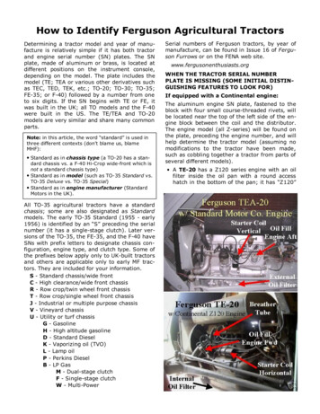
Page 3HOSTA TASK SHEET 5.1The 3-Point HitchFEABFigure 5.1.g. Never let another person stand betweenthe tractor and the implement during hitching. Too fastof an approach or the operator’s foot slipping from theclutch can lead to injury or fatality to the personstanding nearby. Safety Management for Landscapers, GroundsCare Businesses, and Golf Courses, John Deere Publishing, 2001.Illustrations reproduced by permission. All rights reserved.CDto match the implement hitchpoints.4. Stop the engine, securely parkthe tractor, set the brakes.Figure 5.1.f. Parts of the 3-Point HitchA.Upper LinkB,C. Draft ArmsE.Lift ArmF. Lift RodD. Anti-sway bar or chainSafety Management for Landscapers, Grounds-Care Businesses, and Golf Courses, John DeerePublishing, 2001. Illustrations reproduced by permission. All rights reserved.blocks from the wheels.5. Connect the PTO shaft,Implement Hitchinghydraulic hoses, and/orFollow these steps for hitching toelectrical connections asa drawbar: Also see Task Sheetrequired. Refer to the5.2.appropriate task sheets on1. Position the tractor to align thethese subjects.hole in the drawbar with theFollow these steps for hitching tohole in the implement hitch.a 3-point hitch attachment: AlsoThis is called spotting. Youmay need to practice this skill. see Task Sheet 5.3.2. Stop the engine, put the tractor 1. Move the stationary tractordrawbar forward forin park, and set the brakes.clearance.3. Attach the implement usingthe proper-sized hitch pin and 2. Position the tractor so the pinholes of the draft arms aresecurity clip.closely aligned with the4. Raise the implement jackimplement hitch points.stand and remove chock3. Raise or lower the draft arms The Pennsylvania State University 20045. Attach each draft arm to theimplement hitch point usingthe proper size hitch pin andsecurity clip.6. Remount and start the tractorto use the hydraulic system toraise the lift arms if needed.7. Match the upper link of the 3point hitch to the implement’supper hitch point. The upperlink is adjustable by screwthreads to make the finalconnection. The implementmay not be level if the upperlink has been adjusted toomany times. If it is out oflevel, the machine may notwork properly If you cannotlevel the machine, ask forhelp.8. Securely attach the upperhitch pin with the proper sizehitch pin and security clip.Cooperation provided by The Ohio State University and National Safety Council.
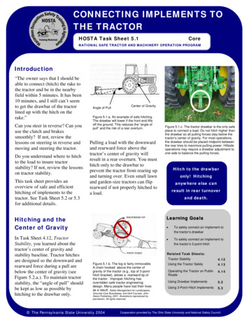
Page 4CONNECTING IMPLEMENTS TO THE TRACTORUpper HookLower HookLatchLower HooksFigure 5.1.h. Tractors equipped with quick-attach couplershave hooks which must be latched to lock the implementinto place. If you have never used one of these quick-attachcouplers, have a qualified operator demonstrate the correctprocedure or find the information in the Owner’s Manual.Figure 5.1.i. Heavy-duty quick-attach couplers are mounted onto the tractor’s 3-pointhitch and can safely handle large 3-point hitch implements without a person movingbetween the tractor and the implement. See the circled areas which show these hookand latch points. Refer to the Owner’s Manual for additional instructions on their use.Safety Activities1. Practice backing a tractor with a drawbar to an implement to “spot” the hole in the drawbar to the hole in theimplement tongue. You should be able to perform this skill with a minimum number of changes of directionto be a proficient tractor operator.2. Practice backing a tractor with a 3-point hitch to an implement to adjust the pin hole in the draft arms to thelower hitch pins on the implement’s 3-point hitch attachment. As you become more able to align thesepoints, securely park the tractor. Attach the draft arm hitch pins, restart the tractor, adjust the draft arms toalign, and connect the upper link point. You should be able to perform this skill with a minimum change ofdirection to be a proficient tractor operator.3. On a tractor you can easily measure, take measurements and record the following:a. distance from ground to drawbar inchesb. dimensions of drawbar (width and thickness) x inchesc. hitch-pin hole opening in drawbar inchesd. vertical distance from drawbar to center of PTO stub shaft inchesHow do these measurements compare with the standards shown on Table 5.2a?4. Using a battery-operated toy truck or tractor, devise a place to hitch a load at a point above the toy’s axle.Make a sled from sheet metal or cardboard, and attempt to pull a load of small objects such as nuts, bolts,etc. What happens as the toy attempts to pull the load? Change the height and length of the angle of pull,and record the reaction of the toy truck or tractor to the changes made.References1.www.asae.org/Click on Technical Library/FindStandards on pull down menu/Type in Drawbars,Download PDF for S482, December 1998.2.www.asae.org/Click on Technical Library/FindStandards on pull down menu/Type in Three-PointFree Link Attachment, Download PDF for S217,December 2001.3.Safety Management for Landscapers, Grounds-CareBusinesses, and Golf Courses, John Deere Publishing,2001. Illustrations reproduced by permission. All rightsreserved. The Pennsylvania State University 2004Contact InformationNational Safe Tractor and Machinery Operation ProgramThe Pennsylvania State UniversityAgricultural and Biological Engineering Department246 Agricultural Engineering BuildingUniversity Park, PA 16802Phone: 814-865-7685Fax: 814-863-1031Email: NSTMOP@psu.eduCreditsDeveloped, written and edited by WC Harshman, AM Yoder, JW Hilton and D J Murphy,The Pennsylvania State University. Reviewed by TL Bean and D Jepsen, The Ohio StateUniversity and S Steel, National Safety Council.Version 4/2004This material is based upon work supported by the Cooperative State Research, Education, and ExtensionService, U.S. Department of Agriculture, under Agreement No. 2001-41521-01263. Any opinions, findings,conclusions, or recommendations expressed in this publication are those of the author(s) and do notnecessarily reflect the view of the U.S. Department of Agriculture.Cooperation provided by The Ohio State University and National Safety Council.
USING POWER TAKE-OFF (PTO)IMPLEMENTSHOSTA Task Sheet 5.4.1CoreNATIONAL SAFE TRACTOR AND MACHINERY OPERATON PROGRAMIntroductionThe power take-off (PTO) shaft, orImplement Input Driveline (IID), isan efficient means of transferringmechanical powerbetween farm tractorsand implements. Thispower transfer systemhelped torevolutionize NorthAmerican agricultureduring the 1930s. ThePTO is also one of theoldest and mostpersistent hazardsassociated with farmmachinery. This tasksheet discussesseveral aspects ofPTO safety.PTO ComponentsFigure 5.4.1.a. is a diagram of thecomponents of an implement PTOsystem. Two typical PTO systemarrangements are shown. The topdrawing is of a PTO systeminvolving a pedestal connection,such as one found on many types oftowed implements (hay balers,forage choppers, large rotarymowers, etc.). The lower drawingis of a PTO system where theimplement’s input drivelineconnects directly to the tractor PTOstub. Examples of this type ofconnection include three-pointhitch-mounted equipment, such aspost hole diggers, small rotaryFigure 5.4.1.a. The major components of a PTO system.mowers, fertilizer spreaders, andaugers.Connections from the tractor tothe implement are made throughthe flexible universal joints. The“U-joints” are connected by asquare rigid shaft which turnsinside another shaft. The PTOshaft can telescope in and out foruse in turns or over uneventerrain.The combination of universaljoints and turning shafts providesthe remote power source to afarm implement. Without properguarding, a serious threat to theoperator’s safety is created.Study this task sheet carefully. The Pennsylvania State University 2004Learning Goals To identify the components of a PTOsystem To identify the hazards involved withPTO use To develop safe habits when using aPTORelated Task Sheets:Reaction Time2.3Mechanical Hazards3.1Making PTO Connections5.4Cooperation provided by The Ohio State University and National Safety Council.
USING POWER TAKE-OFF (PTO) IMPLEMENTSPage 2PTO Stub Transfers power from the tractor to the machineRotates at 540 rpm (9 times/sec.) or at 1,000 rpm (16.6times/sec.)Master Shield Protects the operator from the PTO stub Is often damaged or removed and never replaced.Figure 5.4.1.b. The major components of a PTO system found on the tractor.the casesThe PTO is oneof the oldest andmost persistenthazardsassociated withPTO Entanglement This information is taken from thePurdue University source listed atthe end of this fact sheet. Thisreference is the mostcomprehensive study of powertake-off injury incidents to date.The data shown includes fatal andnonfatal injury incidents.Generally, PTO entanglements:occurred with stationaryequipment, such as augers,elevators, post-hole diggers,and grain mixers in 50 percentof the cases involved semi-stationaryequipment, such as selfunloading forage wagons andfeed wagons in 28 percent ofthe cases happened mostly with incidentsinvolving non-movingmachinery, such as hay balers,manure spreaders, rotarymowers, etc., at the time of theincident (the PTO was leftengaged). occurred 4% of the time whenno equipment was attached tothe tractor. This means thetractor PTO stub was the pointof contact at the time of theentanglement. involved the tractor ormachinery operator 78 percentof the time occurred when shielding wasabsent or damaged in 70percent of the cases were at the PTO coupling,either at the tractor orimplement connection nearly70 percent of the time involved a bare shaft, springloaded push pin, or throughbolt component at the point ofcontact in nearly 63 percent offarm machinery. The Pennsylvania State University 2004Cooperation provided by The Ohio State University and National Safety Council.
Page 3HOSTA TASK SHEET 5.4.1PTO GuardsMaster Shield Implement Input Connection (IIC)Shield Protects the operator fromthe IIC, including theimplement input stub andthe connection to the IIDProtects the operatorfrom the PTO stuband the connection ofthe IID to the PTOstubIntegral Journal ShieldSafety Chain Keeps the integral journalshield from spinning Shows that the shield is notattached to the IID Should be replacedimmediately if damaged orbroken Figure 5.4.1.c. The major guards of a PTO system.recommended for yourmachine. Never switchdrivelines among differentmachines.PTO Safety PracticesThere are several ways to reducethe risk of PTO injuries andfatalities. These safety practicesoffer protection from the mostcommon types of PTOentanglements. Keep all components of PTOsystems shielded and guarded. Regularly test driveline guardsby spinning or rotating them toensure they have not becomestuck to the shaft. Disengage the PTO and shutoff the tractor beforedismounting to clean, repair,service, or adjust machinery. Walk around tractors andmachinery rather than steppingover a rotating shaft. Always use the driveline Position the tractor’s drawbarproperly for each implementused. This will help preventdriveline stress and separationon uneven terrain and in tightturns. See Task Sheet 5.1.Reduce PTO shaft abuse byobserving the following: avoidtight turns that pinch rotatingshafts between the tractor andmachine; keep excessivetelescoping to a minimum;engage power to the shaftgradually; and avoid overtightening of slip clutches onPTO-driven machines. The Pennsylvania State University 2004Completely enclosesthe IIDMay be made ofplastic or metalMounted on bearingsto allow it to spinfreely from the IIDAlways check beforeoperation for freemovementIf PTO guards areremoved ordamaged, theyshould be replacedimmediately.Figure 5.4.1.d. A bent shaft guard offers noprotection from a spinning PTO shaft. Alsonotice the missing master shield and theinadequate guarding of the universal joint nearthe PTO pedestal.Cooperation provided by The Ohio State University and National Safety Council.
Page 4HOSTA TASK SHEET 5.4.1PTO Safety Activities1. Fill in the blanks in the following figure of the major components of a PTO system based on theinformation in this sheet.2. You are working with another tractor operator. He/she is sitting on the tractor seat and is able to reach thePTO control. If your shoelace is caught in the PTO shaft, how long does the shoelace need to be in order forthe tractor operator to have enough time to shut off the PTO before your foot is pulled into the PTO shaft?The PTO shaft is spinning at 540 rpms, the shaft diameter is 3 inches (d), and the operator can react byshutting off the PTO in 3 seconds.2c. 27 revolutions in 3seconds2b. 9 revolutions persecond2a. 9.42 inchesb. How many times does the PTO shaft rotating 540 revolutions per minute rotate in onesecond?540 revolutions x 1 Min 540 revolutions revolutions1 Min60 sec60 secsec2d. 254.34 inches or21.20 feeta. Find the circumference of the PTO shaft.Circumference π d 3.14 x 3 inches inches1. See Figure 5.4.aPTO Safety ActivityAnswersc. How many times does the PTO shaft rotate in 3 seconds?Answer b x 3 sec revolutionsd. How much shoelace will become wrapped up in the PTO in 3 seconds?Answer a (in inches) x Answer c (in revolutions) inches of shoelace.References1.Campbell,W.P.1987.The Condition of Agricultural DrivelineSystem Shielding and Its Impact in Injuries andFatalities.M.S.Thesis.Department ofAgriculturalEngineering,Purdue University,WestLafayette,IN.2.Farm and Ranch Safety Management, John Deere Publishing,1994.3.Murphy, D.J. 1992 Power Take-Off (PTO) Safety. Fact SheetE-33. The Pennsylvania State University. University Park, PA.4.Safe Operation of Agricultural Equipment:StudentManual.1988,Revised.Hobar Publications,St.Paul, MN. The Pennsylvania State University 2004Contact InformationNational Safe Tractor and Machinery Operation ProgramThe Pennsylvania State UniversityAgricultural and Biological Engineering Department246 Agricultural Engineering BuildingUniversity Park, PA 16802Phone: 814-865-7685Fax: 814-863-1031Email: NSTMOP@psu.eduCreditsDeveloped, written and edited by WC Harshman, AM Yoder, JW Hilton and D J Murphy,The Pennsylvania State University. Reviewed by TL Bean and D Jepsen, The Ohio StateUniversity and S Steel, National Safety Council.Version 4/2004This material is based upon work supported by the Cooperative State Research, Education, and ExtensionService, U.S. Department of Agriculture, under Agreement No. 2001-41521-01263. Any opinions, findings,conclusions, or recommendations expressed in this publication are those of the author(s) and do notnecessarily reflect the view of the U.S. Department of Agriculture.Cooperation provided by The Ohio State University and National Safety Council.
and garden-size tractors can flip rearward if not properly hitched to a load. Introduction Figure 5.1.c. The tractor drawbar is the only safe place to connect a load. Do not hitch higher than the drawbar so all pulling forces stay below the tractor’s center of gravity. For most