Transcription
Introduction to Data CenterTop of Rack (ToR) Architecture DesignJanuary 15, 2009Cisco Systems, Inc.3 West Plumeria DriveSan Jose, CA 95134
Introduction to Data Center Top of Rack (ToR) Architecture DesignTable of ContentsPreface. 2Introduction . 2Top-of-the-Rack Architecture Drivers . 3Modular Data Center Infrastructure . 4The Pod Approach . 6Top of Rack Access Media Considerations. 7Fiber and Copper Cabling Characteristics . 8Fiber . 9Copper . 10Top-of-the-Rack Cabling Recommendations. 10Top-of-the-Rack Model at Work with the Nexus 5000 and 2000 . 11Top of the Rack in Gigabit Ethernet Environments . 11Summary. 14-1-
PrefaceForward-looking IT departments are preparing their data centers for the future by integrating support for 10 GigabitEthernet and a Unified Network Fabric into their switching and cabling strategies. Since the typical data center lifecycle is 10-15 years, structured cabling architectures have a tremendous impact on the data center’s ability to adapt tonetwork architecture changes, bandwidth and moves, adds, and changes (MACs). Cabling architectures, if not chosencorrectly, could force an early replacement of the cabling infrastructure to meet connectivity requirements as thenetwork and computer technologies evolve.There are multiple cabling models and architectures deployed in today’s data center. With the migration from 1GE to10GE, cabling and network switching architectures are being reevaluated to ensure a cost-effective and smooth datacenter transition. The choice of cabling architecture will impact throughput, expandability, sustainability, optimumdensity, energy management, total cost of ownership (TCO) and return on investment (ROI). Anticipating growth andtechnological changes can be somewhat of a crystal ball prediction. The data center will take on a life of its own andshould be able to respond to growth and changes in equipment, standards and demands all while remaining manageableand reliable.This paper provides a look at the use of top-of-rack (ToR) cabling and switching model for next-generation data centerinfrastructure. The paper explores current 10G cabling choices and provides a solution architecture based on ToR toaddress architecture challenges. Data center managers and facilities folks will choose cabling architectures based onvarious factors. The ToR model offers a clear access layer migration path to an optimized high-bandwidth network andcabling facilities architecture that features low capital and operating expenses and supports a rack-and-roll computerdeployment model that increases business agility. The data center’s access layer, or equipment distribution area (EDA),presents the biggest challenge to managers as they choose a cabling architecture to support the data center computerconnectivity needs. The ToR network architecture and cabling model, propose to use fiber as the backbone cabling tothe rack with different copper and fiber media for server connectivity at the rack level.IntroductionThe data center landscape is changing rapidly. IT departments building new data centers, expanding existing data centerfootprints, or updating racks of equipment all have to design a cabling and switching architecture that supports rapidchange and mobility, and accommodate transitions to 10, 40 and 100-Gbps Ethernet over time. Key drivers of thechanging landscape are: Modularity and flexibility is of paramount importance. The need to rapidly deploy new applications andeasily scale existing ones has caused server-at-a-time deployment to give way to a rack-at-a-time model. ManyIT departments are ordering preconfigured racks of equipment with integrated cabling and switching, and asmany as 96 servers per rack. The time required to commission new racks and decommission old ones is now amatter of hours rather than days or weeks. Because different racks have different I/O requirements, data centerswitching and cabling strategies must support a wide variety of connectivity requirements at any rack position. Bandwidth requirements are increasing. Today’s powerful multi-socket, multi-core servers, blade systems,and integrated server and rack systems, often running virtualization software, are running at higher utilizationlevels and impose higher bandwidth demands. Some server racks are populated with servers requiring betweenfive and seven Gigabit Ethernet connections and two Fibre Channel SAN connections each-2-
I/O connectivity options are evolving. I/O connectivity options are evolving to accommodate the need forincreasing bandwidth, and good data center switching and cabling strategies need to accommodate allconnectivity requirements at any rack position. Racks today can be equipped with 1 or 10 Gigabit Ethernet or aunified network fabric with Fibre Channel over Ethernet (FCoE). Virtualization at every layer of the Data Center. Server virtualization is driving server consolidation, greaterbandwidth and access to network attached storage. Virtualization is one of the hottest areas for the IT decisionmakers. Estimates suggest that the server virtualization market will grow by 44% over the next four years. Thischange is often disruptive and necessitates a redesign of the networking infrastructure to realize all the benefitsof the virtualized computer platform.The challenge facing data centers today is how to support the modularity and flexibility that is needed to promotebusiness agility and maintain a company’s competitive edge. The same strategy that allows the intermixing of differentrack types and I/O requirements must also support a varied set of connectivity options, including 1- and 10-GigabitEthernet, as well as unified network fabric.Top-of-the-Rack Architecture DriversRapidly changing business requirements impose a corresponding need for flexibility and mobility in data centers. Dueto the significant cost of building a new data center, designing an infrastructure that provides the flexibility to meetbusiness objectives while maximizing return on investment is an IT imperative. By building the data centerinfrastructure – power and cooling, cabling, etc -- in a modular fashion, data center flexibility can be increased, which inturn improves business agility.Many organizations are now deploying modular data centers. IT departments are increasingly deploying not just servers,but racks of servers at a time. Racks of servers, blade systems, and integrated rack-and-blade systems are oftenpurchased in preconfigured racks with power, network, and storage cabling preinstalled so that racks can becommissioned hours, not days, from the time they arrive on the loading dock. While server form factors are evolving,and some racks can host up to 96 independent computer resources, the rack form factor remains constant, making it thestandard unit of deployment in many data centers.TOR solutions compliment rack-at-a-time deployment by simplifying and shortening cable runs and easing thereplication of rack configurations. This “rack-and-roll” deployment model offers a solution by placing switchingresources into each rack so that server connectivity can be aggregated and interconnected with the rest of the data centerthrough a small number of cables connected to end-of-row access or aggregation-layer switches.The TIA 942 specification provides a simple reference for data center cabling that supports different cabling schemes –end-of-row or top-of-rack – to meet differing needs from a physical and operational perspective. One model, top-of-rackdefines an architecture where servers are connected to switches that are located within the same or adjacent racks, andwhere these switches are connected to aggregation switches typically using horizontal fiber optic cabling.Top-of-rack switching allows oversubscription to be handled at the rack level, with a small number of fiber cablesproviding uniform connectivity to each rack. The beauty of this solution is that horizontal fiber can support different I/Oconnectivity options, including 1- and 10-Gigabit Ethernet as well as Fibre Channel. The use of fiber from each rack isalso a form of future-proofing as evolving standards, including 40- and 100-Gbps Ethernet, are more likely to beimplemented using fiber before any other transmission mechanism. By limiting the use of copper to within racks, theToR model isolates the cabling that changes most often to the parts of the data center that change most frequently: theracks themselves. By using fiber runs from racks, a flexible data center cabling infrastructure that supports the transition-3-
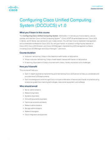
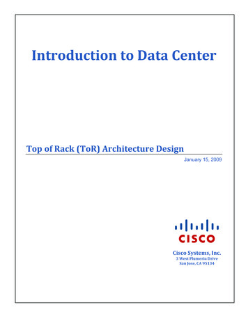
from 1- to 10-Gigabit Ethernet now, while providing a future-proof solution that enables transition to 40- and 100-GbpsEthernet in the future.Modular Data Center InfrastructureThe cabling and infrastructure design for a modern data center will be governed by multiple factors. The TIA/EIA-942Telecommunications Infrastructure Standard for Data Centers provides guidelines on data center cabling infrastructurethat customers may adopt as a guide in the DC cabling and planning process. There are other standards, like BICSI, thatprovide guidelines in DC cabling and implementation. The TIA/EIA-942 cabling specification considers the need forflexibility, scalability, reliability and space management (www.tiaonline.org). While the standard provides guidelines,there are specific design elements that will vary with each data center cabling requirement. General considerations thatapply to all data centers include: Support for storage devices (i.e. Fibre channel, SCSI or NAS, FCoE) Support for convergence/Unified Fabric with growth factors incorporated Reliability, scalability and redundancy High-capacity and high-density server access requirements Flexibility and expandability with easy access for moves, adds and changes Migration consideration for 1GE to 10GE server connectivity with future-proofing to support 40G and 100G. Cabling architecture balance with power, cooling, structural loading, management and operationsIn the context of the TIA-942 data center simplified logical layout, the ToR architecture will map directly to theEquipment Distribution Area (EDA) and the Horizontal Distribution Area (HDA). The diagram below illustrates amapping of the logical network architecture to the physical infrastructure.-4-
TIA-942 Logical LayoutEIA/TIA 568 Copper & Fiber CablingAccessProvidersOffices, OperationsCenter, SupportRoomsHorizontal CablingTelecom RoomAccessProvidersEntrance Room(Carrier Equip &Demarcation)Core / EoR AggBackbone CablingComputerRoomMain Dist AreaBackbone Cabling(Routers/BackboneLAN/SAN Switches,PBX, M13 Muxes)(Office & OperationsCenter LAN Switches)Backbone CablingFIberHoriz Dist Area(LAN/SAN/KVMSwitches)Horizontal CablingZone Dist AreaHorizontal CablingEoR Access / ToR AggHoriz Dist AreaHoriz Dist AreaHoriz Dist g ?HorizontalCablingToREquipment DistAreaEquipment DistAreaEquipment DistAreaEquipment DistArea(Rack / Cabinet)(Rack / Cabinet)(Rack / Cabinet)(Rack / Cabinet)Fig. 1.1The equipment distribution area (EDA) in the TIA-942 logical layout would correspond to the area where server racksare placed. Traditional structured copper cabling with a mix of fiber if needed for SAN or high speed serverconnectivity would be used to connect the EDA to the HDA. The environment would require careful planning to ensurethat the structured cabling will meet the initial design requirements with enough room for growth. In the cases whereserver racks were not yet in place or the physical infrastructure needed to support rack level flexibility, a ZoneDistribution Area cabling model would be used. The zone distribution area allows for structured cabling to be placedunder floor or above rack in anticipation of future server racks requiring connectivity to the network equipment thatmay be housed in the HDA. The ZDA follows a structured cabling model to the HDA. The primary difference ofhorizontal cabling model between the ZDA and EDA is that the cables are terminated in the EDA racks were as theZDA uses zone distribution blocks located outside the server racks.The ToR cabling and network architecture in the context figure 1.1 optimizes the requirement for horizontal cablingfrom the server rack by placing the ToR aggregation device at the top of the server rack. Actual placement of the ToRdevice may vary based on customer requirements, (e.g. either in or above the server rack or ToR aggregation per two orthree server racks, and seeks to optimize customer requirements for density, cabling and design methodology. Theaggregation of the ToR device/switch will be in the HDA based on the specific TIA reference cabling model deployedThe ToR cabling design model follows a logical network layer construct where the server network connectivity is-5-
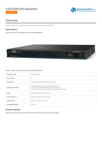
aggregated at the rack level in the network access layer. The access layer is in turn connected to the networkaggregation layer.Connectivity from EDA to HDA the ToR model will use fiber as the backbone cabling infrastructure that connects theEDA with the HAD and MDA. The ToR model augments the TIA/EIA-942 logical approach shown above in Fig. 1.1by extending fiber as the backbone cabling of choice to the EDA/server rack. The amount of fiber required will varybased on design requirements. For example, in a migration-type design where a ToR model is used for Ethernetaggregation and Fibre Channel (FC) connectivity is non-unified I/O (UIO), then additional fiber will be required forthose servers requiring FC connectivity. In models where UIO for FC and Ethernet is assumed, the fiber requirement tothe rack will be reduced. Other design augmentation, like a ToR for few racks with inter-rack cabling, will modify thefiber requirements. These are a few examples of some deployment models that have been adopted based on theparticular environment and requirements.The Pod ApproachThe easiest way to scale data center capacity is to use a highly modular architecture that enables the rapid deploymentof infrastructure. One approach is to use a rack of servers as the base building block with ToR switches, where allcopper cabling is contained within the rack.The TIA model provides a logical cabling layout that can be modularized for a data center build out. When deployinglarge volumes of servers inside the data center, it is extremely important that the design footprint be scalable. One wayto simplify the design and simultaneously incorporate a scalable layout is to divide the data center floor space intomodular, easily duplicated sub-areas.This modular building block is used to design scalability into the network architecture at both OSI Layers 1 and 2. It isassumed that all computer resources incorporate resilient network, power, and storage resources. This assumptiontranslates to multiple LAN, SAN, and power connections within the physical layer infrastructure. The logicalarchitecture is divided into three discrete layers (Core, Aggregation, Access), and the physical infrastructure is dividedinto manageable sub-areas called pods. From a network architecture perspective a pod is defined by a pair of Ethernetaggregation switches. Pods support access layer data link connectivity for low-latency inter-processor communications(IPC), Unified Fabric/Unified IO and Ethernet networks. A modular data center build coupled with a ToR access layerarchitecture provides facilities and network architecture scalability, flexibility and mobility to the rack level.-6-
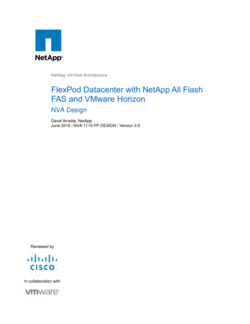
Physical Infrastructure and Network TopologyModular Cabling Architecture MethodologyCOLD AISLEDCPODRack ToRHOT AISLEZoneRack StoragePodRack ServerMixed RowsPODNetwork4 PODsRack Blade RackToR PODPODPODEoR Access PODEoR Blade PODFig. 1.2Figure 1.2 above shows a modular layout for a Greenfield data center. The pod-based modular concept incorporates thedifferent cabling architectures that may be required within the data center. More importantly it enables a modularbuilding block approach for server “rack and roll” deployment. In the reference shown, the data center floor plan isdivided into zones that are further subdivided into pods. A pod is used to represent a building block that defines thenumber of servers connected to a network aggregation block. Within the pod, server connectivity is handled at the racklevel by the ToR device, which is in turn connected to the network aggregation layer.Top of Rack Access Media ConsiderationsWhen considering 10-Gigabit Ethernet cabling infrastructure, the physics of the cabling plant must be considered.Factors such as signal attenuation, latency and distance, as well as cabling installation and termination best practices,are factors for careful consideration. Investing in the optimal cabling media for 10-, 40- and 100-Gigabit connectivityinvolves striking a balance between bandwidth, flexibility and scalability. Figure 1.3 below shows media andtransceiver options for 10G connectivity available today.-7-
10G Sever Connec vity Op ons–UTP/F-UTP, MMF, SMF, TwinAx, CX4Connector(Media)CableDistancePower(each side)TransceiverLatency (link)StandardSFP CU*Twinax 10m 1.5W .1 μsSFF 8431**Twinax15m4W 0.1 μsIEEE 802.3akMM OM2MM OM310m100m1W 0noneMM OM2MM OM382m300m1W 0IEEE 802.3aeCat6Cat6a/7Cat6a/755m100m30m 6W*** 6W*** 4W***2.5 μs2.5 μs1.5 μsIEEE 802.3ancopperX2 CX4copperSFP USRMMF, ultra short reachSFP SRMMF,short reachRJ45 10GBASE-Tcopper* Terminated cable** Dra 3.0, not final*** As of 2008; expected to decrease over meFig. 1.3There are several media and transceiver options available today for 10G server connectivity. Considerations for use casedepend on variables like cost, latency, distance, power consumption and technology availability. For 10G serverconnectivity today, SFP-based technology provides cost-effective and flexible options for server NIC and ToR switches.SFP cu (copper twinax) is currently the most optimal choice for server connectivity.For EDA to HDA horizontal connectivity, SFP USR/SR is better suited for longer distances between server (EDA)rack and network equipment racks located in the HDA. SFP USR provides cost-effective fiber connectivity for fiberbased server connectivity options. SFP copper may also interconnect a number of EDA racks to a central EDA / ToRdevice with horizontal backbone connectivity to the HDA or MDA.10GBaseT is, as of time of writing, power inefficient when compared to CX-1 and optical technologies. However, asmore power efficient 3rd- and 4th-generation silicon architectures coupled with IEEE 802.3az Energy Efficient Ethernetbecome available over the next few years, 10GBASE-T LOM (LAN on motherboard) and dense network switchingproducts will become technically and economically viable sever connectivity option.Fiber and Copper Cabling CharacteristicsFor data center builds there are a number of choices in optics and media. Consideration is required relative to the datacenter physical facilities requirements and media characteristics. The table below provides guidance on different opticsand usage in the data center.-8-
Max PMD Distance (m)1G Op cs Type1000 BASE-LX1000 BASE-SX1000 BASE-T10100500 10000Max PMD Distance (m)10G Op cs Type10GBASE-LR10GBASE-LRMRequire OM3 MMF10GBASE-SR10GBASE-T30M/100M10GBASE-USROM3 MMF Only10GBASE-CX410GBASE-CX11026-82100220300 10000In RackX-rackMid to Endof RackAcrossAislesAcrossSites 10M 100 M 300 M 10 KMFig. 1.4FiberWhen considering a data center build out, evaluation of near- and mid-term future is required to maximize theinvestment in cable plant. Because 10-, 40- and 100-Gigabit Ethernet will be standardized in the next 3-5 years, oneshould assess fiber optic cabling.Several grades of high-bandwidth laser-optimized fiber are available for use in high-speed network installations, eachwith a different reach and data rate: 62.5/125μm (OM1) fiber, designed to achieve 10 Mb/s and 100 Mb/s data rates, is now largely a legacy fiber 50/125μm (OM2) fiber, used to achieve 1 Gb/s data rates 50/125μm (OM2 , OM3, and OM3 ) fiber, used to achieve 10 Gb/s data rates; OM2 and OM3 fiber gradesoffer nearly double the bandwidth of their parent fibers (‘ ’ represents extended reach OM2 and OM3 fiber). SMF (ITU GR.652, TIA/EIA-493CAAA), standard single-mode fiber. Designed to support high capacity, low-cost transmission components developed for the 1310 nm window. SMF fibers feature low dispersion and isoptimized for use in the 1310 nm wavelength region. SMF fiber is also used effectively with WDM systemsoperating in the 15550 nm wavelength region. SMF fiber can be used for cross-isle and inter-data centerapplications. SMF fiber will support 40, 100G with serial implementations. (update this section)-9-
The most cost-effective fiber cabling is multi-mode fiber. It is found in nearly all data centers today and is capable ofsupporting 10-Gigabit Ethernet. However, as 40- and 100-Gigabit Ethernet become standardized, either multi-modefibers with parallel optics or single-mode fiber will be required. Single-mode fiber, although simpler to manage andmore amenable to higher bit-rate transmission, is more expensive to terminate and also more expensive in terms ofoptical transceivers that are required at the switch and host devices.CopperCopper cabling consideration for 10G server connectivity. Category 6A copper cabling was developed in conjunction with the 10GBASE-T standard to achieve reliable10 Gb/s operation over 100 m copper twisted-pair channels. Category 6A shielded and unshielded products aredesigned to extend usable bandwidth up to 500 MHz and to drastically reduce alien crosstalk interference. Inthe context of ToR architectures, Cat6a can be used within the rack.l (describe 6a copper more) 1X-based Twinax copper* is an alternative copper solution that uses SFP Direct Attach twinax cabling.Although this solution has a limited cable distance of up to 10 meters, it provides a robust, power efficient andcost-effective solution for 10-Gigabit Ethernet transmission. The SFP Direct Attach solution is a fully integrated SFP and cable that is available in multiple lengths up to10 meters. As the cabling distance is limited, each server is directly connected to a top-of-rack switch with nointermediate patch panels to manage. This dramatically simplifies cabling and termination as the cabling iscontained within a single rack and works well with the concept of a modular data center. The SFP directlyattached solution draws 0.1 Watts power per port, has a latency of 0.1 microseconds, and is available today.* Twin-ax cabling has been optimized for differential pair applications to support 10 Gb/s signaling. It employs aunique homogeneous construction with 100% shielding that enables completely new levels of data rates over a singleline with virtually no crosstalk. Both delay and amplitude skew are minimized because the one integral dielectriceliminates material variations and forces a nearly identical distance between conductors to be maintained. Twinaxcabling is limited today to 10 meters for passive implementation and 30 meters for active cabling solutions.Top-of-the-Rack Cabling RecommendationsThe ToR network architecture leverages available cabling media options with flexibility at the rack level to utilizedifferent sever patch cable types while taking advantage of fiber uplinks from the rack for horizontal cabling. AlthoughCX-1 twinax and fiber support high-speed 40- and 100-G transmission, fiber is the recommended horizontal cablingmedia as it provides an optimal solution for high-speed 40- and 100-G transmission over relatively long distances (up to300 meters). It should be noted that 40- and 100-G transmission requires multiple fiber strands (OM3/OM4/SMF fiber)plus optical interfaces that depend on the distance from EDA to HDA / aggregation.Limiting the use of copper to within racks, the ToR model isolates the cabling that changes most rapidly to the parts ofthe data center that change most frequently: the racks themselves. By using fiber runs from the racks, this architecturedelivers a flexible future-proof cable infrastructure that supports the transition from 1-Gigabit Ethernet to 10-GigabitEthernet today, and allows adoption of 40- and 100-Gbps Ethernet technologies in the future.InRack: Cabling within the rack is dependent on connectivity requirements that may be optimized around interface speed, latency, and cost of optics/transceiver. Copper options: SFP CX-1 Twinax, (UTP, F/UTP, S/FTP) or- 10 -
Fiber options: low-cost SFP USR or SX, SR, LM for short reach over multimode fiberOutside Rack: (Uplink to Aggregation) Fiber (OM3/OM4) if available; MM fiber recommended for lower cost on the fiber and the optics required fortermination. Fiber from rack (EDA) terminates at the aggregation (HDA)Fig. 1.5Figure 1.5 shows a facilities rack view of a raised-floor server rack and network rack. The fiber optic cabling is locatedover the server racks and terminates in fiber patch panels. Depending on requirements, the deployment may varyslightly in terms of the ToR device supporting a single rack or multiple racks.Top-of-the-Rack Model at Work with the Nexus 5000 and 2000The ToR architecture offers data center managers the ability to implement a single cabling model that can support 1and 10-Gigabit Ethernet and unified network fabric today, while supporting future 40- and 100-Gbps Ethernet standardsas they come to market. Using a single overhead cable tray for fiber optic cable management, data center managers havethe flexibility to deploy preconfigured racks with different connectivity requirements in any rack position. For example,a rack of servers running multiple Gigabit Ethernet connections might be placed next to a rack of servers with 10Gigabit Ethernet and Fibre Channel over Ethernet connections to each server. This section of the paper demonstrateshow Cisco Nexus products facilitate the top-of-rack switching and cabling model.Top of the Rack in Gigabit Ethernet EnvironmentsCisco offers a compelling ToR solution that is supported by Cisco Nexus products. Using the Cisco Nexus 2148-Tand Nexus 5000 switches at the access layer, data centers can build self-contained racks of servers with Gigabit Ethernet- 11 -
connectivity requirements using a small number of 10-Gigabit Ethernet fiber or CX-1 connections to an end-of-row ormiddle-of-row switch.The Cisco Nexus 2148-T (Fabric Extender) is an innovative server aggregation mechanism that extends Cisco Nexus5000 Series Switches into Gigabit Ethernet environments. Acting as a line card on a Cisco Nexus 5000 Series switch,the Cisco Nexus Fabric Extender aggregates up to forty-eight Gigabit Ethernet (fixed speed) connections at the rackand passes the network traffic up to the access-layer switch at the middle or end of the row. Because the Cisco NexusFabric Extender is an extension of the switch itself, it offers massive scale with no increase in management complexity.Physically, it distributes the access layer across data center racks. Logically, the access layer remains at the end of therow and is managed by the Cisco Nexus 5000 Series switch. The Cisco Nexus Fabric Extender provides up to fourSFP 10G uplinks supporting either 10G SFP optical transceivers or CX-1 direct-attach cable assemblies.Figure 1.6 below illustrates a row of dual-homed 1-Gig attached servers with two Nexus Fabric Extender devices ineach rack that are connected to Nexus 5010 or 5020 switches installed at the end of each row. Two Cisco Nexus FabricExtenders in each rack support forty servers per rack with no oversubscription if four 10-Gigabit Ethernet uplinks areconfigured.1-G attached servers are connected to the ToR Nexus Fabric Extender using Cat5e RJ-45 patch cables. Fibre uplinksprovide connectivity between Nexus Fabric Extender and upstream Nexus 5010/ 5020 switches. If all four FabricExtender uplinks are used to minimize oversubscription in the rack, then a total of 8 Fibre strands are utilized from eachrack to the end of the row.To Aggr2 x Nexus20002 x Nexus20002 x Nexus20002 x Nexus20002 x Nexus20002 x Nexus20002 x Nexus20002 x Nexus20002 x Nexus20002 x Nexus20001 x 50101 x 501010G SFP Fibre cables connecting FEX to Nexus 501010G SFP Fibre cables
TIA-942 Logical Layout EIA/TIA 568 Copper & Fiber Cabling ToR EoR Access / ToR Agg Core / EoR Agg Fig. 1.1 The equipment distribution area (EDA) in the TIA-942 logical layout would correspond to the area where server racks are placed. Traditional structured copper cabling w