Transcription
Design GuideCisco Data Center Services Node Architecture The Cisco Data Center Service Node (DSN) is a new product offering from Cisco that complements the Cisco Nexus 7000 Series Switches in the data center. Cisco DSN is the platform of choice to hostspecific integrated network services relevant in a given data center. Examples of network services includethe Cisco Firewall Services Module (FWSM) and the Cisco ACE Application Control Engine Module, forserver load balancing. The service node-based solution offers proven enterprise products enablingcustomers to use a common architecture and easily integrate the solution with existing networkinfrastructure. Deploying a consistent architecture using a common platform can reduce connectivity costssignificantly and increase network performance, manageability, and flexibility.Cisco DSN uses a dual-homed approach for data path connectivity to redundant aggregation-layer switches. Thisapproach decouples the service modules from dependence on a specific aggregation switch.Because the Cisco DSN is self-contained, it provides operational flexibility for the system maintenance that may berequired for the aggregation-layer switches or the Cisco DSN. From a high-availability perspective, if one of theaggregation switches or Cisco DSNs fails, traffic can continue to flow through the other aggregation switch to theactive Cisco DSN without the need of any failover event in the service modules themselves.IntroductionThis document provides reference design and configuration guidance about integrating the Cisco DSN into an enterprise data center. The Cisco DSN is a dedicated Cisco Catalyst 6500 Series services chassis housing threeCisco FWSMs and one Cisco ACE Module, providing up to 15 Gbps of secure load-balancing system throughput.The Cisco DSN enables cloud services by integrating firewall security and application delivery along with third-partysolutions and monitoring.AudienceThis document is intended for network engineers and architects who need to understand the design options andrequired configurations for the Cisco DSN (services chassis) architecture in a data center network.Data CenterThe data center is evolving into a cloud services environment. A cloud service is defined as providing infrastructure,platform, and software as a service. By moving toward a cloud computing environment, data centers can reducecosts, provide dynamic resources, improve flexibility, increase service-level agreements (SLAs), and increase space,bandwidth, and throughput. These benefits are especially important for the rapidly evolving area of data centernetworking. The need for higher-performing end nodes and along with the need for solutions that achieve more atless cost together are propelling data centers to migrate to 10 Gigabit Ethernet and implement server, network, andservices virtualization.As the network expands, a dedicated Cisco DSN is required to isolate all the services functions onto their own layer.A major advantage of the Cisco DSN is the capability to introduce new services in a controlled manner usingpredictable traffic patterns. The Cisco DSN consists of a Cisco Catalyst 6500 Series Switch using service modulesthat are dedicated to security and server load-balancing functions. The Cisco DSN can be directly attached to anaggregation-layer switch, such as a Cisco Nexus 7000 Series Switch, or it can use the Cisco DSN as theaggregation layer if ports are available. The primary goal of the Cisco DSN is to provide higher performance, 2010 Cisco and/or its affiliates. All rights reserved. This document is Cisco Public Information.Page 1 of 21
Design Guidereliability, and manageability by transparently applying network services in the data center to create a more flexible,functional, and secure server farm.In the first phase of Cisco DSN, two design scenarios are being evaluated. Design 1 (see Figure 1 later in thisdocument) focuses on a Layer 3 Cisco DSN with a routed Cisco FWSM and Cisco ACE along with virtual routeforwarding (VRF) instances defined on the Cisco Catalyst 6500 Series Multilayer Switch Feature Card (MSFC) of theCisco DSN. In design 2 (shown in Figure 3 later in this document), the Cisco DSN is on Layer 2, where no routingtakes places and both the Cisco ACE and Cisco FWSM are in transparent mode. The Cisco DSN applies theconcept of virtualization to the services-layer chassis. In each of the design cases, traffic that is segmented from thecore or aggregation layer is extended to the Cisco DSN. The VRF instance is mapped to an individual Cisco FWSMor Cisco ACE context, which is then mapped to the individual VLANs. By doing this in a cloud service data centerdeployment, customers can each have their own dedicated routing instances, a unique Cisco FWSM and Cisco ACEcontext, and a VLAN that extends to a particular service. Through virtualization, resources can be partitioned, givingeach context its own access control lists (ACLs), policies, interfaces, routing, etc, allowing customization andisolation for each customer. This flexibility enables the network administrator to achieve the best use of resourcesavailable from the Cisco DSN. The Cisco DSN allows traffic to be segmented throughout all layers of the network,providing an end-to-end cloud services model.The data center is an important part of the enterprise network. The data center network design must address highavailability for any device or link failure. Additional intelligence is required to provide services such as firewalling andload balancing of servers and the applications they host. This document examines architectural models forintegrating the Cisco DSN into the data center design.Components of the Cisco DSN BundleTable 1 lists the components of the Cisco DSN bundle.Table 1.Cisco DSN Bundle ComponentsPart NumberQuantity and ComponentsDSN09E-VS720-AC-K91 Cisco Catalyst 6509-E chassis 2 WS-CAC-6000W1 WS-S720-10G3 WS-SVC-FWM-1 (20 virtual context licenses per module)1 WS-ACE20-6500-K9 (16 GB performance and 20 virtual context license)1 WS-X6704-10GEDSN09E-VS720-DC-K91 Cisco Catalyst 6509-E chassis2 PWR-6000-DC1 WS-S720-10G3 WS-SVC-FWM-1 (20 virtual context licenses per module)1 WS-ACE20-6500-K9 (16 GB performance and 20 virtual context license)1 WS-X6704-10GEDSN06E-VS720-AC-K91 Cisco Catalyst 6506-E chassis2 WS-CAC-3000W1 WS-S720-10G3 WS-SVC-FWM-1 (20 virtual context licenses per module)1 WS-ACE20-6500-K9 (16 GB performance and 20 virtual context license)1 WS-X6704-10GEDSN06E-VS720-DC-K91 Cisco Catalyst 6506-E chassis2 PWR-4000-DC1 WS-S720-10G3 WS-SVC-FWM-1 (20 virtual context licenses per module)1 WS-ACE20-6500-K9 (16 GB performance and 20 virtual context license)1 WS-X6704-10GE 2010 Cisco and/or its affiliates. All rights reserved. This document is Cisco Public Information.Page 2 of 21
Design GuidePart NumberQuantity and ComponentsDSN9VE-VS720-AC-K91 Cisco Catalyst 6509-V-E chassis2 WS-CAC-6000W1 WS-S720-10G3 WS-SVC-FWM-1 (20 virtual context licenses per module)1 WS-ACE20-6500-K9 (16 GB performance and 20 virtual context license)1 WS-X6704-10GEDSN9VE-VS720-DC-K91 Cisco Catalyst 6509-E chassis2 PWR-6000DC1 WS-S720-10G3 WS-SVC-FWM-1 (virtual context virtual context license)1 WS-ACE20-6500-K9 (16 GB performance and 20 virtual context license)1 WS-X6704-10GENote:The Cisco FWSM and Cisco ACE are not limited to the support of the chassis, power supplies, and linecards listed here. The list of hardware is specific to the Cisco DSN bundle that can be ordered.VirtualizationYou can use varying degrees of virtualization in the network to help increase resources, bandwidth, andperformance, and you can use various technologies and features to help accelerate virtualization in the data center.The Cisco DSN design cases use virtual device contexts (VDC), virtual PortChannel (vPC), virtual switching system(VSS), VRF, and Cisco FWSM and Cisco ACE virtualization.VDC allows engineers to logically partition or virtualize the Cisco Nexus 7000 Series connections to multiple logicaldevices. A VDC contains its own unique and independent set of VLANs and VRF instances. Each VDC can have aseparate port assigned, allowing the hardware date plane to be virtualized as well. Within each VDC, a separatemanagement domain can manage each VDC, allowing the management plane to be virtualized as well. VDCs areused to improve ease of configuration, supportability, and security. vPC is a feature on the Cisco Nexus 7000 Seriesthat allows an EtherChannel to be formed across two physical devices.VSS combines two physical Cisco Catalyst 6500 Series Switches into one virtualized switch. This arrangementenables a unified control plane and also allows both data planes to forward simultaneously. With VSS, multichassisEtherChannel (MEC) is introduced, which allows a PortChannel to be formed across two physical switches. vPC andVSS both provide enhanced system availability through redundant systems, eliminate reliance on Spanning TreeProtocol, achieve faster convergence times, and enable full system availability at all time. For the Cisco DSN usecases, the aggregation-layer switches can run in vPC mode and interconnect to the Cisco DSN through MEC, whichwill be running in the VSS. An additional benefit of integrating VSS with Cisco DSN is that this integration increasesthe number of supported service modules per chassis from four to eight in a single VSS domain, enabling an activeactive highly available service chassis.VRF instances allow multiple routing configurations in a single Layer 3 switch, with separate virtual routing tables.VRF-lite segregates customer traffic at Layer 3 to optimize use of data center resources. VRF-lite end-to-endtechniques are used to provide customer path isolation. VRF offers these advantages: True routing and forwarding segmentation Simplified path differentiation (different default routes can be used for each VRF instance) Support on both Cisco Catalyst 6500 Series and Cisco Nexus 7000 Series platformsEach customer is assigned a VRF identity. VRF information is carried across all the hops in a Layer 3 domain, andthese VRF’s will then be mapped to one or more VLANs in a Layer 2 domain. Communication between VRFinstances is not allowed by default to protect the privacy of each customer. 2010 Cisco and/or its affiliates. All rights reserved. This document is Cisco Public Information.Page 3 of 21
Design GuideVirtualization on Cisco FWSMA single Cisco FWSM can be divided into multiple virtual devices, with each virtual device known as a securitycontext. Each context has its own security policy, interfaces, and administrators. Having multiple contexts is similarto having multiple standalone devices and is a great way to reduce costs while keeping all customer traffic separateand secure. Many features are supported in multiple-context mode, including routing tables, firewall features, andmanagement. The Cisco FWSM supports up to 250 virtual contexts.The Cisco FWSM provides the following features: Route health injection (RHI) Virtualization (context and resource allocation) Application inspection Redundancy (active-active context failover) Security and inspection Network Address Translation (NAT) and Port Address Translation (PAT) URL filtering Layer 2 and 3 firewalling Protocol inspectionVirtualization on Cisco ACEThe virtualized environment is divided into objects called contexts. Each context behaves like an independent CiscoACE with its own policies, interfaces, domain, server farms, real servers, and administration. You can use it toprovision resources per context with most feature subsystems virtualized.The Cisco ACE Module provides the following features: RHI Virtualization (context and resource allocation) Probes and server farm (service health checks and load-balancing predictor) Stickiness (source IP and cookie insert) Load balancing (protocols, stickiness, FTP inspection, and SSL termination) NAT (static and dynamic NAT for management and software updates) Redundancy (active-active context failover)The Cisco FWSM and Cisco ACE both have distinct feature sets in security and application load balancing.However, several security features overlap between the two, as shown in Table 2.Table 2.Security Features: Comparison of Cisco FWSM and Cisco ACEFeatureCisco FWSMCisco ACEBidirectional NAT, static and dynamic NAT and PAT, and policy-based NATYesYesVRF-aware NATYesNoDestination NAT for multicastYesNoStatic routing (Layer 2 only)YesYes 2010 Cisco and/or its affiliates. All rights reserved. This document is Cisco Public Information.Page 4 of 21
Design GuideFeatureCisco FWSMCisco ACEDynamic routing (Open Shortest Path First [OSPF], Routing Information Protocol [RIP]Versions 1 and 2, Protocol-Independent Multicast [PIM], Internet Group Management Protocol[IGMP] Version 2, and Internet Border Gateway Protocol [iBGP] in single and multiple context)YesNoURL filtering (HTTP, HTTPS, and FTP)YesYesDOSYesYesDomain Name System (DNS) guardYesNoFlood guard and defenderYesNoTCP intercept with SYN cookieYesYesUnicast Reverse Path Forwarding (URPF)YesYesMail guardYesNoVirtual reassemblyYesYesICMP stateful inspectionYesYesUDP rate controlYesYesTCP stream reassemblyYesYesTCP traffic normalization services for attack detectionYesYesNAT translation bypassYesNoSelective TCP state bypass per flowYesNoBidirectional ACL, extended ACL for IP traffic, and EtherType ACL for non-IP trafficYesYesPer-user ACL and override and time-based ACLYesNoAddress Resolution Protocol (ARP) inspection in Layer 2 modeYesYesDynamic Host Configuration Protocol (DHCP) server and relayYesNoSimple Network Management Protocol (SNMP) and syslogYesYesProtocol inspectionYesYesActive-Active Mode with Multiple Virtual ContextsWith VSS, the service modules will be in active-active mode, with each virtual context in active-standby mode on thedesignated service modules of each Cisco DSN.This model uses the virtualization capabilities of the Cisco FWSM and Cisco ACE Module to distribute a portion ofthe traffic across both services chassis. The traffic is not automatically balanced equally across the devices;however, the network administrator can assign different server farm subnets to specific contexts, based on expectedload or on other factors. Routing virtualization is also used in the active-active model through the implementation ofVRF instances in the aggregation switches. In the active-active routed Cisco DSN model (see Figure 1 later in thisdocument), all Layer 3 processing takes place on the Cisco DSN, making both the Cisco FWSM and Cisco ACE inrouted mode. In Design 2, the transparent Cisco DSN model acts as a pure Layer 2-connected switch.The active-active design model allows the Cisco FWSM and Cisco ACE in the Cisco DSN to support an activecontext, optimizing resources in each Cisco DSN through load distribution across the Cisco DSN pair (VSS). Toachieve an active-active design, failover groups are defined for each service module. Failover groups contain virtualcontexts and determine which physical Cisco FWSM and Cisco ACE will be active for the particular group. Eachmodule is assigned a primary and secondary priority status for the failover group. The fault-tolerant interfacebetween the Cisco FWSM and Cisco ACE on each chassis uses a separate physical connection between chassis.Since the Cisco DSN is a VSS configuration, all configured VLANs are carried across the virtual switch links (VSLs).As a result, no separate links are needed for fault-tolerant links or stateful connectivity.With the virtualization capabilities of the Cisco Catalyst 6500 Series services modules, separate contexts can becreated that behave like separate virtual devices. The first Cisco FWSM and Cisco ACE are primary for the firstcontext and standby for the second context. The second Cisco FWSM and Cisco ACE are primary for the second 2010 Cisco and/or its affiliates. All rights reserved. This document is Cisco Public Information.Page 5 of 21
Design Guidecontext and secondary for the first context. This setup allows modules on both sides of the designs to be primary fora portion of the traffic, and it allows the network administrator to optimize network resources by distributing the loadacross the topology instead of having one set of modules nearly idle in a pure-standby role.Note:In an active-active design, network administrators must properly plan for failure events in which one servicemodule supports all the active contexts. If the total traffic exceeds the capacity of the remaining service module, thepotential to lose connections exists; thus, it is important to size the VSL accordingly. It is a best practice for thebandwidth of the VSL to be equal to the total amount of uplink traffic coming into a single chassis.For more information, please refer to these links: s tech note09186a0080a7c72b.shtml http://www.cisco.com/go/vss/Design ConsiderationsFor Cisco DSN, two design options are considered here. In option 1, routed Cisco DSN (shown in Figure 1 later inthis document), the Cisco FWSM and Cisco ACE both are in routed mode. In addition, VRF is defined on the CiscoDSN MSFC. The routed Cisco DSN use case has been validated by Enterprise Solutions Engineering. For moredetailed information about this use case, please refer docid 5656.In option 2 (see Figure 3 later in this document), called transparent Cisco DSN, no routing occurs on the Cisco DSN,and the Cisco FWSM and Cisco ACE are set to transparent mode. The option 2 design guide and validation areexpected to be available the third quarter of 2010 (Q3CY2010).For both design options, there are two use cases: one with Cisco FWSM facing the servers, and one with Cisco ACEfacing the servers. Depending on the design requirements, Cisco FWSM or Cisco ACE can face the servers. In therouted Cisco DSN validated design, Cisco FWSM faces the servers.Having Cisco FWSM face the inside server farm and Cisco ACE face the Internet offers several benefits: In a large managed data center deployment, the service provider can provide an initial firewall outside thedata center network. The firewall inside the data center network protects inter-data center traffic (that is, traffic from critical serversto noncritical servers and the opposite). The Cisco FWSM is positioned as the default gateway for the servers in the server farm. If Cisco FWSM isused as the default gateway for a server subnet, any server-to-server traffic between subnets is firewalled aswell. For example, n-tier applications using application-to-database server connectivity can be secured. At the data center entry point, Cisco ACE can handle the Layer 4 to 7 security (inspection) along with basicNAT and PAT. The ACL provides load balancing across the various application servers. Cisco ACE can serve as a load balancer across multiple firewalls to provide higher firewall throughput.Having Cisco ACE facing the inside server farm and Cisco FWSM facing the Internet offers these benefits: This approach can be applicable in a private data center owned and operated by a large enterprise. Cisco ACE server load balancing serves as a pure load balancer across application servers. Cisco FWSM provides a first layer of defense across Layer 2 to 7, NAT and PAT, and application inspection. Cisco FWSM can segregate traffic at the data center edge into inside, outside, and DMZ traffic with differentpolicies. 2010 Cisco and/or its affiliates. All rights reserved. This document is Cisco Public Information.Page 6 of 21
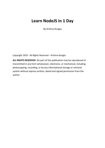
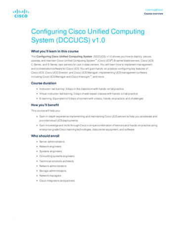
Design GuideDesign Option 1: Routed Cisco DSNDesign option 1 (Figure 1) uses routed Cisco DSN. With routed Cisco DSN, both the Cisco FWSM and Cisco ACEare in routed mode, thus forming one of the two default gateway for the servers. A routed service device isconceptually easier to implement and troubleshoot than a transparent service device, since there is a one-to-onecorrelation between VLANs and subnets and a simplified spanning-tree structure because the device is notforwarding Bridge Protocol data units (BPDUs) between VLANs.Figure 1.Routed Cisco DSN: Physical TopologyThe Cisco ACE can be configured with SSL offload for virtual machines. It uses multiple VLANs to segment virtualmachines into different networks hosting multi-tiered applications. The Cisco ACE is configured to run with multiplecontexts in routed mode. For server load-balancing (SLB) traffic, each context is configured with client- and serverfacing VLANs. The server-facing VLAN is shared with the outside VLAN on the Cisco FWSM. The Cisco ACE usesstatic routes with the Cisco FWSM as the gateway to reach the virtual machines.The Cisco FWSM is configured to run in multiple-context routed mode, acting as the default gateway for the virtualmachines. In routed mode, the Cisco FWSM acts as a router between connected networks, and each interfacerequires an IP address on a different subnet. The firewall context provides security between virtual machine VLANs,which are associated with a single customer, and routes traffic between the VLANs and outbound network asrequired. Each firewall is configured with VLANs local to the virtual machines and uses a static default route to routetraffic to clients, pointing to the Cisco ACE’s server-side VLAN’s alias IP address. Multiple-context mode supports 2010 Cisco and/or its affiliates. All rights reserved. This document is Cisco Public Information.Page 7 of 21
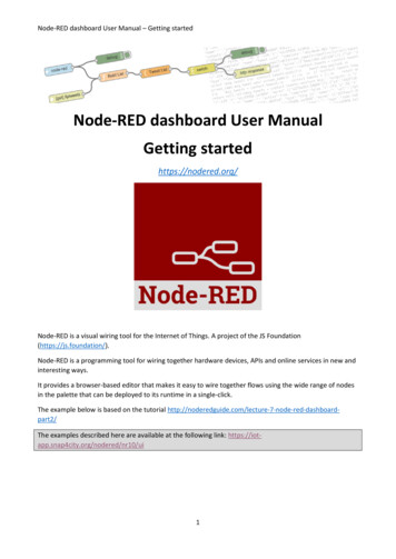
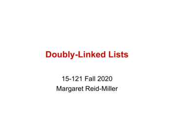
Design Guidestatic routes only, so the Cisco FWSM is configured to use a static default route to the Cisco ACE for client oroutbound access. The Cisco FWSM does not support dynamic routing in multiple-context mode.Figure 2 shows the logical topology.Figure 2.Routed Cisco DSN: Logical TopologyTraffic flows from the client to the server and from the server to the client as follows:1.Traffic from clients to the virtual IP is routed to the edge router.2.The edge router routes traffic to the appropriate VRF instance (VRF Red) on the Cisco DSN.3.The Cisco DSN routes this traffic to the outside Cisco ACE context’s client-facing VLAN 200.4.The Cisco ACE context performs server load balancing.5.The Cisco ACE context rewrites the destination address to the address of the virtual machine.6.The Cisco ACE uses static routes to forward the traffic from the server-side VLAN to the shared (outside) CiscoFWSM, VLAN 100.7.The Cisco FWSM forwards traffic directly to the servers, using a separate VLAN for each application type.8.Return traffic from the virtual machines is routed back to the Cisco FWSM (default gateway), VLAN 20.9.The Cisco FWSM uses the default route and forwards traffic to the Cisco ACE’s server-facing VLAN through theshared (outside) Cisco FWSM, VLAN 100.10. The Cisco ACE context has a default route for the client traffic pointing to a Layer 3 switch virtual interface (SVI)(VRF Red) on the services switch, accessible through the client, VLAN 200. 2010 Cisco and/or its affiliates. All rights reserved. This document is Cisco Public Information.Page 8 of 21
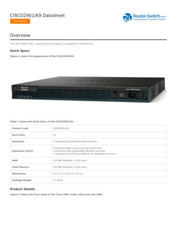
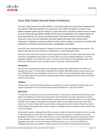
Design Guide11. The Cisco ACE contexts rewrites the source address as the virtual IP address and routes traffic to the CiscoDSN (MSFC).12. Using dynamic routing, the VRF on the Cisco DSN (MSFC) forwards the traffic to the edge router through Layer2 to the aggregation switch.13. The edge router routes traffic to the Internet backbone or VPN.Note:The routed Cisco DSN design use case has been validated by the services and systems business team).For more information, see cid 5656.Design Option 2: Transparent Cisco DSNIn transparent mode (Figure 3), the service modules bridge traffic from the VLANs that are chained together. Thetraffic is forwarded across a distinct set of VLANs within a subnet, acting as a “bump in the wire.”Figure 3.Transparent Cisco DSN: Physical TopologyA transparent firewall requires less configuration than a routed firewall, since there is no routing protocol to configureor list of static routes to maintain. It requires only a single IP subnet on the bridge-group interface, and it forwardsBPDUs between bridging devices that reside on attached segments; in that way, it is truly transparent and not abridge itself. The VLANs on the different interfaces of the transparent Cisco FWSM have different VLAN numbers, soa transparent device is often said to chain VLANs together. 2010 Cisco and/or its affiliates. All rights reserved. This document is Cisco Public Information.Page 9 of 21
Design GuideNote:The Cisco FWSM supports a maximum of eight bridge-group virtual interfaces (BVIs) per context.In the transparent Cisco DSN model, the Cisco FWSM is configured for multiple-context transparent mode in anactive-active Cisco DSN. Having the Cisco FWSM in transparent mode helps ensure that the firewall context is in thepath of traffic and is capable of applying the security polices defined for it.Cisco ACE is used as multiple-context in bridged mode. The transparent Cisco ACE implementation works similarlyto the Cisco FWSM implementation, in which multiple VLANs are chained together to transport one IP subnet, andBPDUs are forwarded to allow adjacent switches to perform spanning-tree calculations. A transparent Cisco ACEsits in line with traffic and requires no traffic-diversion mechanism to help ensure that both sides of a protocolexchange pass through the device. The Cisco ACE supports a maximum of two Layer 2 interface VLANs per bridgegroup and a maximum of 2000 BVIs per system. The BVI is configured to provide VLAN bridging.The VDC capability of the Cisco Nexus 7000 Series enables the network architect to use VDC. A secondary virtualswitching layer called the subaggregation layer can be created using VDCs, located between the Cisco DSN and theaccess switches. The insertion of a separate set of VDCs into the design still represents the use of a single physicalpair of switches to perform these functions but provides better isolation between the routing environments above andbelow the Cisco DSN. The Cisco DSN must have separate physical connections to both sets of VDCs rather thanhaving VLANs sharing the same trunks. Additional interfaces must also be provisioned to support the Inter-SwitchLink (ISL) between the two subaggregation-layer VDCs.Figure 4 shows the logical topology.Figure 4.Transparent Cisco DSN: Logical Topology 2010 Cisco and/or its affiliates. All rights reserved. This document is Cisco Public Information.Page 10 of 21
Design GuideTraffic flows as follows:1.The customer is identified by VRF Red, defined on the edge router.2.VRF Red traffic from clients to the server virtual IP address is routed to the aggregation switch.3.VRF Red traffic is associated with VLAN 300 and is transported across an IEEE 802.1q trunk through Layer 2(VLAN 300) to the Cisco DSN active Cisco FWSM context.4.The Cisco FWSM context performs a security check and bridges the traffic from the server-side VLAN to theshared (outside) Cisco ACE, VLAN 200.5.6.The Cisco ACE context performs server load balancing.The Cisco ACE context bridges the traffic to VLAN 100 and rewrites the destination address as the address ofthe virtual server. Traffic is forwarded across the Layer 2 trunk to the subaggregation-layer switch.7.The subaggregation-layer switch forwards traffic from VLAN 100 from the inside Cisco ACE VLAN to the server(VLAN 21) and associates it with VRF Red.8.9.The subaggregation-layer switch routes the traffic to the appropriate server.Return traffic from the virtual machines is routed back to the subaggregation-layer switch through VRF Red(VLAN 21), which is the default gateway.10. The subaggregation-layer switch forwards the traffic to the inside Cisco ACE, VLAN 100.11. The Cisco ACE context rewrites the source address as the virtual IP address and bridges the traffic to the CiscoFWSM.12. The Cisco ACE forwards the traffic to the server-facing VLAN through the shared (outside) Cisco FWSM,VLAN 200.13. The Cisco FWSM context has a default route for the client traffic pointing to the Cisco DSN MSFC throughVLAN 300.14. The Cisco DSN forwards the traffic through Layer 2 (VLAN 300) to the aggregation switch, which routes thetraffic to the Internet backbone or VPN through VRF Red.Note:The transparent Cisco DSN model is currently in the validation process by the services and systemsbusiness team. The design guide is expected in Q3CY2010.In both the routed and transparent options, the Cisco DSN is in an active-active configuration. In an active-activeconfiguration, a particular context can be in active mode on one service module and in standby mode on the other;per context basis Cisco ACE and Cisco FWSM provides traffic load-balancing. As shown in the topology, the Redcontext is active on the left Cisco ACE, and the Green context is active on the right Cisco ACE. Both contexts are instandby mode on the respective peer Cisco ACE modules, and additional VLANs are carried over the ISL to providefault tolerance and state synchronization. If one of the Cisco ACEs incurs a failure, the standby context on the peerCisco ACE will become active right away with little traffic distruption. Active-active design enables traffic load sharingand redundancy. As shown in Figure 4, client-to-server traffic for some contexts will use the links on the left, and therest will use the links on the right.In both Figures 3 and 4, the fault-tolerant link for the Cisco FWSM context between the Cisco DSN nodes consists ofVLANs 171 and 172. The Cisco ACE context has a dedicated fault-tolerant interface, VLAN 160. This VLAN providesconfiguration synchronization, state replication, and unit monitoring functions. Fault-tolerant groups enable greateravailability and load distribution in the data center by allowing the distribution of active virtual contexts between twopeering Cisco ACE Modules. In an active-active design, at least two fault-tolerant groups
Cisco Data Center Services Node Architecture The Cisco Data Center Service Node (DSN) is a new product offering from Cisco that complements the Cisco Nexus 7000 Series Switches in the data center. Cisco DSN is the platform of choice to host specific integrated network services relevant