Transcription
University of Arkansas, FayettevilleScholarWorks@UARKMechanical Engineering Undergraduate HonorsThesesMechanical Engineering5-2007A study on the application of thermoelectric heatpumps for heating applicationsJames LincicomeUniversity of Arkansas, FayettevilleFollow this and additional works at: http://scholarworks.uark.edu/meeguhtRecommended CitationLincicome, James, "A study on the application of thermoelectric heat pumps for heating applications" (2007). Mechanical EngineeringUndergraduate Honors Theses. 11.http://scholarworks.uark.edu/meeguht/11This Thesis is brought to you for free and open access by the Mechanical Engineering at ScholarWorks@UARK. It has been accepted for inclusion inMechanical Engineering Undergraduate Honors Theses by an authorized administrator of ScholarWorks@UARK. For more information, pleasecontact scholar@uark.edu.
A Study on the Application of Thermoelectric Heat Pumpsfor Heating ApplicationsAn Honors Thesis submitted in partial fulfillmentof the requirement for the Honors Program for theDegree of Bachelor of ScienceInMechanical EngineeringByJames Paul Lincicome, Mechanical EngineeringProject Advisor - Dr. Rick J. CouvillionMay 2007University of Arkansas
Table of ContentsAbstract1Introduction1Background2Technical Information3Performance Calculations6Experiment Design8Data and Results9Conclusions13Recommendations14Works Cited16Appendix A: Excel experiment data17Appendix B: Manufacturer’s data21ii
List of TablesTable 1: Overall performance of configurations13iii
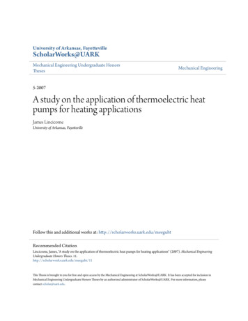
List of FiguresFigure 1: Diagram of Thermoelectric Module4Figure 2: Picture of Experiment Configuration8Figure 3: Temperature vs. Time all configurations10Figure 4: No fan, stage COP comparison11Figure 5: Fan, stage COP comparison11Figure 6: Single-stage fan COP comparison12Figure 7: Two-stage fan COP comparison12iv
AbstractTypically, thermoelectric heat pumps are used in cooling applications where spaceand portability are important, but they can be used efficiently in heating applications underthe right conditions. This paper explains the origins of the thermoelectric heat pump, itsapplications in society, and the technical aspects of the device. The many differentappurtenances that the device requires will be discussed along with their drawbacks. Thesingle-stage data for the cells will be compared to the two-stage configuration data, and thedata gathered for a specific thermoelectric device will be compared to the manufacturer’spublished data for the different configurations of the device.IntroductionWhile the technology used in thermoelectric heat pumps, also called thermoelectriccells or Peltier cells (TECs), has been around for many years, widespread commercializationdid not occur until the early 1960’s. At that time, the inefficiencies of thermoelectric heatpumps and their high price tag made them less desirable for use in cooling applicationscompared to conventional heat pump systems. Recently, the realization of the depletingozone layer has left scientists and engineers looking for alternatives to the conventional heatpump and the harmful refrigerants that they utilize. These refrigerants containchlorofluorocarbons that damage the ozone layer irrevocably. A potential alternative, alongwith environmentally-friendly refrigerants, was thermoelectric heat pumps. Over time,research showed that in small wattage cooling applications, the inefficiencies experienced bythermoelectric heat pumps was not enough to outweigh their advantages. In applications lessthan a couple of hundred watts, thermoelectric heat pumps were found to be very portablebecause of their small size, extremely reliable, and quite durable over a large range ofcooling temperatures. Because there are no moving parts in a TEC, there is no concern overwear or fatigue, and they are resistant to extremely high shock levels (Buist, 1-2).As these advantages were being realized, the price to manufacture these TEC’s beganto decrease making the thermoelectric heat pump a very good alternative to the typicalrefrigeration system. Many different uses for the devices began to be explored with some1
experiencing considerable success compared to others. For example, TECs were applied inroom air conditioners, dehumidifiers, and full-size refrigerators with poor results (Egli, 3437), but they began to be widely used in consumer applications such as the portable 12-voltcooler and small portable refrigeration devices that were easily plugged into wall outlets orcar cigarette lighters (Buist, 3). They have also played a large part in computer cooling, andas computers continue to become more powerful and heat-producing, cooling will becomeeven more important (Rowe, 143). Within the last ten years, TECs have been used in luxuryvehicles as seat heaters and coolers; since a simple reversal of polarity will shift the hot andcold side of the device, they are extremely well suited to this application.Currently, thermoelectric heat pumps are manufactured primarily for their coolingcapabilities, but they are also very efficient in heating applications. This paper will firstexplore the specific properties of the thermoelectric heat pump and its origins and thenresearch the potential for using the cells in heating applications. Data taken from a CustomThermoelectric, Inc. device used in heating will be compared to the manufacturer’s publisheddata and conclusions will be drawn from the comparison.BackgroundIn 1821, a German-Estonian physicist, Thomas J. Seebeck, accidentally, discoveredthat there was a voltage between the two ends of a metal bar when a temperature differenceexisted in the bar (Wikipedia, 1). In 1923, he proposed that a circuit composed of twodissimilar conductive metals with two different temperatures creates an electromotive force(emf) at the junction between the two metals. This is called the “Seebeck Effect,” and it wasdetermined that the emf at each junction was proportional to the temperature differencebetween the junctions according to:E AB S AB Twhere:SAB is the relative Seebeck coefficient between the materials,EAB is the emf between the two junctions, and T is the temperature difference between the two metals.The relative Seebeck coefficient between materials A and B, SAB, is defined as:S AB S A S B2
where:SA and SB are the Seebeck coefficients of the two materials.Eleven years later, Jean C. A. Peltier discovered the exact opposite of the SeebeckEffect; when a circuit composed of two dissimilar conductive metals carries an electriccurrent, heat is produced at one junction and absorbed at the other. This process, the “PeltierEffect,” is fully reversible and is the process by which thermoelectric cells work. The rate atwhich heat is produced is dependent on the properties of the metals, as in the Seebeck Effect,and the current flowing through the circuit according to the following equation:Q AB Π AB Iwhere:QAB is the rate at which heat is produced on the hot side and absorbed on the coldside,ΠAB is the relative Peltier coefficient, andI is the current flowing through the circuit.The relative Peltier coefficient is given by:Π AB Π A Π Bwhere ΠA and ΠB are the Peltier coefficients of the two metals (Cadoff, 2-5).The Peltier coefficients represent how much heat current per unit charge is carried through agiven material.Technical InformationThermoelectric heat pumps, or TECs, are solid-state devices that function as heatpumps. They are typically only a few millimeters thick and only a few centimeters square.The normal TEC will be made up of an array of p- and n-type semiconductor elements thatare dissimilar because they can be easily optimized for pumping heat and can control the typeof charge carrier. The semiconductors typically used in TECs are composed of bismuthtelluride, although many different types of materials have been used in the past. The array issoldered between two ceramic plates, electrically in series and thermally in parallel. Whensmooth direct current (DC) passes through the p-type to the n-type semiconductor, atemperature drop is experienced at the junction according to the Peltier Effect. Thisproduction of a cold side makes the cell absorb heat from the environment. This heat is then3
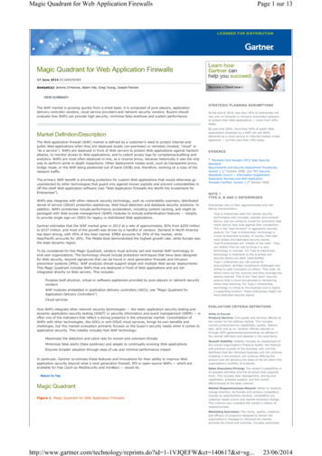
passed through the cell by electron transportand released on the opposite hot side. Theheating capacity of the cell increases as theamount of p-type and n-type pairs increases(Marlow, 1-2). A diagram of a normalthermoelectric heat pump is shown to the right.TECs require smooth DC current somany different sources of power can be usedFigure 1: Diagram of thermoelectric modulesuch as batteries, automotive and marine DC systems, AC/DC converters, and linear andswitched DC power supplies. The rating on a TEC is the maximum current or voltageallowable to the cell. For example, the cells that were purchased for research for this studywere six ampere, 12-volt devices, and above these parameters, the cell would not functionproperly and likely be destroyed. The cells operate most efficiently at 75% of maximumpower. As stated earlier, the Peltier Effect is reversible, so if the power input reversedpolarities, the cell’s hot side would become the cold side and vice versa (gatewayelex, 1).One concern in using a TEC is the dispersion or gathering of heat. In typical coolingapplications, it is necessary to have a heat sink to disperse heat to the environment on the hotside, and likewise, in heating applications, a heat sink must be used on the cold side to gatherheat from the environment. Heat transfer between two surfaces depends on the temperaturedifference between the surface and the contact area of the surfaces (JC Electronica, 2). Oneimportant note is that to effectively have heat transfer from the surface of the cell to the heatsink, the surface area must be maximized to maximize heat transfer. There are microscopicpeaks and valley in the surface of the heat sink and the ceramic face of the TEC that reducethe surface area available for heat transfer. To overcome this, thermal interface material(TIM) must be applied between the interface of the heat sink and the TEC surface and alsoapplied between the object to be heated or cooled and the TEC surface. This TIM willmaximize the available surface area of the cell and heat sink to allow for maximum heattransfer. The TIM can be made from any number of materials such as silicone-based greases,elastomeric pads, thermally conductive tapes, or thermally conductive adhesives. Any ofthese will suffice; however, if a grease is used, because the peaks and valleys are4
microscopic, only a very thin film of heat sink grease should be used or the grease will act asanother thermal resistance rather than an aid to heat transfer (peltier-info.com, 4).The most important factor in the function of a TEC is the dissipation of heat on thehot and cold side, or the heat sink. The efficiency of the heat sink is the most important factorin the achievable temperature difference across the thermoelectric heat pump(gatewyelex.com, 1). The TEC can be mounted to the heat sink in a few ways such as epoxy,soldering, or compression, but some TIM must be included between the interfaces. In mostapplications, the TEC is used to heat or cool a solid body or the contents of a container, andsome consideration must given to how best transfer heat to or from the body. The materialthat interfaces between the body to be cooled or heated and the TEC must be highlyconductive.Recently, most research involving the optimization of TECs has been exploringmultiple heat sinking options. The heat sink can be made of any highly conductive materialsuch as aluminum or copper and even a heat sink extender (HSE) can be used in applicablecases. An HSE can be used to extend the distance between the cold sink plate and the hotsink plate to minimize the heat transfer between the two plates. The area around the HSEshould be well insulated, and the HSE must also be a highly conductive material (AIP, 161).The heat sink should be finned and also be air cooled or liquid cooled, and in each case, thefluid should be moving across the highly conductive heat sink to reduce the heat transfercoefficient. Because liquid has a higher coefficient of heat transfer, to maximize theperformance of the TEC, a liquid should be moved across the heat sink. While this is themore efficient option, it is much more difficult to use in practice (AIP, 147). When using aliquid with a TEC, there is a concern for moisture reaching the cell. To prevent this, theremust be a seal around the TEC area to guard against condensation or any lost liquid in thearea (gatewayelex.com, 3). The alternative to using a liquid is moving air across the finnedheat sink, and this is the focus of this research.Research has been conducted to determine the optimal configuration of an air-cooledheat sink coupled with thermoelectric heat pumps. In heating applications, the heat sink onthe cold side must perform well enough that the cold heat sink continues to draw heat fromthe atmosphere. To maximize the heat transfer coefficient of the air, a fan or blower must beused. Investigations have shown that the better option if the heat sink has very few fins (i.e.,5
fourteen fins over a length of five inches), is a blower (AIP, 147-149). If the heat sink has ahigher fin density, a fan is a better option because a blower must overcome a more significantpressure drop to move air from the finned area. As the volumetric flow rate of air increases,the overall heat sink resistance (HSR) decreases, and likewise at a similar volumetric flowrate of air, as the number of fins increases, the HSR also decreases to a certain point.Therefore, to optimize the heat sink for a specific thermoelectric application, the optimalnumber of fins should be determined by calculation or experimentation (AIP, 147-149).Performance CalculationsIn cooling applications, thermoelectric heat pumps are approximately 75% efficient,but if u
room air conditioners, dehumidifiers, and full-size refrigerators with poor results (Egli, 34- 37), but they began to be widely used in consumer applications such as