Transcription
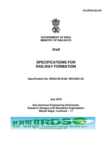
For official use onlyGOVERNMENT OF INDIAMINISTRY OF RAILWAYSDraftSPECIFICATIONS FORRAILWAY FORMATIONSpecification No. RDSO/2018/GE: IRS-0004 (D)July 2018Geo-technical Engineering Directorate,Research Designs and Standards OrganisationManak Nagar, Lucknow – 11
Specifications For Railway bleTerminologyFormation ComponentsSoil ClassificationMaterials for Formation and Soil encountered in CuttingSuitability of subsoilExecution of EarthworkBlanket LayerThickness and specifications of Formation LayersQuality control of EarthworkSlope stability criteria and conditionsErosion control measure methods on Embankment and slopesMaintenance of recordsMiscillaneous PointsBibliography & ReferencesAPPENDIX-A: Soil Exploration & SurveyAPPENDIX-B: Slope Stability Analysis MethodAPPENDIX-C: Execution of Formation EarthworkAPPENDIX-D: Applications of Geosynthetics in Track FormationAPPENDIX-E: Widening of Embankment, Raising of Existing Formation & cess repairAPPENDIX-F: Rehabilitation of Existing Unstable FormationAPPENDIX-G: List of Equipment’s for Field LabAPPENDIX-H: Various SketchesAPPENXIX-J: Details of Borrow Soil/Formation Subgrade/Prepared SubgradeAPPENDIX-K: Field compaction trial observations & computation sheetsAPPENDIX-L: Salient Features of Vibratory Rollers Manufactured in IndiaAPPENDIX-M: Typical compaction characteristics of Natural soil, rocks & artificialmaterialsAPPENDIX-N: Ground Improvements Techniques/Soft Ground Improvement MethodsAPPENDIX-P: Quality Assurance TestsAPPENDIX-Q: Modern Equipments for Earth WorkAPPENDIX-R: Transition System on Approaches of BridgesAPPENDIX-S: Fitment of Existing Formation for 25T axle loadAPPENDIX-T: Requirement Of Formation For Passenger Train Operations at 160KmphAPPENDIX-U: List of relevant I. S. 0107112120139152157163166
Specifications For Railway Formation1.0 PreambleThe existing formation for most of the routes of Indian Railways was constructed by conventionalmethods and meant to carry lighter axle load with less number of trains and lower speed, ascompared to present scenario. Over the years, increase in axle load, speeds and traffic haveplaced a greater demand on the formation. Unlike replacement of track components and ballast,the rehabilitation /improvement of formation is costly, time consuming and causes traffic disruption.As a result, lot of stretches are continuing under severe speed restrictions over the years.With an aim to construct the formation for future needs, it was decided in 2009, that the formationon Indian Railways will be constructed for 25T axle load.Guidelines for earth work in Railway Projects No.GE: G-1, July 2003 and Guidelines &Specifications for design of formation for Heavy Axle Load GE: G-14, November 2009, cater forconstruction of formation along with other Guidelines i.e. erosion control, widening of formation ingauge conversion etc. Guidelines GE: G-1 was issued for 22.5T axle load mainly, whereasGuidelines GE: G-14 caters for the specification for top layers of the formation for 25T, 30T and32.5T axle load. There are over-lapping provisions in the these two Guidelines and 30T axle load isnot envisaged for the future, as 32.5T axle load trains are planned to be run on DFC routes. Thusthere was a need for a comprehensive unified instructions for construction of Railway Formation forthe present and future needs of the traffic.In view of above, Railway Board formed a Committee vide letter No.2011/CE-II/Form/Spec. dated01.03.2018. The terms of reference for the Committee were as under:i.ii.iii.iv.v.vi.vii.viii.ix.To prepare comprehensive Specifications for construction of Railway Formation covering allaspects of execution of earthwork in Construction and Open Line. Various guidelines related toearthwork issued by RDSO should be incorporated as appendices to the specifications.The present Guidelines i.e. GE:G-14 contains Guidelines for Construction of Formation for 30TAxle Load in addition to 25T Axle Load and 32.5T Axle Load. The new specifications shouldcontain Provisions for Construction of Formation for 25T and 32.5T Axle Load only as furtherStandards/Operation are not being contemplated for 30T Axle Load on projects.The specification should contain provisions for widening of Formation such as in Doubling andGauge Conversion projects.The specifications should contain methodology for repair of cess, widening of cess/formation inopen line maintenance.The specifications should cover guidelines for formation treatment for existing formation.The specification should suitably cover the issue of the usage of cut spoils from tunnel androcks, if found suitable for formation works.The specifications should contain fitness of type of formation w.r.t. speed.The details of modern equipments required for construction and testing of formation in largeprojects should be incorporated as appendix.The testing methodology to adjudge suitability of soil for formation and quality of constructionshould be incorporated in the specifications.In addition, there is a need to judge the suitability of existing formation for running of 25T axle loadas well as increasing speed of Mail/Express trains to 160 kmph.This document incorporates the recommendations of Guidelines & Specifications for Design ofFormation for Heavy Axle Load GE: G-14 Nov. 2009 with suitable modifications. This document alsoincludes other relevant features such as slope stability analysis, application of Geo-synthetics information, ground improvement techniques, quality assurance tests viz. CBR values of subgradesoil, Elastic modulus of compacted layer (Ev2) etc. It also covers provisions to judge the suitability ofexisting formation for 25T axle load and speed upto 160 kmph.1 of 169
Specifications For Railway Formation2.0TerminologyCommonly used terms in context of the subject and in this document, with their specificmeanings are mentioned as under: (Sketch-H1)2.1Formation: In a general way, collectively refers to the layers comprising blanket, preparedsubgrade and Embankment fill.2.2Formation Top: Boundary (interface) between ballast and top of blanket or prepared subgrade(where blanket layer is not provided).2.3Track Foundation: Constitutes ballast, blanket, prepared subgrade and Embankment fill, whichis placed / exist below track structure to transmit load to subsoil.2.4Cess: Portion at top of formation level, extending from toe of ballast to edge of formation.2.5Ballast: Crushed stones with desired specifications placed directly below the sleepers.2.6Sub-ballast: Sub-ballast is a layer of coarse-grained material provided betweenblanket/subgrade (where blanket is not provided) and ballast confined to width of ballast sectiononly. However, sub-ballast is not in vogue on Indian Railways. Therefore, its provision has notbeen considered in these Specifications.2.7Blanket: Blanket is a layer of specified coarse, granular material of designed thickness providedover full width of formation between subgrade and ballast.2.8Prepared Subgrade:In case of two layer system, it is provided over the subgrade and below theblanket layer with a view to economise the thickness of blanket layer.2.9Embankment Fill: It is that part of Embankment which is constructed with borrowed soil andcompacted to the stipulated level.2.10 Sub-grade: It is the upper part of Embankment fill/cutting constructed by borrowed soil ofsuitable quality upto bottom of blanket/prepared subgrade. For Embankment, subgrade may beof borrowed soil whereas in cuttings it can be the naturally occurring soil of sufficient strength.2.11 Cohesive Subgrade: Subgrade constructed with soils having cohesive behaviour i.e., shearstrength is predominantly derived from cohesion of the soil is termed as cohesive subgrade.Normally, soils having particles finer than 75 micron exceeding 12% exhibit cohesive behaviour.As per IS classification, all fine-grained soils and GM, GM-GC, GC, SM, SM-SC & SC types ofsoils exhibit cohesive behaviour.2.12Cohesionless Subgrade: Subgrade constructed with cohesion-less, coarse-grained soils i.e.,shear strength is predominantly derived from internal friction of the soil are termed as cohesionless subgrade. Normally, soils having particles finer than 75 micron less than 5% exhibitcohesion-less behaviour. As per IS Classification, GW, GP, SW & SP types of soils fall in thiscategory.Other types of soils, which have soil particles finer than 75 micron between 5 to 12%, needdetail study for ascertaining their behaviour.2.13Dispersive Soil: Dispersive soils are those, which normally deflocculate when exposed towater of low salt content. Generally, dispersive soils are clays which are highly erosive and2 of 169
Specifications For Railway Formationhave high shrink and swell potential. These soils can be identified by Crumb, DoubleHydrometer, Pin Hole and Chemical Tests.2.14Subsoil:The soil below natural ground level.2.15Weak/Unstable Formation: It is yielding formation with continued settlement including slopefailure, which require excessive maintenance efforts.2.16Shear Strength: Shear strength of soil is its ability to resist shearing at a shearing surface(plane) under direct stress ( vertical pressure)2.17Soil Pressure Units, equivalence: 1 Pascal (Pa) 1 N/m2 and 1 Mega Pascal (MPa) 1N/mm2100 kPa 10 t/m2 1 Kg/cm2 1/10 N/mm2 1/10 MPa2.18 Deformation Modulus (Ev2) : It is modulus of elasticity (also deformation) in the second cycle ofloading in the plate load test. It is to be determined by Plate Load Test on top of compactedblanket layer/prepared subgrade/Embankment fill in accordance with DIN:18134-2012 (Ref:Appendix-P)3.0Formation ComponentsFormation comprises of Blanket, prepared subgrade and Embankment fill. Depending uponavailability of soils and economic considerations, it can be Single layer or Two layer construction asshown below:3.1 Single layer constructionCL of TrackCESS5H1.:1SLEEPERBALLAST CUSHIONFORMATION TOPBLANKETVBALLAST1 : 30SNMIPELOH.21 : 301 : 301 : 30V:1EMBANKMENT FILL/SUBGRADEG. L.NATURAL GROUND/SUBSOILFig. 13.2 Two layer constructionCL of TrackCessV5H:11.1 : 301 : 30SLOPIN.EMBallast CushionFormation TopBlanket1 : 301 : 30Prepared SubgradeV:12HEmbankment Fill/SubgradeG. L.Natural Ground/SubsoilFig. 23 of 169
Specifications For Railway Formation4.0Soil Classification(Ref: IS: 1498 – 1970, Reaffirmed 2016)4.1 Background and Basis of Classification:The Geotechnical Engineers/Agencies had evolved many soil classification systems, over the world.The soil classification system developed by Casegrande was subsequently modified and named as'Unified Classification’ system. In 1959, Bureau of Indian Standards adopted, the Unified classificationsystem as a standard, which was revised in 1970. According to BIS classification system, soils areprimarily classified based on dominant particle sizes and its plasticity characteristics. Soil particlesmainly consists of following four size fractions. Gravel :Sand :Silt:Clay :80 – 4.75 mm4.75mm – 0.075mm (75 micron)75 – 2 micronless than 2 micronParticle size distribution of a soil is determined by a combination of sieving and sedimentation analysisas per procedure detailed in IS: 2720 (Part 4) – 1985 (Reaffirmed 2015) and its plasticity characteristicsare determined by Liquid Limit and Plastic Limit as per procedure detailed in IS:2720 (Part 5) –1985(Reaffirmed 2015).4.2 Symbols used in Soil Classification:Symbols and other soil properties used for soil classification are given below.Primary LetterSecondary Organic soilPeatwell-gradedpoorly gradedwith non-plastic fineswith plastic finesof low plasticityof medium plasticityof high plasticityOther soil parameters required for soil classification: CU : Coefficient of Uniformity D60 / D10 CC : Coefficient of Curvature (D30)2 / (D60 * D10) D60, D30 & D10 are particle sizes, below which 60, 30 and 10 percent soil particles by weight are finerthan these sizes.Plasticity Index, PI Liquid Limit (LL) - Plastic Limit ( PL)Coarse-grained soils: Soils having fines ( particles of size less than 75 micron) upto 50%Fine grained soils: Soils having fines( particles of size less than 75 micron) more than 50% 4.3 Based on above, soils encountered in India are classified as under (as per IS Code):Coarse grained soils:GW-Well graded gravels, gravel-sand mixtures; little or no finesGP-Poorly graded gravels or gravel-sand mixtures; little or no finesGM-Silty gravels, poorly graded gravel-sand-silt mixtures4 of 169
Specifications For Railway FormationGC-Clayey gravels, poorly graded gravel-sand-clay mixturesSW-Well graded sands, gravelly sands; little or no finesSP – Poorly Graded Sands or gravelly sands; little or no finesSM-Silty sands, poorly graded sand-silt mixturesSC-Clayey sands, poorly graded sand-clay mixturesFine grained soils:ML-Inorganic silts and very fine sands rock flour, silty or clayey fine sands or clayey silts with none tolow plasticityCL-inorganic clays, gravelly clays, sandy clays, silty clays, lean clays of low plasticityOL-Organic silts and organic silty clays of low plasticityMI-Inorganic silts, silty or clayey fine sands or clayey silts of medium plasticityCI-Inorganic clays, gravelly clays, sandy clays, silty clays, lean clays of medium plasticityOI-organic silts and organic silty clays of medium plasticityMH-Inorganic silts of high compressibility, micaceous or diatomaceous fine sandy or silty soils, elasticsiltsCH-Inorganic clays of high plasticity, fat claysOH- Organic clay of medium to high placticityPt-Peat and other highly organic soils with very high compressibility.Coarse grained soils: Table-1GradationMixed Soils(s)Soil ParticleWell GradedPoorly GradedSilt & ClaySandSWSPSM, SCGravelGWGPGM, GCFine grained soils: Table - 2Soil yCLCICHSiltMLMIMHOrganicOLOIOH & PeatSoils having dual symbol: GW-GM, GW-GC, GP-GM, GP-GC, SW-SM, SP-SM, SP-SC& CL-ML4.4: Soil Quality: Based on %age of fines present, the soils for their use in Embankment have beengrouped as under:5 of 169
Specifications For Railway FormationTable 3 - Description of Soil Quality ClassDescription w.r.t. Fine-Particles(size less than 75 micron)Soils as per IS ClassificationConforming to Referred Soil Quality(1)(2)Soil Quality Class, if(1) & (2) met with,then classified asCL, ML, CL-ML, CI, MI, CH, MHSQ1GM, GC, SM, SCSQ2GW, GP, SW, SP, GW-GM, GW-GC,SW-SM, GP-GM, GP-GC, SP-SM,SP-SCSQ3Soils containing fines 50 %Soils containing fines from 12% to50%Soils containing fines 12%5.0Materials for Formation and Soil encountered in Cutting:Embankment is to be constructed normally with soil available in nearby area, with properlydesigned slope. However, there are some soils, which are normally unsuitable for construction offormation as listed below.5.1Unsuitable Soils for Construction:5.1.1Soils to be normally avoided are:a) Organic clays, organic silts, peat, chalks, dispersive soils, and poorly graded gravel/sand having uniformity coefficient less than 2,b) Clays and Silts of high plasticity (CH & MH) in top 3m of Embankment.5.1.2 There may be some typical situations in construction of formation where unsuitable types of soils(Para 5.1.1) cannot be avoided for economical or any other reason and in cuttings passingthrough unsuitable soils, shales and soft rocks which become muddy after coming into contactwith water, Railways may consult RDSO to decide special investigations and other measures toformulate suitable scheme of construction in such cases.5.2Use of Mixed Type Soils:5.2.1Different types of fill materials, if used, should be deposited in such a way to get approximatehomogeneous character of sub-grade.5.2.2In situations where soils for construction of Embankment consist of cobbles, boulders, rock orwaste fragments, tunnel/cut spoils ( if found suitable for use) etc., largest size of material shouldnormally not be greater than 2/3rd of the loose layer thickness. However, it should be ensuredthat after every one to three meter of such construction, a 30 cm layer of properly compactedsoil (other than soil as given in para 5.1.1) should be provided. A detailed slope stabilityanalysis also needs to be carried out to ensure stability of such Embankments.5.2.3In case cobbles, boulders, etc. i.e., rock materials of size bigger than 2/3rd of the loose layerthickness are in small quantity, same may be placed on toe of the Embankment instead ofusing as subgrade material.5.3Soils prone to liquefaction falling in gradation zone as per sketch-H3 and having coefficient ofuniformity, CU 2 should be adequately designed to take care of the liquefaction.5.4For soils with permeability 10-2 cm/sec, provide 20-30cm sand layers at every 2 to 3m of heightof Embankment (Sketch H6).6 of 169
Specifications For Railway Formation6.0Suitabilit y of subsoil:6.1Field tests are required to be conducted on sub-soil strata, such as Plate load test fordetermination of Elastic Modulus in second cycle of loading (Ev2), Standard Penetration test todetermine N-value, and Unconfined Compression Test or Vane Shear Test to determineunconfined compressive strength or undrained cohesion, cu. If any of the above parameters, asspecified in following para do not meet with specified requirement then ground improvementneeds to be undertaken.6.2Strengthening of sub soil, including in cutting, shall be required when;(i) Ev2 value less than 20 MPa, or(ii) Undrained cohesion (cu) 25 kPa, or(iii) N-value (determined from Standard Penetration Test –SPT ) 5,Some of the Ground Improvement Techniques in practice on Indian Railways have been givenin Appendix-N. Details of ground improvement techniques shall be decided based on detailedgeo-technical investigations and in consultation with RDSO or a Geo-technical consultant.7.0Execution of Earthwork:7.1Preparation of Natural Ground:Preparation of natural ground surface may be carried out as follows:7.1.1 Site clearances: Full formation width at ground level and extra width of 1 m on both sidesshould be cleared of all obstructions viz. vegetation, trees, bushes, building, fences, abandonedstructures etc. and thereafter it should be dressed and leveled. Depressions if any, should befilled with suitable soil duly compacted. Finally, surface should be properly compacted bymechanical means to get leveled and uniform ground surface.7.1.2 When Embankment is Constructed on Ground Having Steep Slope then the ground surfaceshould be suitably benched so that new material of embankment gets well bonded with theexisting ground surface.In conversion/doubling/rehabilitation projects, suitable benching of existing slope shall be donebefore new earthwork is taken up to provide proper bonding between old and new earthworks. Itshould be ensured that there is no humus material left on the benched slope. Care needs to betaken to avoid entry of rainwater into the formation from this weak junction.Temporary surface drainage shall be constructed for draining of the natural water and check theingress of water into the earthwork during construction.7.2Setting out of Construction Limits:Centreline of the alignment (@ 200 m c/c or so) and full construction width should bedemarcated with reference pegs/dug belling about 90 cm away from proposed toe of theembankment. Care should be taken not to disturb the pegs during construction. Pegs shouldbe preferably painted for identification.7.3Thickness of Layer: Suitable thickness of each layer is necessary to achieve uniformcompaction. Layer thickness depends upon type of soil involved and type of roller, its weightand contact pressure of its drums. Normally, 200 – 300 mm layer thickness is optimum in thefield for achieving homogenous compaction. The actual thickness of layer and number ofpasses of roller proposed to be used are decided in “field compaction trial” as detailed in Para10.47 of 169
Specifications For Railway Formation7.4Number of Passes: Density of soil will increase with the number of passes of roller but afteroptimum number of passes, further increase in density is insignificant for additional number ofpasses. For determination of optimum number of passes for given type of roller and optimumthickness of layer at a predetermined moisture content, a field trial for compaction is necessaryas explained in Para 10.47.5Extra embankment width of 500mm on either side shall be rolled/compacted to ensure propercompaction at the edges. The extra soil should be cut and dressed mechanically to achieveregular side slopes and the slopes may be compacted using slope compactors. Details of someof the slope compactors are annexed at Appendix-Q.7.6Backfill behind abutments: To avoid differential settlement in the approaches of bridges,compaction should be carried out with the help of slope compactors. Details of such compactorsare as given in Appendix-Q8.0 Blanket layer8.1 Need for Provision and its functions:a)It reduces traffic-induced stresses to a tolerable limit (i.e. threshold stress) on the top ofsubgrade, thereby, prevents subgrade failures under adverse conditions of rainfall,drainage, track maintenance and traffic loadings.b)It prevents penetration of ballast into the subgrade and also prevents upward migrationof fine particles from subgrade into the ballast under adverse conditions during service.c)Its absence or inadequate thickness results in yielding formation and instability. Thisnecessitates high maintenance inputs and increased cost of maintenance. Moreover,speed restrictions may have to be imposed, which adversely affect the throughput.d)Its absence may result in bearing capacity and progressive shear failures of subgradesoil, thereby endangering safety of running traffic.e)It restricts plastic deformation of subgrade caused due to cyclic stresses induced byrunning trains.f)It results in increased track modulus and thereby reduces the track deformations.Consequently, due to reduction in dynamic augment, stresses in rails as well assleepers gets reduced.g)It facilitates drainage of surface water and reduces moisture variations in subgrade,thereby reducing track maintenance problems.h)It prevents mud pumping by separating the ballast and subgrade soil. Thus,accumulation of excess pore water pressure in the soil mass is avoided which isresponsible for mud pumping.i)It ensures that the induced stress in subgrade are below the threshold stress ofsubgrade soil.j)It facilitates dissipation of excess pore water pressure developed in subgrade onaccount of cyclic loading and leads to increase in shear strength of subgrade soil.8 of 169
k)l)Specifications For Railway FormationIt leads to enhanced performance of subgrade as subgrade can serve designedfunctions more efficiently and effectively.It obviates the need for formation rehabilitation work under running traffic at prohibitivecosts.8.2 Blanketing Material: The blanket material shall be produced by mechanical process by crushingthe stones and/or by mixing, naturally available materials using suitable equipment/plants like pugmill, wet mix plant, crusher etc. However, if naturally available material conforms to thespecifications, the same can also be used.8.2.1 Use of natural blanket material or manufactured blanket material shall be taken on the basis offinal location survey report or site conditions.9.0 Thickness and specifications of Formation LayersThe Railway Formation may be constructed with Single Blanket Layer System or Two LayerSystem based on availability of local soils/materials and on economic considerations. Thespecifications and thickness of Blanket layer, Prepared subgrade, Top layer (Subgrade), Lowerfill and Sub-Soil are tabulated for single blanket layer system and Two-layer system for 25T and32.5T Axle load in clause 9.2 and 9.3 respectively.9.1Situations where Blanket Layer and/or Prepared subgrade not required:There are situations where provision of blanket layer and/or prepared subgrade shall not beneeded such as when formation/ earth fill Embankment have:(i)Rocky beds except those, which are very susceptible to weathering e.g. rocks consisting ofshales and other soft rocks, which become muddy after coming into contact with water.(ii) Soils conforming to specifications of Blanket layer as given in table(s) below(iii) Coarse granular & well graded soil (CU 7, CC between 1 and 3)/quarry dust/crushed stonesmaterial and 300 mm thick top layer is compacted to the CBR value of blanket material asmentioned in table(s) below9.2Formation for 25T axle loadTable 4:Single Layer System (Blanket Layer over Embankment Fill)LayersSpecificationThicknessBlanketi) CU 7 and CC between 1 and 3.60 cm over SQ3,ii) Fines (passing 75 microns) :3% to 10%75 cm over SQ2(These parameters can generally be obtained by 100 cm over SQ1following the gradation as given in Table 6.)iii) Minimum soaked CBR value 25, compacted at 100%of MDD *(iv) Los Angeles Abrasion value 40%9 of 169
Specifications For Railway FormationField Compaction :Min. 98 % of MDD *Minimum Ev2 100 MPaEmbankmentFillSQ2/SQ3 soils(CBR 6 generally, but not 5 in isolated cases, soilTopLayer compacted at 98% of MDD *)(Sub-grade)SQ1 soils100 cm(or less as per actualheight of Embankmentfill)(To be used only with dispensation of PCE/ CAO)(CBR 4 generally, but not 3, soil compacted at98% of MDD *)Minimum Ev2 45 MPaField Compaction : Min. 97% of MDD *Lower fillAs per EmbankmentheightCBR 3 (of soil compacted at 98% of MDD *)Field Compaction :Min. 97% of MDD *GroundSoil/Sub-soilStrataMinimum Undrained Cohesion of soil, cu 25 KPa orMinimum Ev2 20 MPa or N 5--Ground Improvement is required, if any of the aboveparameters are not complied with.* MDD mentioned in the above table for determination of CBR is the MDD achieved in Lab & for fieldcompaction it is the MDD achieved in field compaction trials.TABLE 5: Two Layer System (Blanket & Prepared Subgrade on Embankment Fill)LayersBlanketPreparedSubgradeSpecificationi) CU 7 and CC between 1 and 3.ii) Fines (passing 75 microns) : 3% to 10%(These values can generally be obtained byfollowing the gradation as given in Table 6)iii) Los Angeles Abrasion value 40%iv) Minimum soaked CBR value 25, soilcompacted at 100% of MDD *Field Compaction: 100% of MDD *Minimum Ev2 100 MPaSQ2/SQ3 SoilsCBR 7 generally, but not 6 in isolatedcases of soil compacted upto 98% of MDD *)Plasticity Index 12Field Compaction :Min. 98% of MDD *Minimum Ev2 45 MPaThickness25 cm over SQ2 & SQ3.50 cm10 of 169
Embankment FillTop Layer(subgrage)Specifications For Railway FormationCBR 5 generally, but not 4 in isolatedcasesFor SQ1 soil, CBR 3 generally, but not 2in isolated cases, (soil compacted at 97% ofMDD*)Minimum Ev2 : 30 MPaField Compaction: Min. 97% of MDD*100 cm(or less as per actual heightof Embankment fill)Lower FillAs per Embankment heightCBR 3 generally, but not 2 in isolatedcases, soil compacted at 97% of MDD*Field Compaction: Min. 97% of MDD*Ground Soil/Subsoil StrataMinimum Undrained Cohesion of soil, cu 25KPa or Minimum Ev2 20 MPa or N 5Ground Improvement is required, if any of theabove parameters are not complied with.--* MDD mentioned in above table for determination of CBR is the MDD achieved in Lab & for fieldcompaction it is the MDD achieved in field compaction trials.Note : When the subgrade is of SQ1 or SQ2 category soil, a suitable non-woven geo-textile layer maybe used as “separator layer” on the top of subgrade to prevent upward migration of the fines fromsubgrade causing contamination of layer on top of it and also to prevent penetration of coarse particesof layer on top of subgrade into soft/fine grained particles of sub-grade.Table-6: Gradation Percentage of Blanket MaterialSLIS Sieve SizePercent Passing (by weight)1.40 mm1002.20 mm80 - 1003.10 mm63 - 854.4.75 mm42 - 685.2 mm27 - 526.600 micron13 - 357.425 micron10 - 328.212 micron6 - 229.75 micron3 - 109.3 Formation for 32.5T Axle loadTable 7: Single Layer System (Blanket Layer over Embankment Fill)LayersSpecificationThicknessBlanketi) CU 7 and CC between 1 and 3.ii)Fines (passing 75 microns) :3% to 10%iii) Size gradation within specified range asspecified in Table 6 and enveloping curves given infig 3.iv) Los Angeles Abrasion value 40%(iv) Minimum CBR value 25 (Soil compacted at80 cm over SQ3,100 cm over SQ211 of 169
Specifications For Railway Formation100% of MDD *)(v) Filter Criteria should be satisfied with subgradelayer, as given below :Criteria–1: D15 (blanket) 5 x D85 (sub-grade)Criteria–2: D15(blanket) 4to5 D15 (sub-grade)Criteria–3: D50(blanket) 25 x D50 (sub-grade)Field Compaction: 100% of MDD *Minimum EV2 120MpaEmbankmentFillSQ2/SQ3 soilsTopLayer CBR 7 generally, but not 6 in isolated cases(sub-grade)of soil compacted at 98% of MDD *100 cm(or less as per actual height ofEmbankment fill)Minimum Ev2 45 MPaField Compaction : Min. 98% of MDD*Lower FillSQ1/SQ2/SQ3CBR 3 compacted at 98% of MDD*As per Embankment heightField Compaction : Min. 98% of MDD*GroundSoil/Sub-soilMinimum Undrained Cohesion of soil, cu 25 KPaor Minimum EV2 20 MPa or N 5--Ground Improvement is required, if any of the aboveparameters are not complied with.* MDD mentioned in above table for determination of CBR is the MDD achieved in Lab &for fieldcompaction is the MDD achieved in field compaction trials.TABLE 8:Two Layer System (Blanket & Prepared Subgrade on Embankment Fill)LayersSpecificationThicknessBlanketi) CU 7 and CC between 1 and 3.ii)Fines (passing 75 microns) :3% to 10%iii) Size gradation – within specified range asgiven in Table 6 and enveloping curves asgiven in Fig. 3iv) Los Angeles Abrasion value 40%(v) Minimum soaked CBR value 25 (Soilcompacted at 100% of MDD*)45 cm over SQ3,60 cm over SQ2(vi) Filter Criteria should be satisfied withsubgrade layer, as given below :Criteria–1: D15 (blanket) 5 x D85 (
Formation for Heavy Axle Load GE: G-14 Nov. 2009 with suitable modifications. This document also includes other relevant features such as slope stability analysis, application of Geo-synthetics in formation, ground improvement techniques, quality assurance tests viz. CBR values of subg