Transcription
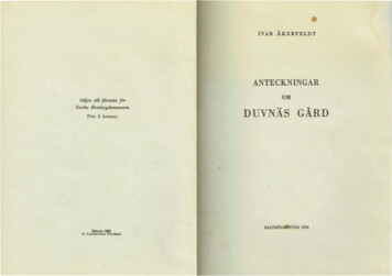
MCMEL Aluminium productsDesign manual for railing systemsDesign Manual forM.C.M.E.L Railing SystemFORDESIGNERS, ENGINEERS, ARCHITECTS,CONTRACTORS & INSTALLERS.www.mcmel.ca1 - USES OF RAILINGSM.C.M.E.L. railing systems are used in homes and inresidential, commercial, and industrial buildings toensure safety on balconies, staircases, mezzanines orall structure over 2 steps.M.C.M.E.L. railing systems consist specifically ofvertical aluminum component parts, posts, whichsupport horizontal and vertical loads. Loads aretransferred to various floors by means of anchoragesor screws. The handrails are the horizontalcomponents connecting the posts that transfer thestatic and dynamic loads (horizontal and vertical) tothem.The spindles are the components that fill the necessaryspace for railing systems. They can be horizontal,vertical, or a combination of both. In M.C.M.E.L.system, these components can be constructed fromdifferent materials such as aluminum, glass panels orhybrid combination.Prepared and approved by:Patrice Austin, ing.Digitech 3D inc.FIGURE 1: THE COMPONENT PARTS OF A RAILINGPrepared by Patrice Austin, eng., Digitech 3D inc. – DI003-001-CON-0001-H1
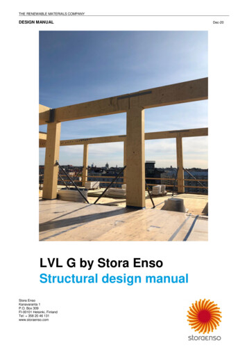
MCMEL Aluminium productsDesign manual for railing systemsAluminium components have several advantageouscharacteristics such as resistance to corrosion and badweather, higher mechanical resistance and arerelatively lightweight. Notably for these reasons,aluminium structure systems are widely used in theconstruction industry for the external perimeters ofbalconies, footbridges, staircases, etc.M.C.M.E.L. is a family business that encourages acreative environment, and is always up-to-date on thenewest industry developments so as to offer innovativeproducts to its clients. The company distinguishes itselfby offering products that are within reach of all budgetswhile recognized for their elegance, durability, ease ofinstallation, and low maintenance.This manual is a design and installation guide forengineers, architects, designers, and installers ofaluminium and wooden platform structure recoveredwith aluminium boards. In this way, installers candetermine the type of beams and spacing betweenthem, the arrangement of component parts comprisedin the system and the specifications for all anchoringas required.2 - TYPES OF M.C.M.E.L DECKING SYSTEMSM.C.M.E.L. offers a decking system including boardsand aluminum structure. It suits many applicationssuch as platforms, decks, mezzanines, balconies andstaircases. The structure can be designed with woodor with M.C.M.E.L aluminum extrusions. Boards arealways fabricated with types of railing systems such asrailings with basket spindles, with double handrails,with plain double handrails, with “Floret” ornamentsand with double handrails with “Gothic” ornament(Figure 2). Handrails, posts and spindles are shown inFigures 3, 4 and 5 respectively.FIGURE 2: M.C.M.E.L RAILING OPTIONSFollowing codes are applicable in Platform systemdesign: www.mcmel.caNational Building code of Canada 2010Ontario Building Code 2012CAN/CSA-S157-05/S157.1-05 (R2010) Strength Design in AluminumPrepared by Patrice Austin, eng., Digitech 3D inc. – DI003-001-CON-0001-H2
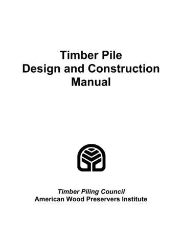
MCMEL Aluminium productsDesign manual for railing systemsFIGURE 3: M.C.M.E.L POST OPTIONSwww.mcmel.caFIGURE 4: M.C.M.E.L SPINDLE OPTIONSNOTCHED POST 1 5/8’’ X 1 3/4’’OVAL SPINDLE 3/4” X 1”POST 2’’ X 2’’SPINDLE 3/4’’ X 3/4’’POST 2 ½’’ X 2 ½’’POST 3’’ X 3’’SPINDLE 3/4’’ X 1’’SPINDLE 1/2’’ X 3/4’’Prepared by Patrice Austin, eng., Digitech 3D inc. – DI003-001-CON-0001-H3
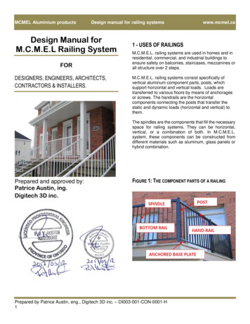
MCMEL Aluminium productsDesign manual for railing systemsFIGURE 5: M.C.M.E.L HANDRAIL OPTIONSwww.mcmel.caPRINCESSE ModelPRINCESSE PLUS ModelHandrail dimensions: 1 5/8" x 1 5/8"Available Posts: 2", 2 1/2" and 3"BARONNE ModelHandrail Dimensions: 1 5/8" x 2 5/8"Available Posts: 2", 2 1/2" and 3"DUCHESSE ModelHandrail Dimensions: 1 5/8" x 2Available Posts: 2", 2 1/2" and 3"ROYAL ModelHandrail Dimensions: 1 5/8" x 2 5/8"Available Posts: 2", 2 1/2" and 3"Handrail Dimensions: 2 3/8" x 2"Available Post: 3"Prepared by Patrice Austin, eng., Digitech 3D inc. – DI003-001-CON-0001-H4
MCMEL Aluminium productsDesign manual for railing systems3 - PHYSICAL PROPERTIESConforming to CSA standard S175-05 calculation ofaluminium structures, the physical characteristics ofaluminium alloys are the following: Modulus of elasticity, E 70,000 MPa Shearing module, G 26,000 MPaLinear coefficient of thermal expansion,α 24 x 10-6 / C Poisson coefficient, ν 0,33Density, ρ 2700 kg/m3The properties of the sections of the component partsused for M.C.M.E.L platform systems are shown inTables 1, 2 and 3. See annex 1 for full sectionproperties for aluminum boards. The mechanical andphysical properties of components of the railing systemare used in order to evaluate the bearing capacity ofthese components against the stress of the externalloads imposed by Codes.Prepared by Patrice Austin, eng., Digitech 3D inc. – DI003-001-CON-0001-H5www.mcmel.ca
MCMEL Aluminium productsDesign manual for railing systems4 - MECHANICAL PROPERTIESMechanical properties of the railing systemcomponents used in M.C.M.E.L products are inaccordance with the CAN/CSA-S157-05/S157.1-05R2010) - Strength Design in Aluminum and appear inTable 3.TABLE 1 - SECTION PROPERTIES OF POSTS (SEE FIGURE 3 FORCOMPLETE SECTION PROPERTIES) (6063-T54 ALLOY)1 ¾’’notched2’’2 0.53)11(0.67)TABLE 3 - SPECIFICATION OF ALUMINUM ALLOY USED FORM.C.M.E.L PRODUCTSFuFytractionFyCompression6063-T5150 MPa(21.8 ksi)110 MPa(16.0 ksi)110 MPa(16.0 ksi)6063-T5(posts)205MPa(29.8 ksi)170 MPa(24.7 ksi)170 MPa(24.7 ksi)6063-T54(posts)230 MPa(33.4 ksi)205 MPa(29.8 ksi)205 MPa(29.8 ksi) 3TABLE 2 - SECTION PROPERTIES OF HANDRAILS (SEE FIGURE 5FOR COMPLETE SECTION 3(in3)6.1(0.381)3.9(0.237)6.7(0.40)4.5(0.274)5.3 red by Patrice Austin, eng., Digitech 3D inc. – DI003-001-CON-0001-H6
MCMEL Aluminium productsDesign manual for railing systems5 - DESIGN PROCEDUREwww.mcmel.caneed not be considered to act simultaneously withthe horizontal load provided for in Sentence (1).5.1 LOADSLoads applied on the railing systems, according toOntario Building Code 2012, are mentioned in chapter4, Rule of Calculation. Loads to consider are theexcess loads due to usage. For model with glass(tempered, heat strengthened and laminated), the loadincludes loads due to the wind. Other loads, such asthe permanent load, snow load, and seismic load, arenegligible because of the low magnitude of these loadsin relation to excess loads due to usage or the wind.5.1.1 SPECIFIED EXCESS LOADS DUE TO USAGEThe excess load from usage per 4.1.5.14 section ofOntario Building Code 2012 following:1) The minimum specified horizontal load appliedinward or outward at the minimum required heightof every required guard shall be,3.4.6.5. Handrails12) Handrails and their supports shall be designedand constructed to withstand the loading valuesobtained from the no concurrent application of,a) a concentrated load not less than 0.9 kNapplied at any point and in any direction for allhandrails, andb) a uniform load not less than 0.7 kN/m appliedin any direction to handrails not located withindwelling units.Please note that 4.1.5.14.1.a cases are excluded fromthis manual and designer shall consult M.C.M.E.L forfurther information.a) 3.0 kN/m for open viewing stands without fixedseats and for means of egress in grandstands,stadia, bleachers and arenas,b) a concentrated load of 1.0 kN applied at anypoint for access ways to equipment platforms,contiguous stairs and similar areas where thegathering of many people is improbable, andc) a distributed load of:i. 0.5 kN/m or a concentrated load of 1.0 kNapplied at any point, whichever governs,for interior residential railings and exteriorresidential railings of a building of 2residences of less;ii. 0.75 kN/m or a concentrated load of 1.0 kNapplied at any point, whichever governs forlocations other than those described inClauses a), b) and c) i.2) Individual elements within the guard, including solidpanels and pickets, shall be designed for a load of0.5 kN applied over an area of 100 mm by 100 mmlocated at any point in the element or elements soas to produce the most critical effect.3) The loads required in Sentence (2) need not beconsidered to act simultaneously with the loadsprovided for in Sentences (1) and (4).4) The minimum specified load applied vertically at thetop of every required guard shall be 1.5 kN/m andPrepared by Patrice Austin, eng., Digitech 3D inc. – DI003-001-CON-0001-H7
MCMEL Aluminium productsDesign manual for railing systems5.2 LOAD COMBINATIONIn cases where the only load is the surcharge due tousage, the Ontario Building Code 2012 defines loadcombination as follows:6 - STRUCTURAL ANALYSESThe load distribution and the structural analysis of thedifferent railing systems are determined in accordancewith the following parameters:Resistance calculation to the ultimate limitstates: 1.5 LDeflection calculation to the serviceability limitstate: 1.0 L For the glass panel included railing, the followingcombinations are considered: 1. Resistance calculation to the ultimate limitstates: max (1.5L, 1.4W)2. Deflection calculation to the serviceability limitstate: max (L, W)L: surcharge, according to the Ontario Building Code2012W: wind load, according to the Ontario Building Code2012It should be noted that the code doesn’t require thecombination of wind loads and surchargessimultaneously.www.mcmel.ca The railing system geometry such as heightand post spacing;Different types of railing system componentssuch as handrails, posts, handrail base, low railand bars;The limit conditions: the type of connection andattachment at the railing system ends as wellas the anchorage stiffness of the posts in theground.The handrail’s continuity, handrail, and postrelative stiffness, the type of spindle, itsspacing, etc.Structural design and verification has been performedaccording CAN/CSA-S157-05/S157.1-05 (R2010) Strength Design in Aluminum, CAN/CSA-A23.3-F04(C2010) – Design of Concrete Structures, CAN/CGSB12.20-M89 Structural Design of Glass for Buildings.According to the Ontario Building Code 2012, thestructural analysis is carried out by the SolidWorkssoftware, a linear analysis to the limit states (SeeFigure 6 for an example of our analysis).Design tables, 4 and 5, are prepared based on theanalysis results considering different posts, thefactored load or real load if guard has been tested, andthe spacing between posts. These calculation tableswere established for a 1.06 m (42 in) railing height.For a different height, the designer should do a morein-depth analysis.According to the 4.1.5.14.2 sentence of OntarioBuilding Code 2012, a 0.5 kN load is horizontallyapplied on the spindles or on the glass railing and it isexerted on 100 x 100mm square. According to ouranalysis, all M.C.M.E.L railing systems can resist anapplied load and it is not necessary for any verificationby the designer in order to fulfill this code requirement.Prepared by Patrice Austin, eng., Digitech 3D inc. – DI003-001-CON-0001-H8
MCMEL Aluminium productsDesign manual for railing systemsFIGURE 6: AN EXAMPLE OF SIMULATION:A) UNIFORM VERTICAL LOAD 1.5 KN/MB) UNIFORM HORIZONTAL LOAD 0.75 KN/MC) CONCENTRATED LOAD OF 1.0 KN(a)(b)(c)Prepared by Patrice Austin, eng., Digitech 3D inc. – DI003-001-CON-0001-H9www.mcmel.ca
MCMEL Aluminium productsDesign manual for railing systemsNON-RESIDENTIAL BUILDINGS7 - DESIGN STAGES7.1 LOADING TYPE DETERMINATIONWe consider two types of minimal specified loads, inaccordance with the 4.1.5.14.1, horizontally appliedtowards the exterior or the interior, on the minimalrequired height of a railing as follows:7.1.1 - 1.0 KN CONCENTRATED LOAD(IN ACCORDANCE WITH 4.1.5.14.1.B)A concentrated load of 1.0 kN applied at any point foraccess ways to equipment platforms, contiguous stairsand similar areas where the gathering of many peopleis improbable.www.mcmel.ca8 - DESIGN STAGE OF RAILING SYSTEMS1) Choose the type of railing system;2) If it is a railing system for:a) a public space (4.1.5.14 CNB2010),consider a usage load of 3 kN/m;b) a residential building of 3 stories or less, oran exterior railing for buildings of 2residences or less (9.8.8.2 CNB 2015),consider a usage load of 0.5 kN/m;c) otherwise 0.75 kN/m;3) According to the load combinations, calculatethe factored load;4) For a factored load of 1.125 kN/m (0.75 kN/m x1,5, where 1.5 is the security factor) andaccording to the type of posts chosen,determine the number of sections (n) and theminimum spacing (s) according to Table 4;5) If the height of the railing is other than 1.06m(42in) or 900 mm (36in), modify the spacingaccording to table 6.7.1.2.A - 0.75 KN/M UNIFORM LINEAR LOAD(IN ACCORDANCE WITH 4.1.5.14.1.C)Uniform load of 0.75 kN/m applied horizontally onrailings.Moreover, for both cases, we separately apply auniform vertical load of 1.5 kN/m on the railing inaccordance with sentence number 4.1.5.14.4 of theOntario Building Code. Also, a 0.9 kN concentratedload or a 0.7 kN/m load divided in two vertical andhorizontal directions on the handrails, only for thehandrail design in accordance with 3.4.6.5.12 sentenceof Ontario Building Code 2012.Prepared by Patrice Austin, eng., Digitech 3D inc. – DI003-001-CON-0001-H10
MCMEL Aluminium productsDesign manual for railing systemsFIGURE 7: M.C.M.E.L HANDRAIL OPTIONSwww.mcmel.caTABLE 4 – LOAD NON-FACTORED 0.75 KN/MTABLE 4 - REGULAR HANDRAIL - SPACING BETWEEN POSTS AT0.75 KN/MNumber of sections (ns)2’’2 (84)2030(80)Height of 42”1524(60)1372N 2 (tested)(54)1219N 3 (simulated)(48)Height of 36”N 1 (tested)STANDARD HANDRAILSpacingbetween theposts (s)N 1 (simulated)[mm(in)]N 2 (simulated)N 3 (simulated)1829(72)1676(66)1372(54)TABLE 4.2 - CONTINUOUS HANDRAIL WITH SPINDLES (2 POSTSWITH NOCHED 1 5/8 X 1 ¾ POST BETWEEN) AT 0.75 KN/MNumber ofsections (ns)Dist.2 ’’2 ½’’3’’1524(60)3048Post toPost(120)1524Post tonotched(60)3048Post toPost(120)Height of 657(144)1829(72)3657(144)Height of 42”Spacingbetween theposts (S)[mm(in)]N 1(tested)N 2(simul.)Spacingbetween theposts (s)[mm(in)]CONTINUOUS HANDRAIL (Fig. shows onenoched, but maximum of two noched 1 5/8 X1 ¾ can be installed between Posts)N 1(simul.)N 2(simul.)Prepared by Patrice Austin, eng., Digitech 3D inc. – DI003-001-CON-0001-H11Post tonotchedPost tonotchedPost toPostPost tonotchedPost toPost
MCMEL Aluminium productsDesign manual for railing systemsGLASS GUARDRAILS:www.mcmel.caFIGURE 8: DESIGN DE SYSTÈMES DE RAMPES POURMCMEL also proposes glass panel guardrails. Theseguardrails meet the requirements of the NationalBuilding Code, for resistance and deformation underloads impose by Code. The tempered glass used is 6mm thick. The tempered glass complies with to theCAN/CGSB-12.1 M90 standard. The maximumacceptable length of guardrails is presented in thefollowing table 4.3PATIOSTABLE 4.3 - CONTINUOUS AND STANDARD HANDRAIL WITHGLASS (2 POSTS WITH NOCHED 1 5/8 X 1 ¾ POST BETWEEN)AT 0.75 KN/MNumber ofsections (ns)Dist.2 ’’2 ½’’3’’1524(60)3048Post toPost(120)1524Post tonotched(60)3048Post toPost(120)Height of 657(144)1829(72)3657(144)Height of 42”Spacingbetween theposts (S)[mm(in)]N 1(tested)N 2(simul.)Spacingbetween theposts (s)[mm(in)]N 1(simul.)N 2(simul.)Post tonotchedPost tonotchedPost toPostPost tonotchedPost toPostIMPORTANT NOTE:The handrail not supported by a foot support is alwayslimited to 72 inches (1.8 m). A foot support is a spindleelongated to be attached to the floor.Prepared by Patrice Austin, eng., Digitech 3D inc. – DI003-001-CON-0001-H12
MCMEL Aluminium productsDesign manual for railing systemsRESIDENTIAL BUILDINGS9 - DESIGN STAGES9.1 LOADING TYPE DETERMINATIONWe consider two types of minimal specified loads, inaccordance with the 9.8.8.2 sentence of the OntarioBuilding Code, horizontally applied towards the exterioror the interior, on the minimal required height of arailing as follows:9.1.1 - 1.0 KN CONCENTRATED LOAD(IN ACCORDANCE WITH 9.8.8.2)A concentrated load of 1.0 kN applied at any point foraccess ways to equipment platforms, contiguous stairsand similar areas where the gathering of many peopleis improbable.www.mcmel.ca10 - DESIGN STAGE OF RAILING SYSTEMS1) Choose the type of railing system;2) If it is a railing system for:d) a public space (4.1.5.14 CNB2010),consider a usage load of 3 kN/m;e) a residential building of 3 stories or less, oran exterior railing for buildings of 2residences or less (9.8.8.2 CNB 2015),consider a usage load of 0.5 kN/m;f) otherwise 0.75 kN/m;3) According to the load combinations, calculatethe factored load;4) For a factored load of 0.75 kN/m (0.50 kN/m x1,5, where 1.5 is the security factor) andaccording to the type of posts chosen,determine the number of sections (n) and theminimum spacing (s) according to Table 5;5) If the height of the railing is other than 1.06m(42in) or 900 mm (36in), modify the spacingaccording to table 6.9.1.2 – 0.5KN/M UNIFORM LINEAR LOAD (INACCORDANCE WITH 9.8.8.2)Uniform load of 0.5 kN/m applied horizontally onrailings.Moreover, for both cases, we separately apply auniform vertical load of 1.5 kN/m on the railing inaccordance with sentence number 9.8.8.2 of theOntario Building Code. Also, a 0.9 kN concentratedload or a 0.7 kN/m load divided in two vertical andhorizontal directions on the handrails, only for thehandrail design in accordance with 3.4.6.5.12 sentenceof Ontario Building Code 2012.Prepared by Patrice Austin, eng., Digitech 3D inc. – DI003-001-CON-0001-H13
MCMEL Aluminium productsDesign manual for railing systemsFIGURE 9: M.C.M.E.L HANDRAIL OPTIONSwww.mcmel.caTABLE 5 – LOAD NON-FACTORED 0.50 KN/MTABLE 5.1 – REGULAR HANDRAIL - SPACING BETWEEN POSTS AT0.50 KN/MNumber of sections(ns)2’’2 2747(108)2540(100)Height of 42”Spacingbetweenthe posts(s)[mm(in)]STANDARD HANDRAILSpacingbetweenthe posts(s)1905(75)1715N 2 (simulated)(68)1524N 3 (simulated)(60)Height of 36”N 1 (tested)N 1 (simulated)N 2 (simulated)[mm(in)]N 3 (simulated)2286(90)2095(83)1829(72)TABLE 5.2 – CONTINUOUS HANDRAIL WITH SPINDLES (2POSTS WITH NOCHED 1 5/8 X 1 ¾ POST BETWEEN) 0.50 KN/MNumber ofsections (ns)Dist.2 ’’2 ½’’3’’1524(60)3048Post toPost(120)1524Post tonotched(60)3048Post toPost(120)Height of 657(144)1829(72)3657(144)Height of 42”Spacingbetween theposts (S)[mm(in)]N 1(tested)N 2(simul.)Spacingbetween theposts (s)[mm(in)]CONTINUOUS HANDRAIL (Fig. shows onenoched, but maximum of two noched 1 5/8 X1 ¾ can be installed between Posts)N 1(simul.)N 2(simul.)Prepared by Patrice Austin, eng., Digitech 3D inc. – DI003-001-CON-0001-H14Post tonotchedPost tonotchedPost toPostPost tonotchedPost toPost
MCMEL Aluminium productsDesign manual for railing systemsGLASS GUARDRAILS:MCMEL also proposes glass panel guardrails. Theseguardrails meet the requirements of the NationalBuilding Code, for resistance and deformation underloads impose by Code. The tempered glass used is 6mm thick. The tempered glass complies with to theCAN/CGSB-12.1 M90 standard. The maximumacceptable length of guardrails is presented in thefollowing table 5.3www.mcmel.caFIGURE 10: HANDRAIL SYSTEM – DESIGN FORBANISTERSTABLE 5.3 – CONTINUOUS AND STANDARD HANDRAIL WITHGLASS (2 POSTS WITH NOCHED 1 5/8 X 1 ¾ POST BETWEEN)AT 0.50 KN/MNumber ofsections (ns)Dist.2 ’’2 ½’’3’’1524(60)3048Post toPost(120)1524Post tonotched(60)3048Post toPost(120)Height of 657(144)1829(72)3657(144)Height of 42”Spacingbetween theposts (S)[mm(in)]N 1(tested)N 2(simul.)Spacingbetween theposts (s)[mm(in)]N 1(simul.)N 2(simul.)Post tonotchedPost tonotchedPost toPostPost tonotchedPost toPostIMPORTANT NOTE:The handrail not supported by a foot support is alwayslimited to 72 inches (1.8 m). A foot support is aspindle elongated to be attached to the floor.Prepared by Patrice Austin, eng., Digitech 3D inc. – DI003-001-CON-0001-H15
MCMEL Aluminium productsDesign manual for railing systemswww.mcmel.ca11 - HEIGHT MODIFICATION COEFFICIENTS12 - POST ANCHORINGIn the majority of cases, the height of the railing is42 inches. In the cases where the height is different,railing height modification coefficients such as thoselaid out in Table 6 can be used:The anchorage of the base of the posts to the floor ofthe component part is very important to ensure anadequate performance of a railing system. Accordingto the type of floor (concrete or wood) and the type ofrailing system, it is essential to put an adequateanchorage system into place.TABLE 6 - RAILING HEIGHT MODIFICATION COEFFICIENTSHeightHeight coefficientsfor loads due tousageHeight coefficientsfor loads due towind500 mm(20 po)2.1600 mm(24 po)1.75700 mm(28 po)1.50800 mm(32 po)1.30900 mm(36 po)1.201 067 mm(42 po)1.01.01 100 mm(44 po)0.950.901 200 mm(48 po)0.880.761 300 mm(52 po)0.800.651 400 mm(56 po)0.750.561 500 mm(60 po)0.700.502 000 mm(78 po)0.540.30It is to be noted that the resistance and good structuralperformance of a railing depend not merely on carriercomponent parts such as posts and handrails, but inlarge part to the anchoring of the posts to the floorsurface. In the case of awooden floor, it is also necessary to ensure that thefloor in question is of a sufficient rigidity to bear theloads imposed by the railing posts. Here are theminimum recommended anchorages:Prepared by Patrice Austin, eng., Digitech 3D inc. – DI003-001-CON-0001-H16
MCMEL Aluminium productsDesign manual for railing systemsFIGURE 11: REQUIRED ANCHORAGES FOR ACONCRETE FLOOR – RAILING SYSTEMNotched post 1 ¾” x 1 ¾”4x Titen ¼” x 2 ¾”Galvanized steel anchorswww.mcmel.caTABLE 7 - ULTIMATE LOADS FOR ANCHORS AND SCREWTESTING IN CONCRETEPOST3’’ x 3”Anchor4 x Titan ¼ X 2 ¾Ultimate Horizontal loadapplied at height 1067mm(42’’) of the post (accordingto tests carried out by themanufacturer M.C.M.E.L)1.67 kN (374 lbs)Failure modeBottom screws(connecting post andbase plate) failureUltimate Horizontal loadapplied at height 1067mm(42’’) of the post 1.65kN (370 lbs)Failure mode (Not govern)Anchor pullout and/orconcrete failurePost - 3 in x 3 in4 x Titen ¼ X 2 ¾Galvanized steel anchorsPrepared by Patrice Austin, eng., Digitech 3D inc. – DI003-001-CON-0001-H17
MCMEL Aluminium productsDesign manual for railing systemsPrepared by Patrice Austin, eng., Digitech 3D inc. – DI003-001-CON-0001-H18www.mcmel.ca
MCMEL Aluminium productsDesign manual for railing systemsPrepared by Patrice Austin, eng., Digitech 3D inc. – DI003-001-CON-0001-H19www.mcmel.ca
MCMEL Aluminium productsDesign manual for railing systemsPrepared by Patrice Austin, eng., Digitech 3D inc. – DI003-001-CON-0001-H20www.mcmel.ca
MCMEL Aluminium productsDesign manual for railing systemsPrepared by Patrice Austin, eng., Digitech 3D inc. – DI003-001-CON-0001-H21www.mcmel.ca
MCMEL Aluminium productsDesign manual for railing systemswww.mcmel.caFIGURE 12: REQUIRED ANCHORAGES FOR AWOODEN FLOOR – BALUSTRADE SYSTEMWhen the railing is used on deck frame maiden withwood, composite or solid PVC, the anchors must beinstalled in transverse 2” x 6” (one of these materials)beams between the main beams of the structure. Thefollowing images show how to position these beams.The image below shows the position of the posts andthe transverse 2” x 6”x beams.For every type of post4 x Lag screw 5/16 X 4 inGalvanized steel2” x 6” spruce beam min. (vertically)Prepared by Patrice Austin, eng., Digitech 3D inc. – DI003-001-CON-0001-H22
MCMEL Aluminium productsDesign manual for railing systemsFIGURE 13: ANCHORING PLATES CONFIGURATION –FOR ALL TYPES OF FLOORIMPORTANT NOTE: it is very important to makesure that posts are install in correct orientation to insurea maximal resistance of the guardrail. In every case,anchoring plates should be oriented perpendicularly tothe direction of the handrail (see figure 13). Forcorners, the orientation has no importance becausethere is an handrail in both directions, as shown in thefigure 13. These orientations should be respected forall types of floor.Prepared by Patrice Austin, eng., Digitech 3D inc. – DI003-001-CON-0001-H23www.mcmel.ca
MCMEL Aluminium productsDesign manual for railing systems13 - REQUIREMENTS OF STANDARDCNB2010 (Reference)The National Building code (CNB 2010, Chapter 3concerning protection against fire, safety of occupantsand accessibility, and Section 3.4 concerning therequirements relative to emergency exits):3.4.6.5 HANDRAILSStaircases must be equipped with a handrail on at leastone side and, if its size is 1,100 mm or more, with ahandrail on each side.1) If the required size for a ramp or a flight of stairs isgreater than 2,200 mm, it is necessary to plan forone or several uninterrupted intermediary handrailsspanning from one landing to the other with theinterval between two handrails being no greaterthan 1,650 mm.2) The handrails must be easy to grasp along theirentire length and:a) If they have a circular section, must have adiameter of at least 30 mm and at most 43 mm;orb) If they have a non-circular section, must have aperimeter of at least 100 mm and at most 125mm and a transverse section of which the largestdimension is at most 45mm.3) The height of the staircase handrail and railing mustbe measured perpendicularly from the top of thehandrail:a) To a tangent at the nosing of the staircase stepsserviced by the handrail (see note A-9.8.7.4.); orb) to the surface of the ramp, of the floor or of thelanding serviced by the handrail. Subject to thequalifications of Paragraphs 6) and 7), staircasehandrails and railings must have a height:i. of at least 865 mm; andii. of at most 965 mm.4) It is not mandatory for handrails installed in additionto the minimum required handrails to conform toParagraph 5).5) When railings are required, landing handrails mustnot be higher than 1,070 mm.6) Except when it is interrupted by change-of-directionrailings or by door openings, at least one handrailmust continue for the entire length of the staircaseor ramp, including landings (see Appendix A).www.mcmel.ca7) Handrails must finish in a way that does not impedethe passing of pedestrians or constitute a risk (seenote A-3.4.6.5 8).8) Staircases and ramps must have at least one sidehandrail that extends horizontally for at least 300mm at each end (see note A-3.4.6.5. 8).9) The clearance between handrails and all surfaceslocated behind them must be:a) at least 50 mm; orb) 60 mm if the surface located behind the handrailsis rough of abrasive.10) Handrails and their supports must be calculatedand built to resist the highest of the following loads:a) a concentrated load of at least 0.9 kN appliedat any given point and in any given direction,for all handrails; orb) a uniform load of at least 0.7 kN/m applied inany given direction, for handrails that are notlocated inside a building.11) It is necessary to install handrails on both sides ofa ramp.3.4.6.6. RAILINGS1) All emergency exits must be protected on each sideby a wall or a firmly attached railing.2) Subject to the qualifications in Paragraph 4), railingsfor emergency exit stairways must be of a height ofat least 920 mm measured perpendicularly from thenosing of the step to the top of the railing, and of atleast 1,070 mm to the periphery of the landings.3) Railings for emergency exit ramps and theirlandings must be of a height of at least 1,070 mmmeasured perpendicularly from the surface of theramp to the top of the railing.4) Railings for outdoor staircases and landings of morethan 10 m above the adjacent ground must be of aheight of at least 1,500 mm measuredperpendicularly from the surface of the landing orthe nosing of the step to the top of the railing.5) The openwork sections of the railing of anemergency exit must not allow the passage of aspherical object of more than 100 mm in diameter,unless it can be demonstrated that openworksections with dimensions greater than this limit donot present a risk.6) Stairwell windows with a support of at least 900 mmhigh in relation to the nosing of the step or a heightof at least 1,070 mm in relation to a landing must:a) be protected by a railing whose upper part islocated:Prepared by Patrice Austin, eng., Digitech 3D inc. – DI003-001-CON-0001-H24
MCMEL Aluminium productsDesign manual for railing systemsi. at a height of about 900 mm in relation to aline linking the nosing of the steps or;ii. at least 1070 mm above the landing; orb) be subject to and designed to resist lateral loadsfor railings and walls mentioned in Articles4.1.5.1.4. and 4.1.5.1.6.7) Railings must be designed in such a manner that nocomponent part, support or opening situatedbetween 140 and 900 mm above the level protectedby these railings thereby permits climbing, unless itcan be demonstrated that the position anddimension of the openwork sections that surpassthis limit do not pre
design: National Building code of Canada 2010 Ontario Building Code 2012 CAN/CSA-S157-05/S157.1-05 (R2010) - Strength Design in Aluminum 2 - TYPES OF M.C.M.E.L DECKING SYSTEMS M.C.M.E.L. offers a decking system including boards and