Transcription
ME 423 ENGINEERING DESIGN VIIPHASE III – FINAL PROPOSAL & DESIGNRobovac (Autonomous Robotic Vacuum Cleaner)A SENIOR REPORTME 423 GROUP 1Juan GamarraDiego MolinaJetmir PalushiRaymond PerezJoseph SeborowskiADVISOR: Jae ChungSTEVENS INSTITUTE OF TECHNOLOGYCastle Point on HudsonHoboken, NJ 07030December 7, 2006
Table of ContentsProject background . 4Objective and Mission statement . 5Conceptual Designs . 6State of the Art Improvements . . 7Reshaping . 7Mapping . 8Sensors . 9Dirt 9Obstacle . 9Incline/Decline . 10Mapping . 10Programming . 11Total Cost of Sensors 11Power Consumption 11Design . 12Case Optimization . 12Brush Optimization . 13Battery 13Selected Battery . 15Motors . 16Blowers . 17Gears .17Power loss due to friction . 18Cleaning . 18Appendix . 21Figure 1 Stair Cleaner . 21Figure 2 Water Filtration . 22Figure 3 Dirt Sensosr . 23Figure 4 RF Transmitter/Encoder . 24Figure 5 Sharp Engine Card . 24Figure 6 Algorithm . 25Figure 7 Von Mises Stress . 30Figure 8 Mass and Volume Optimization . 31Figure 9 Final Bottom Piece . 32Figure 10 Brush Optimization . 33Figure 11 Brush Configuration . 34Figure 12 Infrared Sensors . 35Figure 13 Bumper . 35Figure 14 Motor Mount . 36Figure 15 Microcontroller . 37Figure 16 Battery . 38Figure 17 Blower . 39Figure 18 Display Screen . 40Figure 19 Wireless Transmitter . 412
Figure 20 Battery Analysis . 42Figure 21 Main Brushes . 43Figure 22 Gear Efficiencies . 43Figure 23 Suction Motor . 44Figure 24 Dusk Bin . 45Figure 25 Reynolds Number, Velocities, Densities, and Pressure . 46Figure 26 Steam Version of System . 46Figure 27 Flow Rate . 47Figure 28 Compressibility Factor . 47Figure 29 Steam Heat Capacity Ratio . 48Figure 30 Selection of Materials, Piping 48Figure 31 Absolute Roughness . 49Figure 32 Minor Loss due to Flush Entrances . 49Figure 33 Minor Loss due to Exhaust Port . 50Figure 34 Minor Loss due to Stab in Type Branch . 50Figure 35 Losses due to two 90 Degree Bends . 51Figure 36 Calculations . 523
Project BackgroundThe first Roomba was thirteen inches in diameter and roughly four inches high. TheRoomba used a large bumper mounted on the front of the unit to detect any walls orobjects in its path. The robot was equipped with infrared sensors on the top front center.It also used a virtual wall that transmitted infrared to the unit so it does not attempt toclean other rooms and get lost.The first prototype consisted of three settings. The settings consisted of setting a roomsize, small, medium and large. Roomba’s first feature at the time was the ability to detectwhether or not there was enough power for it to clean the room size you chose. Howeveras technology has gotten more sophisticated so has the Roomba. The Roomba can nowdetect room sizes without a user input.The first Roomba operated on internal nickel metal hydride batteries that required beingrecharged regularly from a wall plug. The newest generations of Roomba’s now have selfcharging features. The Roomba takes about six to eight hours to recharge itself. iRobotoffers a fast recharging pack which can recharge in 3 hours at the price of 60.The newer generations Roomba’s are virtually completely automated. The user has to justplace the Roomba on the floor and choose clean, spot, or max. The clean button willclean a room. Spot clean will clean an area. Max will clean until the battery runs out. TheRoomba also now has an automatic scheduler accessory.Electrolux Trilobite and Samsungs robots now have the ability to map out rooms they arecleaning. Roomba, unlike Electrolux Trilobite, relies on simple algorithms such as spiralcleaning.An MIT researcher and iRobot CTO Rodney Brooks’ philosophy that robots should belike insects, equipped with simple control mechanisms tuned to their environments. Theresult is that although Roombas are effective at cleaning rooms, they take several times aslong to do the job as a person would, usually covering some areas many times and otheronly once or occasionally not at all.11http://en.wikipedia.org/wiki/Roomba4
ObjectiveIdentify and design an autonomous robot that will assist people at home who are too busyfor daily or weekly floor cleaning, especially for family’s with children. In particular forthe elderly who live by themselves and do not have the strength or ability to clean.Robotic vacuum cleaners in the market are expensive and inefficient in terms of cleaningtime and cleanness. The goal is to design an omni directional platform with infraredsensors, wireless sensors, bumpers, ultrasound, reshape, and four bristle brushes on everyside to improve the cited cleaning performance problems.2Mission Statement: Robotic Vacuum CleanerProduct Description Key Business Goals Primary MarketsSecondary MarketsAssumptions and ConstraintsStakeholders2 Omni directional, cleans efficiently, usesinfrared sensors, self charging, bumpers,wireless, ultrasound, reshapeEnvironmentally friendlyBe the leader in economic robotic vacuumcleanersFirst prototype to released in mid AprilProduct introduced in fourth quarterDecember 2007Capture 20% of robotic vacuum cleanersales by 2009First product serves as a platform for highend robotic vacuum cleanersInclude a two year full warranty with everyvacuum soldNew robotic vacuum cleaner usersMiddle – class families ( 25,000 100,000)Average size homes (2300 sq. ft.)Existing robotic vacuum cleaner motorProfessional cleaning servicesSchools, businessesUpper class families ( 100,000 – unsp.)New product platformRechargeable battery technologySelf chargingSelf dockingInfrared systemWireless systemSome devices and parts will bemanufactured outside of the United Statesto meet the sales objectivePurchasers and usersManufacturing operationsService operationsDistributors and resellersSales forceME 423 Mechanical Engineering Design VII Project Descriptions Fall 20065
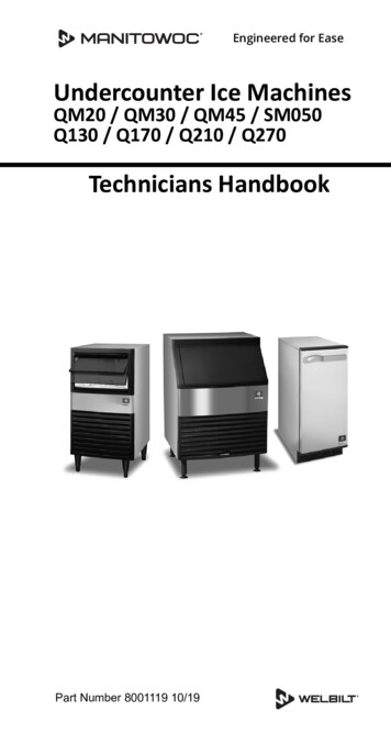
Conceptual DesignsAll robotic vacuum cleaners that are out in the market today are disk shaped. Theproblem with that is that they cannot clean the corners of rooms very well. Since ourmain objective was to improve the overall cleaning efficiency, we decided to change theshape from a circle to a square. The square design will allow our vacuum to clean thecorners of rooms better.Disk Shaped DesignRedesigned Square ShapedOne of our first ideas was to make our vacuum able to clean stairs since no roboticvacuum out in the market today does that. The vacuum would be able to hoist itself upthe stairs and clean each stair. We got rid of this design because it did not meet any ofour customer needs or concerns. Figure 1 in AppendixA customer concern was the dusk bin. You had to remove and empty out the dusk binyourself once the vacuum was done cleaning. The dusk wasn’t sealed well in the bin andwhen you would take it out of the vacuum, if you were not careful the dusk would comeout of the bin and fall on the carpet. To prevent this from happening, an idea was tomake a water filtration system. The dirty air would pass through the water and the HEPAfilter and come out as clean air. This design didn’t workout because we weren’t sure ifwe can completely contain the water and not allow the water to escape and go into theelectrical systems of the vacuum. Figure 2 in Appendix6
State of the art review and improvements:Based on the information gathered the team broke down the areas of improvement to fiveSections: Shape, Sensors, Batteries, Suction, and Motors. Below we will examine thetechnology and state of the art aspects of the Robovac as opposed the competitors whichwere researched.ReshapingThe typical shape of a robotic vacuum cleaner is a disk. The reasons they are disk-shapedis because of mobility. They can maneuver through tight spaces and still cleaneffectively. When they bump into a wall or piece of furniture, since it is a circle, it caneasily turn around and adjust its position and continue cleaning. The major problem withthe vacuum being a circle is that it cannot clean the corners of rooms very well. If youchange the shape to a square, then the vacuum can get into the corners and clean better,but there are no square robot vacuums. The reason why there are no square vacuums isbecause of the pointed edges. As the vacuum is going along and cleaning it will bumpinto obstacles and then re-position itself. As the vacuum is re-positioning itself, the edgescan come into contact with obstacles and will waste more time re-positioning itselfinstead of cleaning. Our new design for the shape of the vacuum is going to be a squarewith rounded edges.Having a square will get the corners to be cleaned much better and the rounded edges willallow the vacuum to have the same mobility to work its way through tight spots. We willbe compromising some mobility in changing the shape to a square with rounded edges.The circle shaped vacuums right now can easily readjust when it comes in contact withan obstacle especially in tight spots. If the vacuum is cleaning under a chair with 4 legs, acircle shaped vacuum can make its way under the chair and clean around the legs withoutmuch difficulty. The same goes for table, couch and bed legs. The corners of a roomdon’t even get cleaned because it can’t get into the corners all the way before bumpinginto the wall.The square shaped with rounded edges will be able to clean corners better and also alongwalls. The only drawback is that it will lose some mobility and maneuverability. It isimpossible to be able to make the robot clean corners 100%. It will never be able to cleancorners and along walls perfectly. Having a square with rounded edges is the best designfor our vacuum. It will be able to clean corners and along walls better then a circle shapedvacuum. We want to keep the area of the square vacuum about the same as the circle.Also, keeping it the same height as the Roomba will allow our vacuum to clean undermost beds, chairs and couches. The height of couches, beds, desks, etc, varies in size. Thevacuum will either be able to or won’t be able to clean under them. The height of thefurniture off the ground is about an inch from the ground or as much as 6 inches from theground. If the vacuum is able to get under the couch or bed, it probably won’t get stuckunder there. It should be able to make its way underneath the furniture, clean and then getout from under there without a problem.7
Keeping it roughly the same area and height of today’s robot vacuums will allow it toclean under furniture. The cleaning equipment and wheels will be able to fit inside thesquare shape with no problems. Adjustments will need to be made as to where thebrushes, wheels and vacuum need to placed.Most robotic vacuum cleaners are made out of hard plastic. Customers are worried aboutthe longevity of the product. The plastic edge bumps into furniture and walls frequently.The plastic that we are going to use is acrylonitrile butadiene styrene. ABS is athermoplastic used to make light, rigid, molded products and is known for its resistance,toughness and electrical insulation properties. ABS is commonly used in the electricaland electronics industries because it is not only highly scratch and wear resistant but alsodecorative and easy to maintain. The cost of producing ABS is roughly twice the cost ofproducing polystyrene, but is worth it due to its hardness.MappingOne of the major disadvantages of the current robots is that in order to find theway back to the battery charger, the battery charger must be located to the wall or else therobot won't be able to charge itself in an automated fashion. Even when the charger isright on the wall the robot will still miss the battery charger in some cases because itscoordinates have deviated while it was cleaning the room. On the other hand we plan toimprove our robot, the RoboVak, by introducing a totally different concept from thecurrent technology that is being used in market. Our technology will allow us to placethe battery charger anywhere on the room and it is guaranteed that the robot will find thecharging location. Our team came up with several ideas:1) Keeping track of the coordinates while the robot is cleaning the room and usethese coordinates to track back the path when the robot needs to be charged.2) Use a random algorithm to approximate the location of the battery charger, anduse sensors to find the exact location.3) Use a wireless system that will keep track of the location of the battery charger sothe robot can find it in a finite time when it needs to be recharged.4) Use directional radio antennas between the robot and the home to guide the roboton the direction of the battery charger.Idea number two was eliminated for the following reasons:a) It takes a long time for the robot to find the charger and the battery might becompletely discharged before the robot locates the home.b) It does not increase the probability of finding the home more frequently than thecurrent products.The other three ideas were picked for further evaluation.8
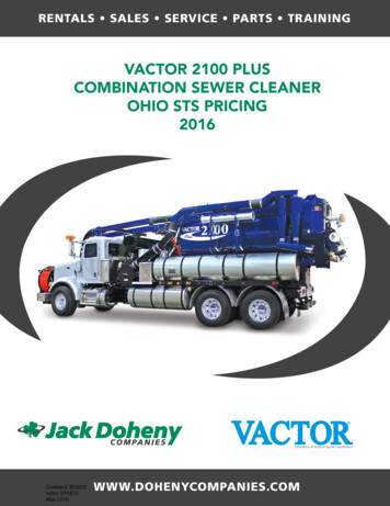
SensorsDirt Sensors Figure 3 in AppendixThe reason why we must be able to detect the amount of dirt entering the vacuum isbecause dirtier areas must be cleaned for a longer time. If we do not clean these dirtierareas longer by decreasing the speed of the vacuum than the room will not be completelycleaned at the end of the cleaning procedure.There are two potential ideas how to detect the amount of dirt entering the suction. Firstone is to use an ultrasonic sensor. Basically we mount two sensors on the opposite sidesat the dirt entrance and monitor the amount of dirt using a voltmeter circuit. See thediagram below for schematics. The other idea is to use a wrap a piece of wire around thesuction in the form of a solenoid and monitor the electric field induced on this solenoid.The dirt content will change the conduction of the electromagnetic field inside of thesolenoid and therefore we can detect higher content of dirt from lower ones.Obstacle SensorsSince most of the sensors our team researched would measure either very close distancesor greater than 2" we decided that the best way to go for detecting the wall and otherobstacles that the robot will hit is using microscopic bumpers which can be small and anyshape we want them to be in order to minimize the amount of space on the robot. Thecircuit diagram of a bumper is given below:Circuit representation of the bumper switchThe bumper is represented by the open switch (S1) meaning that the robot hasn't hitanything. When the bumper is closed the current starts to flow from -5V to Groundtherefore the digital input will change its value from logic 0 to logic 1 and the softwarewill detect an obstacle and proceed to another loop and try to eliminate whatever therobot has hit. Building this circuit will cost approximately 1 .9
Rapid Incline/Decline sensorsSharp GP2Y0A21YK infrared sensorDetects distance from 10cm-80cm. This infrared can be used to detect the stairs andsteep inclines, when there is a sudden changed on the height from where the sensor ismounted to the floor. The only concern is that the distance from the floor to thesensor must be equal or greater than 4" for this sensor to work accurately. The sharpGP2Y0A21YK is priced at 10 .Mapping sensorsRF transmitter/receiver light sensors to guide the robot when it runs out of batteryPre-made TransmitterOperates in excess of 300feet, a receiver of this kind can be purchased for decoding theencoded digital signal on the analog wave. Easy to install, and very small so it can bemounted anywhere on the body of the robot. The only part needed is the antenna. Thissensor transmitter is priced at 16.66 . Figure 4 in Appendix10
ProgrammingThe schematic below shows how all the sensors are integrated on the programmedprinted circuit board.The fact that we have so many sensors to facilitate the navigation of the robot we had toselect a microcontroller that had a lot of general purpose input/output pins. These pinswill be used to hook up all the sensor inputs to monitor their voltage or current drop. Themost feasible card for the RoboVAC project seemed the Sharp Engine Card that has 64I/O pins and meets our requirements. A diagram of the card. Figure 6 in AppendixThe algorithm can be seen in Figure 6 of the Appendix.Total Cost of Sensors for mappingQuantitySensorPrice1Polaroid Sensor19 10Bumper Switches10 5Sharp Infrared50 2RF transmitter/receiver64 TOTAL143 Power ConsumptionSensorWall 5mW10mW7.5mWTotal0.2W0.7W0.01W15mW0.925W11
DesignCase Optimization:The material being used for the case and most of the robot is ABS because it is easilymanufactured, cheap and it can be injection molded. Acrylonitrile butadiene styrene, orABS, is a common thermoplastic used to make light, rigid, molded products such aspipes, golf club heads. The styrene gives the plastic a shiny, impervious surface. Thebutadiene, a rubbery substance, provides resilience even at low temperatures. ABS can beused between 25 C and 60 C.Mechanical Properties of ABSTensile Strength,Ultimate29.8 - 65 MPa4320 9430 psiTensile Strength, Yield29.6 - 65 MPa4290 9430 psiTensile Modulus1.79 - 3.2 GPa260 - 464 ksi1.606 5.903 GPa233 - 856 ksiAverage 2.4GPa; GradeCount 12247.8 - 107 MPa6930 15500 psiAverage 71.8 MPa;Grade Count 120Flexural ModulusFlexural Yield StrengthAverage 41.5 MPa;Grade Count 79Average 44.8 MPa;Grade Count 143Average 2.4GPa; GradeCount 141The outer case of the Robovac was originally designed to be .3 inches thick to support itsouter walls. The weight of all the components inside of the Robovac will not exceed 15lb. In order to correctly optimize the design a factor of safety of an additional 5 lb wasadded. To accurately simulate the load the design analysis was run with a distributed loadof 20 lb over the bottom surface. The original analyze was run at a thickness of .3 incheshowever that was over designing hence adding to material cost. The analysis gave thegroup a max Von Mises stress of 1.0891e-1. The results can be seen in Figure 7 of Appendix.The material that was chosen can withstand a lot more stress then applied. A Solidworksmass and volume optimization was performed to lessen the amount of material used. Theteam found that a wall thickness of .15 was acceptable thickness. The new analysis canbe seen in Figure 8 of Appendix.The final design consists of a bridge for added support. The final bottom piece can beseen in Figure 9 of Appendix.12
Brush Optimization:The brushes that will be used will be expected to rotate at 4500 RPM . This transmittedcentrifugal force will translate to a lot of stress on the rod. A finite element analysis wasperformed to measure its Von Mises stress and its max displacement. The max VonMises stress on the assembly is 3.765 psi , which is reasonable because we are usingABS. It has a very high plastic deformation threshold. Below you will find the Von Misesstress and deformation analysis. Figure 10 in Appednix The brush configurations can be seen inFigure 11 in Appendix. The components consist of the infrared sensors Figure 12, the bumper Figure13, the motor mount Figure 14, the microcontroller Figure 15, the battery Figure 16, theblower Figure 17, the display screen Figure 18 and the wireless transmitter Figure 19.BatteryObjective:The main focus of the battery part of the project is to provide enough power to allthe components of the robot while lasting long enough to clean an average room withouthaving to recharge. The battery should not add on excessive cost to the overall unit baseprice.Customer Needs:Based on customer research obtained through questionnaires and market researchthe following have been identified as the key focal points for the battery:Clean room on a single chargePower numerous motorsPower sensorsShort recharge timeFull-charge current cutoffMinimize memory effectRecharge docking station13
Benchmark Data:The following represents the battery specifications for current robotic vacuumcleaners on the market. In order to be able to compete successfully with the competition,the RoboVac must be able to at least meet and even exceed these specifications. 30 – 45 minutes run time7 hour recharge time w/out rapid charger3 hour recharge time w/ rapid charger (expensive option)14.4 – 18 Volts 3 Amp-hoursNiMH or NiCd chemistryRecharge docking stationSelection Process:In selecting a battery there are many factors that need to be taken intoconsideration assuring that all the needs are meant in a feasible manner. Most batterypacks are comprised of individual battery cells connected in series but a connector tab.ChemistryCost WeightTempCycle Shelf Life Volts( oC)Life (months) per cellLead Acid Very Heavy -65 to 80 300 122.0Nickel Cadmium Heavy-20 to 65 500 61.2Nickel Metal Hydride Moderate -10 to 65 500 121.2Lithium Ion Light-20 to 60 500 123.7Lithium Polymer Light-20 to 60 500 123.7Minimal Requirements:14
The following lists the minimum requirements necessary for the battery to have inorder to meet the needs of the RoboVac. The battery analysis is in Figure 20 of Appendix¾¾¾¾18 volts3000 milli-amp hour capacitymax 12 in 2 areamax 50 (not including charger)Selected Battery:Price: 23.95Specifications:Voltage (V)Capacity (mAh)Cell TypeQuantityChemistryShort Time Discharging Rate (A)Continuous Usage Discharging Rate(A)Dimensions (in.)Weight (oz.)245000AA20NiMH3.51.86x2x1.211Selected Charger:Price: 12.95Specifications:Voltage (V)Capacity (mA)AdaptorConnector24500DCF-F15
MotorsThe system needs motors to power the rollers for cleaning and the wheels formotion. In the design, one motor is used to rotate the wheel base and one motor is usedto rotate the wheels. The third motor is used to delivery power to the four brushesthroughout the system. Compared to our competitors, we have decided to use one type ofmotor throughout the design. Since the system will be powered by a 24V battery, wedecided to use the fastest spinning motor out of the researched.Due to our design objectives to produce better suction power and a better cleaningeffort all together, the team decided to chose one motor for the whole design to keep costdown while improving performance. The only downside to this decision is that it wouldmake our design bigger, but since we are adding more volume (square vs. circle) we wereable to keep the thickness to just less than 5 inches. The motors to be used ranged from18-25mm in diameter.After comparing the specs, it was decided that only one kind motor will go intothe system. Choosing only one type will save money since it will be bought in bulk. Themotor that was decided on was the Mabuchi RS-385SH-2270. The other one that washighly considered was the RS-380SH-4045, but that one needed a lot of current whichdid not help the longevity of the battery. The current output on the RS-380 Mabuchimotor is about 3.29 A. This is about three times more current than the highest inRoomba, which would reduce motor life.Since we cannot fund money for R&D to test motors, it was decided to use themost powerful motor in the proven Roomba. The money for R&D that was spent byRoomba in testing the motors for durability and usability in their system is what we arebasing our data on. These motors can be run at their max power since our system willhave a battery which can provide the system with 24V of power, which is 10V more thanRoomba.Motor es 2342-012 CRSeries 2342-018 1001218810.991.018000182567.510.93.29140607.216
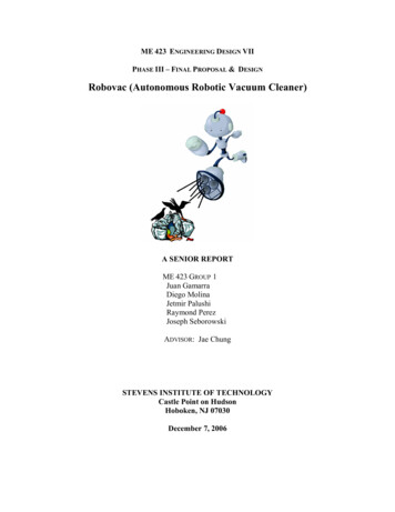
Blowers (pressure drop in system)As stated before, our main objective is to out clean the current market andimproving suction is one way of accomplishing this. Improving suction power within thesystem can be done in many ways. The variables of which will let us know whether ornot our fan achieved great suction are:Power – speed of motor (rpm) plays a big role in how much suction is generatedAirway obstruction – dirty dustbins cause the performance in the vacuum to dropOrifice sizing – the intake ports (suction holes)The diagrams below show how the suction piping will be laid out. There will bethree intake ports for each blower. The blower that will be used the system will provide23 CFM at 12V. The impeller on the blower will spin at the speed of 2300 rpms. Onereason these blowers were chosen was because of their low current consumptions,550mA.The pressure drop in the system was calculated to see whether or not a filterwould be suitable for such a small vacuum. The team discovered that the pressure dropthat was induced by the bends and number of intakes in the system was almost half theinput. The HEPA filters that were originally planned made no sense because they wouldcause too much pressure drop and the goal of cleaning better would not be achieved.The team decided to use large mesh that would capture large objects beforeentering the intake port. This was enough protection to prevent clogging and keep largeobjects from destroying the impeller. The reason that most robotic vacuum cleanersdon’t use a filter is because they don’t have enough power to run a large motor. Anotherreason is that they cannot afford to drain more and more power from the motors as thefilter gets clogged. This means the user has to frequently replace the filter or theperformance of the robot would suffer.It was also decided that we would use a two one stage fans because it would becheaper since a two stage requires two fans and more energy to run. In such a smallsystem the difference was not worth the hassle.GearsGears will be used in the system to send power to the wheels and brushes and willalso help reduce rpms. See attached calculation for power and torque transfer from gearto gear.The main brush will have a spur gear mounted to its shaft and the drive motor willhave another one send power to it through its drive shaft. The material selected for thesespur gears was acetal. The reason for acetal is its high shear strength and also that it canbe purchased off the shelf. Spur gears are suitable for this situation because they areinexpensive and are satisfactory for this simple application. The gears will serve aspower transmitters, but also speed reducers because the motor will be spinning atapproximately 14000 rpms.The brushes throughout the system will received torque and power through bevelgears. The reason for using straight bevel gears in this situation is that they can transmitthe power 90 degrees. The ratio of these gears is one to one which means that all brusheswill be spinning at the same speed. The material is Nylon 6 and this comes from the17
manufacturer in that material. Once again, to save in cost we will be using off the shelfgears.The motor to power the drive wheels will be using helical gears to deliver powerto the crossed drive shafts. The reason we chose helical gears for this application isbecause they have a higher load capacity. The higher load capacity is beneficial becauseall of the weight rest on the torque transfer from these gears. Since they will be movingoften, these gears can also provide a smoother quieter power delivery because they havemore contact. Since this is an off shelf item, it will also be made from Nylon 6.Lastly, the motor that rotates the wheel platform will also use gears. Bevel gearswill be used in the application. The teeth will be crowned so the power can be deliver 90from shaft. The reason for bevel gears is because they are inexpensive and offer the highshear strength of Nylon 6 off the shelf. The gear efficiencies can be seen in Figure 22 ofAppendix.Power Loss Due to FrictionA concern that has been identified is the power loss due to the friction causedbetween the rotating brushes and the floor contact area. Due to the 4 brushes being usedon each side of the robot, there may be some restriction counteracting the movement ofthe drive wheels. The helical arrangement of the bristles will assist in minimizing thisundesired effect.In order to get the most out of the cleaning provided by the spinning of thebrushes, optimally a large amount of friction should be created. However, as previouslystated a trade-off exists between cleaning created by friction and loss of power as a resultof this friction. The correct balance between the two will be determined experimentallybecause too many variables exist to be able to calculate the coefficient of frictionaccurately. Any amount of friction that comes close or matches the load created by thedrive wheels. The flexibility that allows for adjustment when necessary comes with theability to place the brushes extended as desired.CleaningA smaller orifice means more suction force because of the increase in pressurethat can be attained by the system. Increasi
vacuum will either be able to or won’t be able to clean under them. The height of the furniture off the ground is about an inch from the ground or as much as 6 inches from the ground. If the vacuum is able to get under the couch or bed, it probably