Transcription
Dry Floodproofing:Planning and DesignConsiderationsHURRICANE HARVEY IN TEXASPurpose and Intended AudienceThe purpose of this Recovery Advisory is to provideguidance on the design of dry floodproofingmeasures to reduce flood damage and limitinterruption of building services. This advisoryincorporates observations made by the FederalEmergency Management Agency (FEMA) MitigationAssessment Teams (MATs) in Texas and Floridaafter Hurricanes Harvey and Irma. It describes bestdesign practices and successful implementation ofdry floodproofing, as well as lessons learned fromfailures. The information in this advisory is directedtoward existing and new non-residential facilities.This guidance, along with other FEMA publicationsrelated to dry floodproofing, should be usedby building owners and design professionalsexamining ways to reduce future risk. It will alsobe useful to communities and building ownerspreparing designs and proposals for FEMASection 404 Hazard Mitigation grants and hazardmitigation elements included in recovery fundingavailable through FEMA Section 406 PublicAssistance. To improve resiliency in future floodingevents, lessons learned and best practices fromthe MATs can be incorporated into retrofits whendry floodproofing measures are applied to existingbuildings and when designing dry floodproofingsystems for new buildings.The audience for this advisory includes buildingowners, operators, and managers; architects;engineers; building officials; contractors; and localgovernment officials responsible for public buildingplanning, design, and maintenance.Key IssuesThe key issues identified by the MATs during fieldvisits in Texas and Florida are shown in Table 1.A number of these key issues are discussed indetail in other FEMA publications (see the list ofreferences and resources in this advisory) and notDry Floodproofing Planning and Design ConsiderationsRecovery Advisory 1, April 2018Dry FloodproofingDry floodproofing is a combination of measuresthat result in a structure, including its attendantutilities and equipment, being watertight, withall elements substantially impermeable tothe entrance of floodwater and with structuralcomponents having the capacity to resist floodloads (ASCE 24; ASCE 2014).The image below shows an example of dryfloodproofing where a passive opening protectiondeployed to protect a below-grade loading dockwas threatened by rising floodwaters.Photograph courtesy of Andrew Hoyns, Hicks VenturesFEMA Public Assistance Program Funding forDry Floodproofing ProjectsIn addition to funding for repair and recoveryprojects, FEMA Public Assistance (PA) Programfunding may be available for cost-effective hazardmitigation measures that increase resilience, suchas dry floodproofing projects. For more information,refer to Chapter 2 Section VII.C., “HazardMitigation” of FEMA’s Public Assistance Programand Policy Guide (2018).in this advisory. This advisory focuses on key issuesto help fill information gaps or supplement guidance inother FEMA publications.TX-RA1 / April 2018Page 1 of 14
Table 1: Key Issues Identified by MATsKey Topic AreasDiscussed in thisAdvisory?Additional FEMA Sourcesof InformationFEMA P-1019Backup powerYesFEMA P-348 (Chapter 5)Iowa Floods of 2016 RA5Building penetration elevations relativeto base/design flood elevationsYesFlood barrier penetrations andseepage controlYesFEMA P-936 (Sections 2.6.3, 3.4, 3.9, and 3.10)FEMA P-259 (Chapter 5D)FEMA P-312 (Chapters 7 and 8)FEMA P-936 (Section 3.4.3)FEMA 259 (Sections 5D.10 and 5W.12)Issues with sewer system andstormwater systems (ejector pumpswith back-flow preventers)YesRainfall behind the flood barrierYesSeepage disposalYesFEMA P-348 (Section 5.3)FEMA P-936 (Sections 2.2 and 3.7)FEMA P-312 (Section 3.4.2; Chapters 7 and 8)FEMA P-936 (Sections 2.2.8 and 3.7)FEMA P-936 (Sections 2.2.7 and 3.7)FEMA TB 2Use of flood damage-resistantmaterialsYesUse of redundant systems andcompartmentalization/layeredprotectionYesDesign flood elevation requirementsNoHydrostatic forces and buoyancyNoFEMA P-936 (Sections 3.2 and 3.9)See also *FEMA P-348 (Chapter 5)Hurricane Sandy RA5Iowa Floods of 2016 RA1Hurricane Sandy RA2FEMA P-936 (Section 2.2)Hurricane Sandy RA2, RA4, and RA6Performance of critical buildingsystemsNoIowa Floods of 2016 RA3FEMA P-348 (Chapter 5)FEMA P-936 (Section 2.6.3)Note: Complete titles and URLs for each publication are presented at the end of this advisoryRA Recovery Advisory; TB Technical Bulletin*Refer also to Floodproof Commercial Construction: Working for Coastal Communities (Oak Ridge National Laboratory 2011)This Recovery Advisory Addresses"Observations of dry floodproofing system failures"Flood vulnerability assessments"Planning and pre-design considerations"Design considerationsA companion advisory, titled Dry Floodproofing: Operational Considerations (Hurricane Irma in Florida,FL-RA1, 2018) describes deployment considerations (deployment, operations, maintenance, testing) fordry floodproofing.Dry Floodproofing Planning and Design ConsiderationsTX-RA1 / April 2018Page 2 of 14
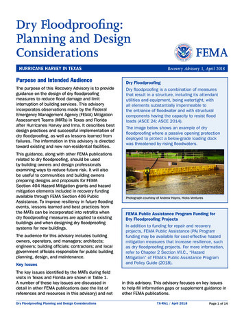
Observations of Dry Floodproofing System FailuresHurricanes Harvey and Irma caused numerous failures in dry floodproofing systems used to protect nonresidential buildings, which led to extensive damage to mechanical, electrical, and plumbing systemcomponents, as well as building and interior finishes, and occasionally structural components. Based on theobservations of FEMA’s MATs deployed after the hurricanes, the performance of dry floodproofing measureswas highly variable, ranging from effective to completely ineffective. Observed failures at dry floodproofedbuildings included overtopping of flood walls or barriers, failure of the opening protections, structural failureof flood barriers, failure to identify lowest point of floodwater entry, seepage issues, and sanitary sewer andstormwater system issues.As a result of these failures, critical building systems located in basements and first floors were damagedand rendered inoperable. Even where opening protection succeeded in holding back most of the floodwater,seepage through the flood barrier and water entry through penetrations resulted in significant damage tointerior finishes and building systems. In addition to failures, there were numerous observations of “nearmisses” where dry floodproofing measures and human intervention prevented widespread flood damage. Ifflood levels had been only slightly higher or if building managers had not taken action before the onset offlooding, many observed successes would have become failures. This section describes the types of failuremodes the MATs observed after Hurricanes Harvey and Irma.Key TerminologyFlood Barrier: The physical barrier, composed ofopening protection, floor slab, and wall system,that separates floodwater from the dry floodproofedportion of the building.Opening Protection: A cover, shield, or door thatcovers a window, doorway, loading dock access, orother opening in a building wall or floor. Sometimescalled “closure device.”Floodwall: A constructed barrier of flood damageresistant materials to keep water away from or outof a specific area. Floodwalls surround a buildingand are typically offset from the exterior walls ofthe building; some floodwalls can be integrated intothe building envelope. Floodwalls are considered acomponent of the overall flood barrier.Flood Entry Point: Any opening, joint, gap, crack,low point, or other location through or over whichfloodwater can enter the dry floodproofed area.OvertoppingFloodwalls and opening protection were overtoppedin locations where the water surface elevation (WSE)exceeded that of the top of the flood barrier.Failure of Opening ProtectionOpening protection failed either because it was notproperly sealed against its frame or because hydrostaticor hydrodynamic forces exceeded the structural capacityof the barrier. Figure 1 shows a submarine door thatfailed at its midpoint due to hydrostatic forces.Structural Failure of Flood BarrierFlood barriers failed in locations where the hydrostaticforces exceeded the capacity of the wall system.Other failures occurred in areas where abandonedbuilding openings were infilled with materials,typically unreinforced masonry, that could not resisthydrostatic forces.Dry Floodproofing Planning and Design ConsiderationsFigure 1: Structural failure of a submarine door fromhydrostatic forces; the door failed along a weld in the doorpanel adjacent to a stiffener (red circle)Photograph courtesy of Carlos Gutierrez, CSF ConsultingTX-RA1 / April 2018Page 3 of 14
Failure to Identify and Protect Lowest Pointof EntryBuildings were flooded when dry floodproofingmeasures were incomplete and did not adequatelyprotect the lowest point of entry from floodwater.Figure 2 shows a building where the low point inthe flood barrier was not identified or protected,allowing floodwater to overtop the low point in theflood barrier.Failure to Maintain Structural Integrity of theFlood BarrierBasements and other below-grade areas wereflooded due to large openings being cut throughthe foundation walls during construction orcapital improvement projects. These openingswere sealed without re-establishing structuralintegrity or impermeability. Sealing these openingswithout making them substantially impermeableand not re-establishing an adequate structuralload path left a weakness in the flood barrier,making it vulnerable to floodwater entry and flooddamage when exposed to hydrostatic forces.Figure 3 shows a 6-foot by 6-foot opening cutinto a foundation wall to provide access for aconstruction project. After construction wascompleted, the opening was filled in with timberframing and gypsum wall board. During HurricaneHarvey, the timber-framed infill wall failed andallowed floodwater to fill the building.Figure 2: Building where floodwater overtopped the unidentifiedand unprotected low point in the flood barrier; overtoppinglocation is obscured by the tree on the left-hand side of theimageSubstantially ImpermeableAccording to the U.S. Army Corps of Engineers(USACE), a wall is considered substantiallyimpermeable if it limits water accumulation to4 inches in a 24-hour period (USACE 1995). Inaddition, sump pumps are required to controlany seepage, and flood damage-resistantmaterials must be used in all areas whereseepage is likely to occur. This standard isthe minimum requirement; it is possible toachieve lower seepage rates, which is stronglyencouraged by FEMA, particularly in newconstruction.Seepage IssuesThe MAT observed several types of seepageissues, described below.Dry Floodproofing Planning and Design ConsiderationsFigure 3: Floodwater entered the building through a large openingcut into a foundation wall; opening is located approximately 12feet above the floorTX-RA1 / April 2018Page 4 of 14
Failure to remove seepage through flood barriers. Numerousbuildings experienced damage to interior finishes as a result ofwater seeping through the flood barrier. Buildings that were notequipped to remove the seepage had several near misses aswater came within inches of critical building systems. In additionto damaging building finishes, water leaking into buildingsrequired basements to be evacuated, caused failures in pumpcontrol panels for sump pumps and potable water supplypumps, and damaged elevator systems. Figure 4 shows anexample of water seepage at a submarine door.Unsealed penetrations through flood barriers. The MATobserved instances of improperly sealed or unsealedpenetrations in flood barriers, such as for utilities, failing andallowing floodwater to enter buildings. Even buildings withextensive and redundant dry floodproofing systems were floodedbecause of penetrations for utilities passing through the floodbarrier not being properly waterproofed and sealed. Figure5 shows an example of unsealed penetrations that allowedfloodwater to enter and flood a subgrade tunnel. Floodwatereventually filled the tunnel to the ceiling, causing 2 inches ofwater to leak into the basement of a connected building.Another significant source of water infiltration was conduits fromutility vaults or electrical pull boxes outside of the flood barrierthat penetrated the flood barrier to interior spaces. Waterfrom inside the vault or pull box was able to flow inside theconduit, often entering the building inside the electrical room orcontrol room.Figure 4: Water seepage at a submarine doorPhotograph courtesy of Facilities and PropertyMaintenance, Harris County Engineering DepartmentFigure 5: Unsealed conduitand utility penetrationsthrough the flood barrier(yellow circles, left) allowedsubgrade tunnel to fill withwater (yellow arrow, right);the penetrations (shownon left image) are on theother side of the door at theend of the tunnel (shownon right image). The utilitypenetrations were sealedafter the flooding, prior to theMAT visit)Photograph on the right courtesyof Facilities and PropertyMaintenance, Harris CountyEngineering DepartmentDry Floodproofing Planning and Design ConsiderationsTX-RA1 / April 2018Page 5 of 14
Failure to waterproof joints in the buildingenvelope. The MAT observed numerous instanceswhere significant water seepage originated fromunsealed joints in the building envelope. Mostwater seepage through unsealed joints occurredwhere the concrete foundation wall stopped,typically 6 inches above surrounding grade, butsignificantly below the base flood elevation (BFE),design flood elevation (DFE), and WSE. Figure 6shows an unsealed joint between the concretefoundation wall and the reinforced masonry wallwith granite facade; if the joint is left unsealed,water can seep into the building. Anothercommon area for water seepage was unsealedjoints between the concrete foundation slab andfoundation wall.Sanitary Sewer or Stormwater System FlowsFailures associated with backflow from sanitarysewers and stormwater conveyance systemsresulted in significant damage to building finishesFigure 6: Unsealed joint (red arrow) between concrete foundationand critical building systems throughout the areaswall and a reinforced masonry wall with granite facing panelaffected by the hurricanes. While most of thebuildings had some type of check valve or backflowpreventer, the system configuration, pressure rating of the piping, age of the piping, and the building functionall contributed to backflow issues. At one location, the issues were the result of occupants remaining inbuildings and using its sanitary systems even after the check valves had been closed as a result of the mainlines becoming surcharged by water pressure generated by floodwater. For buildings that did not have ejectorpumps as part of the sanitary system, sewer water originating from within the building could not overcome thepressure in municipal lines and backflowed into the interior space.Other damage occurred when there were no check valves installed on floor drains connected to stormwaterdrainage networks. When stormwater overwhelmed other components in the drainage network, water wasable to backflow though floor drains and fill dry floodproofed areas from within the building.Flood Vulnerability AssessmentsUnless flood provisions were incorporated into their design,Vulnerability Assessmentsexisting buildings are vulnerable to flooding if they arelocated in or near areas subject to flooding. NumerousAdditional guidance on conducting floodbuildings sustained flood damage as a result of buildingvulnerability assessments is outlined inowners or managers not fully understanding the flood hazardAppendix C of FEMA P-936, Floodproofingfor the building and/or failure to identify and protect allNon-Residential Structures.potential sources of water entry. Flooding can cause damageranging from minor inconvenience to complete closure ofand significant damage to the building. To reduce the likelihood of such damage in future events, buildingowners and managers should consider performing a flood vulnerability assessment to identify equipmentand systems vulnerable to flooding and take actions to reduce their vulnerability to flooding. The informationobtained during the flood vulnerability assessment, combined with building function and staff or tenantcapabilities to deploy dry floodproofing measures, should be used to design the dry floodproofing measures.Prior to performing a flood vulnerability assessment, the floodwater source with corresponding 10-percent-,2-percent-, 1-percent-, and 0.2-percent-annual-chance (10-, 50-, 100-, and 500-year) WSE and the enforcedDFE should be identified for the building. The assessment should determine if the code minimum shouldDry Floodproofing Planning and Design ConsiderationsTX-RA1 / April 2018Page 6 of 14
be applied or whether a higher freeboard is costeffective and should be incorporated into the DFE.Assessments should account for the fact thatonce a floodproofing barrier is overtopped, a dryfloodproofed building is impossible to keep dry andcould negate all floodproofing efforts.Vulnerability assessments should be conductedby a team of architects and engineers workingclosely with building managers, operators, andmaintenance staff. It is highly recommendedthat a surveyor be incorporated into the team toidentify the grades adjacent to the building and theelevations of all pertinent openings and entrancesinto the building, the first floor and subgradefloors, any utility penetrations into the building,and all critical building systems. The vulnerabilityassessment should identify the following:FreeboardFreeboard is a factor if safety, usually feet abovea flood level, used to compensate for unknownfactors that can contribute to flood heights greaterthan calculated heights. Providing freeboard inexcess of code minimums is often a cost-effectivemeans of limiting future damage. FEMA NationalFlood Insurance Program (NFIP) regulations requirea minimum of 1 foot of freeboard. The AmericanSociety of Civil Engineers (ASCE) 24-14, Standardfor Flood Resistant Design and Construction, andHurricane Sandy Recovery Advisory 5 provideadditional guidance and considerations related toflood risk and determining how much freeboard toincorporate into a design."Locations and elevations of building entrances, such as personnel and overhead doors"Locations and elevations of openings, such as windows, vents, and louvers"""""Locations and elevations of utility (electrical, potable water, sanitary sewer, stormwater, chill water, steam,etc.) conduits entering or exiting the buildingLocations and elevations of any unsealed construction joints where water can enterThe components of the sanitary sewer and stormwater systems, i.e., whether there is an ejector pumpsystem or a gravity system, if there is a backflow preventer on the discharge piping, if the system isconnected to backup power, and the location of the pump control panel. Additionally, it would be beneficialto determine the maximum surcharge level in the municipal system.Locations and elevations of the backup power systems, taking note of the building systems connected tobackup power, size and location of fuel tank, and location of exhaust ductworkLocations and elevations of critical building systems, i.e., building electrical components, steam and chillwater, electrical control panels, fire pumps, etc.In addition to determining flood entry points, theteam should consider the effects of water entry.Specifically, if the flood barrier is penetrated, whatareas of the building or building systems wouldbe exposed to floodwater. Clarifying the pathfloodwater will take upon entering the building willidentify optimal locations for installing drains tocollect water seepage or submarine doors to forma redundant barrier. The use of flood damageresistant materials in these areas, and belowthe DFE, will help minimize damage and reducedowntime after the floodwater recedes.Figure 7 is an illustration of an existing buildingwith examples of the types of openings andpenetrations that should be identified during a floodvulnerability assessment.Dry Floodproofing Planning and Design ConsiderationsNational Flood Barrier Testing and CertificationProgramThis program, a partnership among the Associationof State Floodplain Managers, U.S. Army Corpsof Engineers, and FM Approvals, currently testsand certifies four types of products to meetANSI/FM 2510: temporary (perimeter) barriers,closure devices (opening protection), backwatervalves, and mitigation (flood abatement) pumps.Testing and certification standards are currentlybeing developed for semi-permanent barriers andsealants. A list of certified products can be foundat www.nationalfloodbarrier.org.TX-RA1 / April 2018Page 7 of 14
ast-in-place concretefoundation wall and slabComponent123456Building entranceWindowsAccess ramp to loading dockElectric service equipment roomBuilding central plant equipment roomConstruction joint789101112Water serviceSewer lineUtility powerVentilation grillSump pit with sump pumpStormwater drain131415161718Waste lineFloor drainAccess tunnel to adjacent buildingSubmarine doorBackup generator with fuel tankFuel lineFigure 7: Example of an existing building with multiple openings and penetrations below the BFE and DFE; blue numbered circlesindicate a small sample of the types of openings and penetrations that should be identified during a flood vulnerability assessmentand protected by the flood barrierPlanning and Pre-Design ConsiderationsAfter the flood vulnerability assessment and prior to design, each identified opening should be evaluatedto determine the appropriate method of opening protection. Opening protection systems should come froma reputable manufacturer and be compliant with a testing standard such as ANSI/FM 2510 that includes,among other requirements, performance standards for hydrostatic test strength, impact and wear resistance,system leakage (seepage), environmental corrosion, abrasion resistance, and tear and puncture resistance.If the system is not tested in accordance with ANSI/FM 2510, opening protection systems should, at aminimum, have a demonstrated ability to resist hydrostatic forces associated with the DFE. Homemadebarriers should not be used. After the components of the flood barrier have been installed, it is highlyrecommended that they be tested to ensure water tightness.Key considerations. The pre-design process for flood protection systems should be comprehensive, ensuringthat all opening protection components for the entire building can be installed based on the implementationtimeframe used in the building’s emergency operations plan (for more information, refer to the companionFL-RA1, Dry Floodproofing: Operational Considerations). Key considerations should include, but not necessarilybe limited to:"The timing and rate of anticipated floodwater rise, availability of staff and equipment to install the openingprotection, building occupancy classification, daily use of the openings, and maintenance requirements.Dry Floodproofing Planning and Design ConsiderationsTX-RA1 / April 2018Page 8 of 14
""The amount of traffic, whether vehicular or pedestrian. Traffic may affect the selection of openingprotection systems, since gaskets on shields or doors may need to be protected against damage duringday-to-day use.The type of gasket—inflatable or compression—should be considered when selecting opening protectionsystems. Inflatable gaskets tend to be composed of thinner material and are generally more susceptibleto cracking under prolonged exposure to weather and sunlight.Active versus passive protection. The rate of floodwater riseand anticipated amount of advance warning are often the mostimportant considerations in determining whether to use active(requiring human intervention) or passive (automatic) openingprotection (see text box).Openings at elevations that can flood during frequent flood events(e.g., 10-percent-annual-chance [10-year] flood events or strongdownpour) may require passive opening protection (see Figure 8).Another important consideration is the presence of 24/7 on-sitesupport staff—owners of buildings without continuous supportstaff should also consider passive opening protection since theremay not be enough time for a contractor crew to arrive and installactive opening protection systems. On the other hand, passiveopening protection measures require regular maintenance, as theircomponents are exposed to the elements.If active protection is selected, designers need to determine ifthe opening protection will be permanently attached (using hingesor rails) or detached (such as bolted-on shields or flood logs). Itis recommended that brackets or stanchions for active openingprotection systems be incorporated into the design of the exteriorof the building to reduce installation time. The lack of availability ofequipment or staff to move flood protection measures into placein a timely manner can render the flood protection ineffective andleave the building vulnerable.Figure 8: Exampleof passive openingprotection installed toprotect openings in thefloodwall constructedaround an existingbuilding to establisha flood barrier withminimal openingsbelow the DFEActive and Passive OpeningProtectionActive: A dry floodproofing openingprotection system that requireshuman intervention to install thephysical barrier. These systemsare effective only if there is enoughwarning time to mobilize the laborand equipment necessary toimplement them and then safelyevacuate.Passive: A dry floodproofingopening protection systemthat does not require humanintervention to deploy the physicalbarrier.Automatic/Passive BarrierFloodwatersideDry floodprooFloodwatefed sider sideAutomatic/passive barrierDry floodproofed sideNote: Figure mirrored for clarityDry Floodproofing Planning and Design ConsiderationsTX-RA1 / April 2018Page 9 of 14
Design ConsiderationsA successful dry floodproofing systems designshould start with a flood vulnerability assessmentand should consider building use, maintenanceconsiderations, and operational requirementsbefore, during, and after an event (refer to previoussections of this advisory). The design shouldtake a comprehensive approach that addressesall possible points of water entry and allows thebuilding to maintain flood protection effectivenessfor the life of the building.Dry Floodproofing New FacilitiesInstalling dry floodproofing in new constructioninvolves considerations and techniques thatare similar to those used when installing dryfloodproofing in existing buildings. However, withnew construction the floors and wall systemscan be designed and constructed to resist thehydrostatic and buoyant forces without costlyretrofits.Dry floodproofing design is discussed in detail inFEMA P-936, Floodproofing Non-Residential Structures (2013), and Section 6 of the American Society of CivilEngineers (ASCE) 24, Standard for Flood Resistant Design and Construction (2014). Design considerationsare discussed in Chapter 2 of FEMA P-936. Specific dry floodproofing details are addressed in Chapter 3; theintroduction of Chapter 3 provides readers with a list of building retrofitting recommendations.NFIP Floodproofing Certificate. The requirements of the NFIP Floodproofing Certificate are described inFEMA P-936 and should be understood before starting design. The NFIP Floodproofing Certificate requirescompliance with ASCE 24 and is both a design and construction certification. Professional engineers andarchitects should read the Floodproofing Certificate in its entirety and the applicable sections of ASCE 24,FEMA P-936, and Technical Bulletin 3, Non-Residential Floodproofing (FEMA 1993), prior to signing it.Improving reliability of floodproofing measures. Based on the performance of dry floodproofing retrofitmitigation measures observed by the MATs after Hurricanes Harvey and Irma in Texas and Florida, additionalattention must be paid to specific items to improve the reliability of floodproofing measures. The MATsrecommend that the measures described in Table 2 be considered to help avoid the types of system failuresobserved.Combining Flood Risk Reduction MeasuresFor new buildings, the design height of dryfloodproofing can be reduced by using fillmaterial to raise the building site. The image onthe right shows where the designer elevated thebuilding on fill, thereby reducing the height of thedry floodproofing system for the building.Reducing the height of dry floodproofingmeasures allows more flexibility in the design,reduces flood loads, reduces the potential forleakage, and can minimize any loss of function.The image on the right shows a dry floodproofedbuilding that was constructed on approximately3 feet of fill. The building incorporated 1.5 feetof freeboard into floodproofing design, and theflood level during Hurricane Harvey used up 1.0of the 1.5 feet.Photograph courtesy of Kati SouthernDry Floodproofing Planning and Design ConsiderationsTX-RA1 / April 2018Page 10 of 14
Table 2. Dry Floodproofing Design ConsiderationsItemDescriptionBackflow preventersInstall backflow prevention valves for any piping in the building below the floodprotection elevation or that connects to other piping networks that extend below theflood protection elevation. Backflow prevention systems can be either passive oractive.Building systemlocationsLocate building systems (e.g., mechanical, electrical, and plumbing components;communication systems; potable water supply pumps; fire suppression equipment)above the DFE. Consider relocating critical building systems above the floodprotection elevation. If relocating is not possible, consider installing redundantprotection systems and protecting these systems to a higher-severity flood eventthan the rest of the dry floodproofed area.Design forcesFlood load calculations should address both lateral hydrostatic and verticalbuoyancy forces, as well as velocity, debris impact, and wave forces, if applicable.Wall and floor systems may need to b
Failure to Maintain Structural Integrity of the Flood Barrier Basements and other below-grade areas were flooded due to large openings being cut through the foundation walls during construction or capital improvement projects. These openings were sealed without re-establishing structural