Transcription
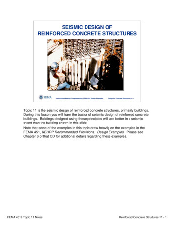
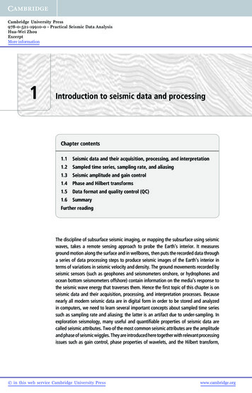
International Journal of Scientific & Engineering Research Volume 3, Issue 6, June-2012ISSN 2229-55181Seismic Evaluation of Existing ReinforcedConcrete BuildingDinesh J.Sabu 1, Dr. P.S. Pajgade 2ABSTRACT: The recent earthquakes have exposed the vulnerability of the existing reinforced concrete buildings in India. The Bhuj earthq uake (2001)saw a great deal of damage to multi-storey buildings in the urban area of Gujarat. This has posed a serious threat to the many existing Indian RCbuildings which are designed mainly for gravity loads. The need for evaluating the seismic adequacy of the existing structures has come into focusfollowing the damage and collapse of numerous concrete structures during recent earthquakes. In order to carry out seismic evaluation, a simplifiedprocedure for evaluation is highly in need for a country like India which is prone to earthquakes. It is important to estimate the response of buildingsunder earthquakes from the viewpoint of life reservation and risk management. The Response Spectrum analysis procedure is app lied for the evaluationof existing design of a reinforced concrete bare frame, frame with infill and frame with infill and soil effect. In order to examine the performance of thesemodels, the Response Spectrum analysis for seismic evaluation of existing buildings is performed. After performing the analys is reinforcement requiredin each format is determined and retrofitting is suggested accordingly. Different retrofitting method are studied in this wor k. Also it is concluded that theeffect of infill plays very crucial role in seismic evaluation of existing RC buildings.Keywords— Masonary infill wall, equivalent diagonal strut, reinforced concrete, retrofitting,—————————— ——————————1. INTRODUCTIONAmongst the natural hazards, earthquakesDuring the last century, 4 great earthquakes struck differenthave the potential for causing the greatest damages toparts of the country: (1) Great Assam earthquake (1897), (2)engineered structures. Since earthquake forces are randomKangra earthquake (1905), (3) Bihar Nepal earthquakein nature & unpredictable, the engineering tools needs to be(1934) and (4) Assam earthquake (1950). In recent times,sharpened for analyzing structures under the action ofdamaging earthquakes experienced in our country includethese forces. India has a number of the world’s greatest(1)earthquakes in the last century. In fact, more than fiftyearthquake (1991), (3) Killari earthquake (1993), (4) Jabalpurpercent area in the country is considered prone toearthquake (1997), (5) Chamoli earthquake (1999) and (6)damaging earthquakes. The northeastern region of theBhuj earthquake (2001) and recently occurred (7) Westcountry as well as the entire Himalayan belt is susceptibleBengal earthquake (2011). In all of these earthquakes thereto great earthquakes of magnitudeis huge loss of life and very large destruction of existingmore than 8),buildings.(2)UttarkashiMostrecentconstructions in the urban areas consist of poorly designedand constructed buildings. The older buildings, even ifconstructed in compliance with prevailing standards, maynot comply with the more stringent specifications of thelatest standards of IS 1893( Part 1):2002, IS 4326:1993 and IS13920: 1993. The existing buildings can become seismicallydeficient since design code requirements are constantlyupgraded due to advancement in engineering knowledge.Investigations of past and recent earthquakedamage have illustrated that the building structures areFig 1: Area expose to seismic risk in Indian Classification12Final Year Student (M.E. Structure) , ProfessorDepartment Of Civil EngineeringProf. Ram Meghe Institute of Technology & ResearchBadnera, Amravati-444701, Maharashtra, IndiaEmail ID: saboodj@yahoo.comEmail ID: ppajgade@gmail.comvulnerable to severe damage and/or collapse duringmoderate to strong ground motion. An earthquake with amoderate magnitude is capable of causing severe damagesof engineered buildings, bridges, industrial and portfacilities as well as giving rise to great economic losses.IJSER 2012http://www.ijser.org
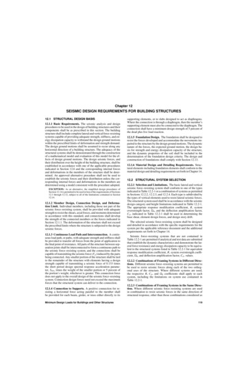
International Journal of Scientific & Engineering Research Volume 3, Issue 6, June-2012ISSN 2229-55182After the Bhuj earthquake (2001) considerable interest inThe vulnerability of the structure can be assessedthis country has been directed towards the damaging effectwith a higher accuracy and better informed decisions canof earthquakes and has increased the awareness of thebe made on the possible improvement of the seismicthreat of seismic events. Most of the mega cities in India areresistance of existing RC structures. For example, thein seismically active zones and are designed for gravitycritical components of the structure that are likely to sustainloads only. The magnitudes of the design seismic forcessignificant damages during future earthquake groundhave been considerably enhanced in general, and themotions may be identified. Accordingly, the requiredseismic zonation of some regions has also been upgraded.immediate structural interventions may be designed toThus a large number of existing buildings in India needsreduce the deformation demands on these components.seismic evaluation due to various above mentionedSubsequently, the overall behavior of the structure may bereasons. Hence evaluation of existing RC buildings in Indiaimproved to achieve a satisfactory overallis a growing concern.performance during a future earthquake.2. METHODS OFRETROFITTING1.2 NEED FOR SEISMIC EVALUATIONSEISMICANALYSISseismicAND2.1 METHODS OF ANALYSISIt is known that damaging earthquakes are veryoften followed by a series of aftershocks and sometimes byFor seismic performance evaluation, a structural analysis ofother main shocks. Past earthquakes have shown that whenthe mathematical model of the structure is required tourban areas are hit by damaging earthquakes, a significantdetermine force and displacement demands in variouspercentage of structures attain light to moderate damage.components of the structure. Several analysis methods,Moreover, it is known that structures that sustained someboth elastic and inelastic, are available to predict thedamages prior to seismic event may collapse during aseismic performance of the structures. Following are somesucceeding event. Such unfortunate events have claimedof the seismic analysis methods used for seismic evaluation;1.many lives. Therefore, these structures impose a potentialElastic methods of analysisrisk to human life, economic assets and the environment.A. Linear static analysisThus, making decisions regarding the post-earthquakeB.2.functionality and repair of the damaged structures is aLinear dynamic analysisInelastic methods of analysiscritical part of the post-earthquake recovery process. Also,A. Nonlinear static analysisfrom the effects of significant earthquakes that has struckB.Nonlinear dynamic analysis.the different parts of country, it is concluded that theseismic risks in urban areas are increasing and are far fromsocio-economically acceptable levels. Therefore there is anurgent need to reverse this situation and it is believed thatone of the most effective ways of doing this is through:(1) The seismic evaluation of existing stuck offstructures.(2) The development of more reliable seismicstandards and codal provisions than those currently2.1. Single equivalent diagonal strut modelsIn this method the analysis is carried out by simulating theaction of infills similar to that of diagonal struts bracing theframe. The infills are replaced by an equivalent strut oflength D, and width W, and the analysis of the frame-strutsystem is carried out using usual frame analysis methods.The relationships proposed by Mainstone Walls have toresist the shear forces that try to push the walls over.available with their stringent implementation for thefor computing the width of the equivalent diagonal strut, iscomplete engineering of new engineering facilities.widely used in the literature and is given by.Therefore,anaccurateestimationoftheperformance of structure during an earthquake is crucialfor estimating the actual effects of that earthquake on theexisting RC structures.IJSER 2012http://www.ijser.orgW 0.175 (λ H)-0.4 D
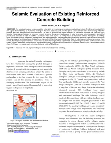
International Journal of Scientific & Engineering Research Volume 3, Issue 6, June-2012ISSN 2229-55183buildings, this process typically includes strengtheningweak connections found in roof to wall connections,continuity ties, shear walls and the roof diaphragm. In thepast, building codes were less stringent compared totoday’s standards, thus it is a good idea to inspect buildingsconstructed prior to 1998, as they were built prior to currentstructural codes/requirements (1997 UBC).It is the method of strengthening of the already builtdamaged/ undamaged old/new structures those are foundto be weak in earthquake loadings that may occur in future.Generally, structuresvulnerabletoearthquakes areretrofitted by means of steel jacketing, Concrete jacketing,Fig 2.1 shows equivalent diagonal strut modelGaivanized steel mesh reinforcement, inclusion of newsupporting walls/ concrete shear walls, Steel bracings, FiberReinforced polymer (FRP) Sheets or by any other suitablemeans.whereRetrofitting works may also be necessary in a well builtbuilding if extra storeys are to be added .Also old-weakλ Stiffness reduction factorbuildings can be extended after properly strengthening theEi the modules of elasticity of the infill material, N/mm2older part so as to bear the increased safety demand due tothe extended part.Ef the modules of elasticity of the frame material, N/mm2Selection of the Proper Retrofitting MeasureIc the moment of inertia of column, mm4t the thickness of infill, mmProper study of the existing structure usingvarious analytical tools need to be carried out to identifyH the centre line height of framesthe weak zones within the structure prior to carrying outh the height of infillretrofitting works. It also helps in the selection of properL the centre line width of framesretrofitting measure that should be adopted in terms ofeconomic and safety aspects.l the width of infillBuilding structures lying in acceleration sensitiveD the diagonal length of infill panelregion and velocity sensitive region of the spectrum mayθ the slope of infill diagonal to the horizontal.require different retrofitting measures. Retrofitting optionsuitable for one structure may prove to be inefficient forWidth of strut without opening (W)another structure with different dynamic behavior.W 0.175 (λ H)-0.4 DAlso, after retrofitting, stiffness of a buildingPutting the value of stiffness reduction factor in aboveequation, width of strut has been calculated for estimationof width of strut without opening,structure may increased significantly, thereby increasing aload demand on the structure than before retrofitting.Increase in stiffness also depends on the type of theretrofitting measure carried out.2.2 RETROFITTINGAlso, after retrofitting stiffness of a buildingWhat is Seismic Retrofitting?A Seismic Retrofit provides existing structures with morestructure may increase significantly, thereby increasing aresistance to seismic activity due to earthquakes. Inload demand on the structure than before retrofitting.IJSER 2012http://www.ijser.org
International Journal of Scientific & Engineering Research Volume 3, Issue 6, June-2012ISSN 2229-55184Increase in stiffness also depends on the type of theimprove shear. Bending, Axial & Ductile capacity ofretrofitting measure carried out. Conventional retrofittingstructural members & the structure as a whole. Most of themeasures as steel/ concrete Jacketing and inclusion of newexisting practices seem to provide increased confinement ofwalls are likely to increase the stiffness of the structurethe structural members-mainly increasing axial, Shear andsignificantly. Thereby, altering its dynamic behavior inductile behavior. Increase in bending capacity could also besuch re-analysis of the retrofitted structure shall be carriedachieved if proper detailing and design principle isout Modern jacketing technique such as Fiber Reinforcedfollowed.Polymer(FRP) wrapping could be the best way tostrengthen the capacity of structures without alteringstiffness.Concrete jacketing involves addition of a layer of concrete,Besides the increment in stiffness of the structure,majorrepercussion in the conventional2.2.1 Concrete Jacketingmethod ofretrofitting could be the development of new load pathsthat may lead to concentration of loads at the foundationlevel. This happens in reinforced concrete (RC) framestructures, where inclusion of concrete shear walls inbetween the columns is carried out as a retrofittingmeasure. In such, existing foundation of the adjoiningcolumns is likely to get overstressed.longitudinal bars and closely spaced ties. The jacketincreases both the flexural strength and shear strength ofthe column. Increase in ductility has been observed(Rodriguez and Park,1994). If the thickness of the jacket issmall there is no appreciable increase in stiffness. Circularjackets of ferro-cement have been found to be effective inenhancing the ductility. The disadvantage of concretejacketing is the increase in the size of the column. Theplacement of ties at the beam column joints is difficult, ifnot impossible. Drilling holes in the existing beamsSelection of the proper retrofitting technique shalldamages the concrete, especially if the concrete is of poorbe done by carrying out the detail analysis of the existingquality. Although there are disadvantages, the use ofstructure. Re-Analysis including Re-Design of the structureconcrete jacket is relatively cheap. It is important to notemay be required after the introduction of retrofittingthat with the increase in flexural capacity, the shearmeasures. So that the objective of Seismic Retrofitting isdemand (based on flexural capacity) also increases. Themet.additional ties are providing to meet the shear demand.There can be several schemes of providing aRetrofitting Design Principlesconcrete jacket. A scheme is selected based on theDesign principles, even in case of retrofitting as in case ofnew construction shall follow several factors.dimensions and required increase in the strength of theexisting column, available space of placing the longitudinalFor instance in order to have a full advantage ofthe potential ductility of retrofitted RC members. It isdesirable to ensure that flexure rather than shear governultimate strength. Shear failure is catastrophic and occurswith no advance warning of distress. Many of existing RCcolumns and Beams have been found deficient in shearstrength and in need of strengthening.bars. To increase the flexural strength, the additionallongitudinal bars need to be anchored to the foundationand should be continuous through the floor slab. Usuallythe required bars are placed at the corners so as to avoidintercepting the beams which are framing in to the column.In addition, longitudinal bars may be placed along the sidesof the column which are not continuous through the floor.These bars provide lateral restraint to the new ties. A fieShear Deficiencies occur due to several reasonscannot be made of a single bar due to the obstruction insuch as insufficient shear reinforcement or reduction inplacement. It can be constructed of two bars properlysteel area due to corrosion, increased service load, designanchored to the new longitudinal bars. It is preferred toprinciples in older codes and construction defects. As far ashave 135 hooks with adequate extension at the ends of thepossible design principle in case of retrofitting shall be tobars.IJSER 2012http://www.ijser.org
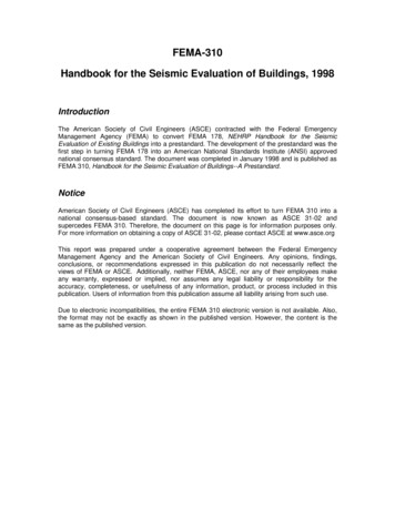
International Journal of Scientific & Engineering Research Volume 3, Issue 6, June-2012ISSN ons fortheconcretejacket areas follows(DraftCode)a) The strengths of the new materials must be equal to or greaterthan those of the existing column. The compressive strength ofconcrete in the jacket should be at least 5MPa greater than that ofthe existing concrete.b) For columns where extra longitudinal bars are not requiredfor additional flexural capacity, a minimum of 12mm, diameterbars in the four corners and ties of 8 mm diameter should beprovided.c) The minimum thickness of the jacket should be 100 mm.d) The minimum diameter of the ties should be 8 mm andshould not be less than ? of the diameter of the longitudinal bars.The angle of bent of the end of the ties should be 135.e)The centre-to-centre spacing of the ties should not exceed200mm. preferably, the spacing should not exceed the thicknessof the jacket. Close to the beam-column joints, for a height of ¼the clear height of the column. The spacing should not exceed100mm.35Brick masonry Infill Details1] strength of brick4 N/mm2masonry2] unit weight of20 kN/m3masonry3] modulus of elasticity2035 N/mm2of brick masonry(550fm)4] Thickness of230mmperipheral wall5] Poisson’s ratio0.156] Single strut modelwidtha) along X-directionb) along Y-directionSoil PropertiesTypeE (Modulus ofElasticity)Poisson’s mGravel120 N/mm20.15ANALYSIS PROBLEM3.1 STRUCTURAL DETAILS:RC Frame Details1] Grade of concrete2] Grade of steel3] modulus of elasticityof concrete4] modulus of elasticityof steel5] unit weight ofconcrete6] Poisson’s ratio7] Sizes of beams8] Sizes of columns20 N/mm2415 N/mm222.36 kN/m2Fig 3.1:view of building.2x105 kN/m225 kN/m30.2230x300mm,230x380mm,230 x 450mm230x300mm,230x380mm,230 x 450mmIJSER 2012http://www.ijser.org
International Journal of Scientific & Engineering Research Volume 3, Issue 6, June-2012ISSN 2229-55183.2 Analytical ModelsFor the analysis and design purpose four model has beenconsidered namely as1. Bare frame (S.M.R.F infill frame with masonary effect notconsidered)2.Fully infilled frame (S.M.R.F infill frame with masonaryeffect considered)6in brick infill or soil interaction model effect than there isneed of retrofitting to the particular member. The mainparameter are to be considered in the study arereinforcement of members and maximum displacement ofthe building.Table:- 4.1. Reinforcement Comparison of building.3. Infilled frame with centre opening (15%)4. Infilled frame with corner opening (15%)Ast Required(mm2)SizeAst(mm xPro.mm)(mm2)Bare FrameInfill WallSoil EffectYes/NoG.F C1230 x 300678847783730NOF.F.C1230 x 300678374530530NOS.F.C1230 x 300678121616616NOT.F.C1230 x 300678412674673NOG.F C2230 x 380904No Design903869NOF.F.C2230 x 380904No Design704704NOColumnIDRetrofittingRequiredFig 3.2: bare frame modelS.F.C2230 x 380904No Design477477NOT.F.C2230 x 380904No Design182182NOG.F C3230 x 230 x 300678No DesignNo DesignS.F.C3230 x 300678No DesignNo DesignT.F.C3230 x 300678No DesignNo DesignG.F C5230 x 300678No Design678660NObeen selected for getting results and they are as columnF.F.C5230 x 300678No Design670670NOno.C1,C2,C3 & C5. The results found to be are shown withS.F.C5230 x 300678679440440NOthe help of graph for the parameter.T.F.C5230 x 300678453179179NOFig 3.3: Fulley infilled frame modelYesYesYesThe above mentioned all frame has been designed by usingSTAAD-Pro software.For getting results some column has1. Ast4. COMPARISON OF RESULTSData of reinforcement provided to the actualbuilding is obtained, and compared with the reinforcementrequired in brick infill effect model and brick infill soilinteraction effect model under seismic design. From thecompression if actual reinforcement is more than thereinforcement required in the brick infill and soilinteraction effect than there is no need to retrofit the actualsection, it is sufficient to carry the seismic forces. But ifactual reinforcement is less than the reinforcement requiredIJSER 2012http://www.ijser.org
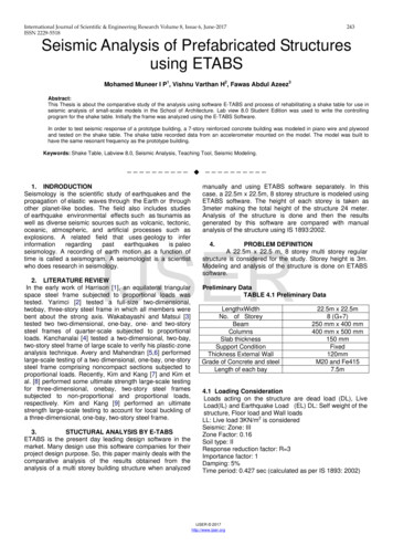
International Journal of Scientific & Engineering Research Volume 3, Issue 6, June-2012ISSN 2229-55187Figure No.4.2.: Column JacketingTable:- 4.2. Reinforcement Comparison of building AfterRetrofitting.Figure No.4.1.:- Displacement comparison of buildingElementIDSize(mm xmm)AstProvided(mm2)G.F.C3450 x 380F.F.C3From the above figure it is found that in Brick infill soilAst Required (mm2)BareFrameInfillWallSoilEffect904 4521041930870450 x 380904 452886861861S.F.C3450 x 380904 452545345345T.F.C3450 x 380904 452779223223interaction effect frame model deflection reduced by 90 92% as compared to bare frame model.Retrofitting:In case study building no 1 column C3 needsretrofitting. So for retrofitting, concrete jacketing method isrecommended which involves additional layer of concreteof about 75 mm from all the sides, longitudinal bars andCONCLUSIONS:-closely spaced ties.After the retrofitting the analysis and design isThe whole study is concentrated on seismic evaluation anddone again and required reinforcement is calculated. Belowretrofitting of existing RC building. Seismic analysis istablecarried out for existing reinforced concrete building. thereinforcement provided in building is compared with allthe three formats of modeling i. e. Bare frame modeling,brick infill frame modeling, and infill soil effectinteraction model. After all the study the followingconclusions are drawn . It is concluded that if the strengthening is done assuggested in this thesis, the strength of the existingstructure can be enhance to the required level andit will definitely improve the seismic resistancecapacity of the building required for zone III. It is concluded that concrete jacketing method iseasy,IJSER hodfor
International Journal of Scientific & Engineering Research Volume 3, Issue 6, June-2012ISSN 2229-5518improving the seismic resistance capacity of the plastic hinge properties in nonlinear analysis ofResults indicate that infill panels have a largereinforcedthebehaviorearthquake excitation.offrames7) Yogendra Singh Dipankar Das, ‘Effect Of URMFrom the result it is observed that due to infillBuildings, 4 International Conference on Earthquakeeffect stiffness of the frame increases and due toEngineering Taipei, Taiwan, October 12-13, 2006.8)Al-Amin, ‘Study the Reinforced Concrete Frameframe.with Brick Masonry Infill due to Lateral Loads’,Deflection is very large in bare frame compared toInternational Journal of Civil & EnvironmentalEngineering IJCEE-IJENS, 10(4), 2010.It is concluded that about 30% to 40% less9)Siamak Sattar and Abbie B. Liel, ‘Seismicreinforcement required in building with brick infillPerformance of Reinforced Concrete Frame Structures soil interaction effect as compare to bare frame inWith and Without Masonry Infill Walls’, Department.ground storey. And relatively less difference inofreinforcement in other upper storey.Engineering, University of Colorado, Boulder,If methodology (analyzing by considering effect ofEnvironmentalandArchitecturalinfill wall soil effect is adopted for newconstructions then it will be useful in determiningK. Jain, ‘Effectiveness of Some Strengtheningthe economical structural memberOptions for Masonry-Infilled RC Frames withsizes forOpen First Story’, Journal of Structural Engineering,135(8), 925–937, August 1, 2009.G.Asteris,S.T.Antoniou,D.S.Prof. Ravi Sinha and Prof. Alok Goyal, tical Macro-Modeling of Infilled Frames:Assessment of Buildings and Procedure for RapidState-of-the-Art’. Journal of Structural Engineering,Visual Screening of Buildings for Potential SeismicJuly 15, 2009.PolicyforSeismicChrysostomouC.Z,12) K.A.Korkmaz, F. Demir and M. Sivri, ‘EarthquakeIndian Institute of Technology Bombay, 2011.Assessment of R/C Structures with Masonry InfillA.M. Mwafy, A.S. Elnashai, ‘Static pushoverWalls’, International Journal of Science & Technology,versus dynamic collapse analysis of RC buildings’,2(2), 155-164, 2007.Engineering Structures, 23, 407–424, ing Of Buildings and Structures’, ISETJournal of Earthquake Technology, 4, Paper No.469, 31-48, March-June 2006.Kerstin Lang, ‘Seismic vulnerability of existingbuildings’, Ph.D. Thesis, Swiss Federal Institute ofTechnology5)Civil,2010.10) Hemant B. Kaushik Durgesh C. Rai and SudhirVulnerability’, Department of Civil Engineering,4)Performance of RC FrameKashif Mahmud, Md. Rashadul Islam and Md.11) P.3)Seismicthas compared to reinforcement required in bareReference:2)EngineeringInfills onearthquake resistance.1)buildings’,increase stiffness of the structure.in-filled frame. concreteStructures, 28, 1494–1502, 2006.underIn general, infill panelswhich comparatively less reinforcement is required Mehmet Inel and Hayri Baytan Ozmen, ‘Effects ofmember and building as well.effect on 6)8Zurich,UniversityofLondon,England, 2002.Kaliprasanna Sethy, ‘Application Of PushoverAnalysis to RC Bridges’, Ph.D. Thesis, hnology, Rourkela Orissa, 2011.IJSER 2012http://www.ijser.org
percentage of structures attain light to moderate damage. Moreover, it is known that structures that sustained some damages prior to seismic event may collapse during a succeeding event. Such unfortunate events have claimed many lives. Therefore, these structures impose a potential